People tend to design around their particular expertise. A machinist will design based on machining parts out of solid billet, a welder will design for a weldment, and the guy with a foundry will design for castings. The point being, designing is often like driving across town. Very rarely is there only one way to get from point A to point B.
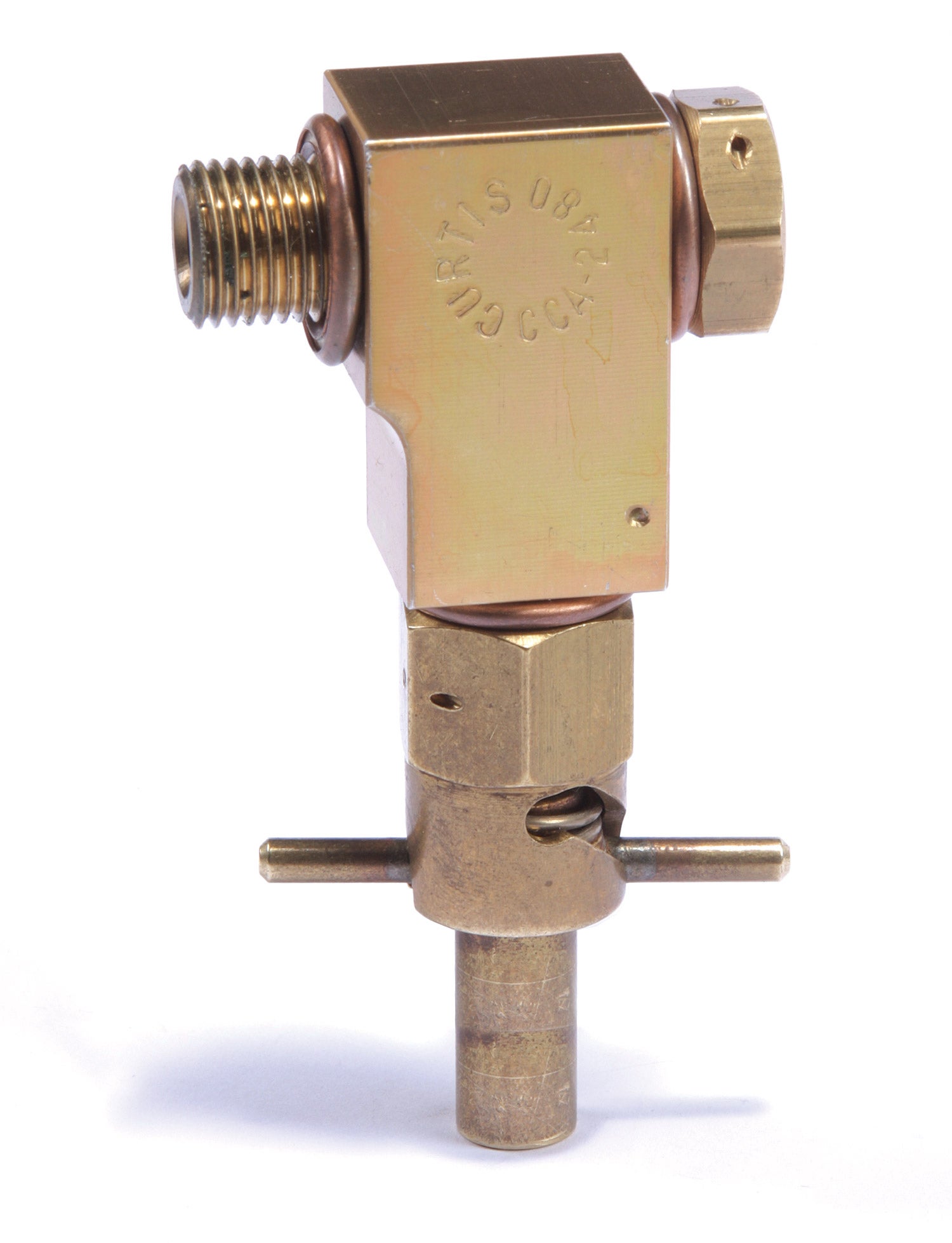
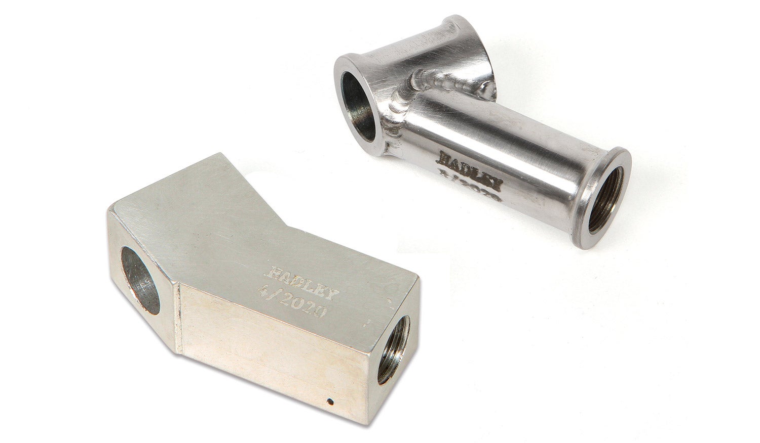
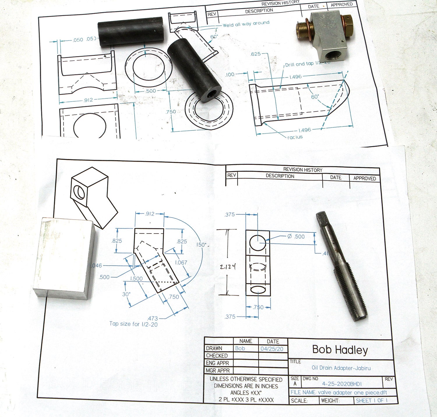
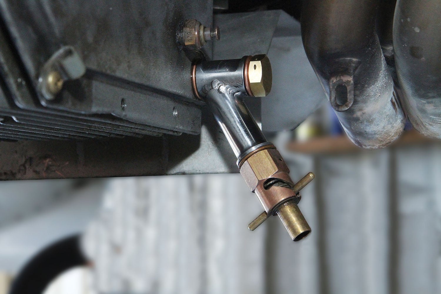
This month’s project illustrates two approaches to the same end: an angled adapter for a Curtis quick-change oil valve for my new Jabiru engine. The standard 90° Curtis adapter for the Jabiru didn’t provide enough clearance for my particular installation. The April 2017 issue of KITPLANES® covered a solution for making an elbow to fit the same drain valve for my original engine. While that worked fine, it required getting my hand pretty close to the exhaust pipe to twist the valve open. The new engine offered the chance to rethink the idea. I decided a version based on the Curtis design, but with a different angle, would make the valve more accessible.
The Curtis elbow adapter is nicely machined from billet aluminum (though I have seen an older, identical elbow made from brass), so the natural choice was to make the new one out of the same material.
But suppose it’s a Friday night and you want to get this made on Saturday so you can be in the air on Sunday. You’ve rummaged through your material supply, including cutoffs and leftovers from other projects. All you have is some 3/4-inch steel bar stock. But you also have a TIG welding machine. Can this part be a weldment? The part is small, so weight is not a factor. It’s not subject to any unusual stress or structural loading of any kind. All things considered, there’s no reason against a weldment as a viable option.
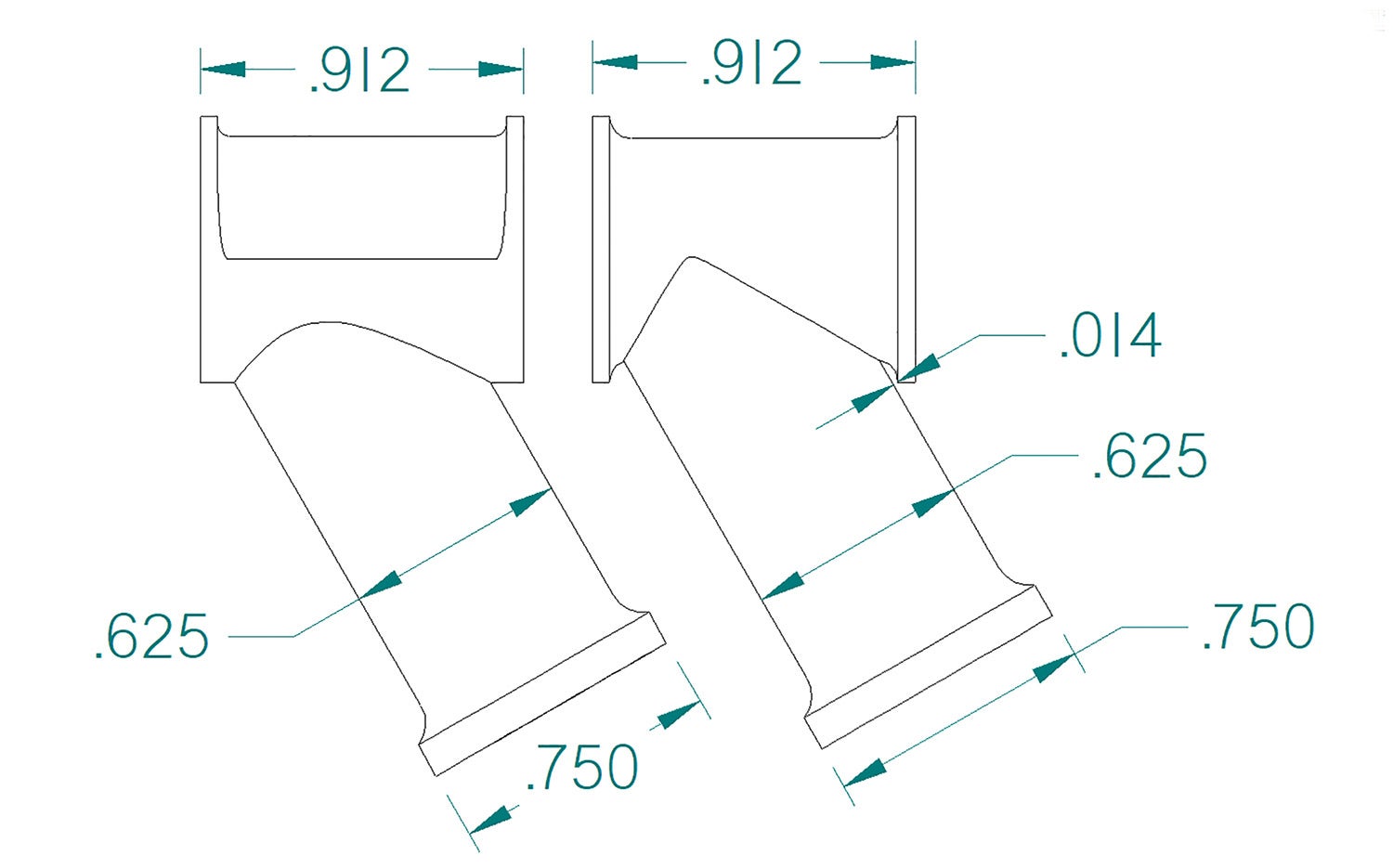
The weldment design still required a bit of machining, mostly to remove excess material (i.e., weight). Note especially how the drain tube (the angled extension) is concentrically turned to 5/8-inch diameter, while leaving a 3/4-inch face flange to insure a proper seat for the MS 35769-9 gasket.
When I made my initial sketch, I had the cross tube slimmed down in a similar manner: a 5/8-inch-diameter center section with ¾-inch flanges at each end for sealing. However, my experience designing parts for welding immediately told me that was not going to work. TIG welding into those tight gaps would burn through and ruin the flanges.
My solution was to eliminate the flanges, but lighten the cross tube using a lathe trick called off-axis turning. While it doesn’t remove as much weight, it makes for a cool-looking part and solves the problem of trying to weld around a flange.
The Off-Axis Experience
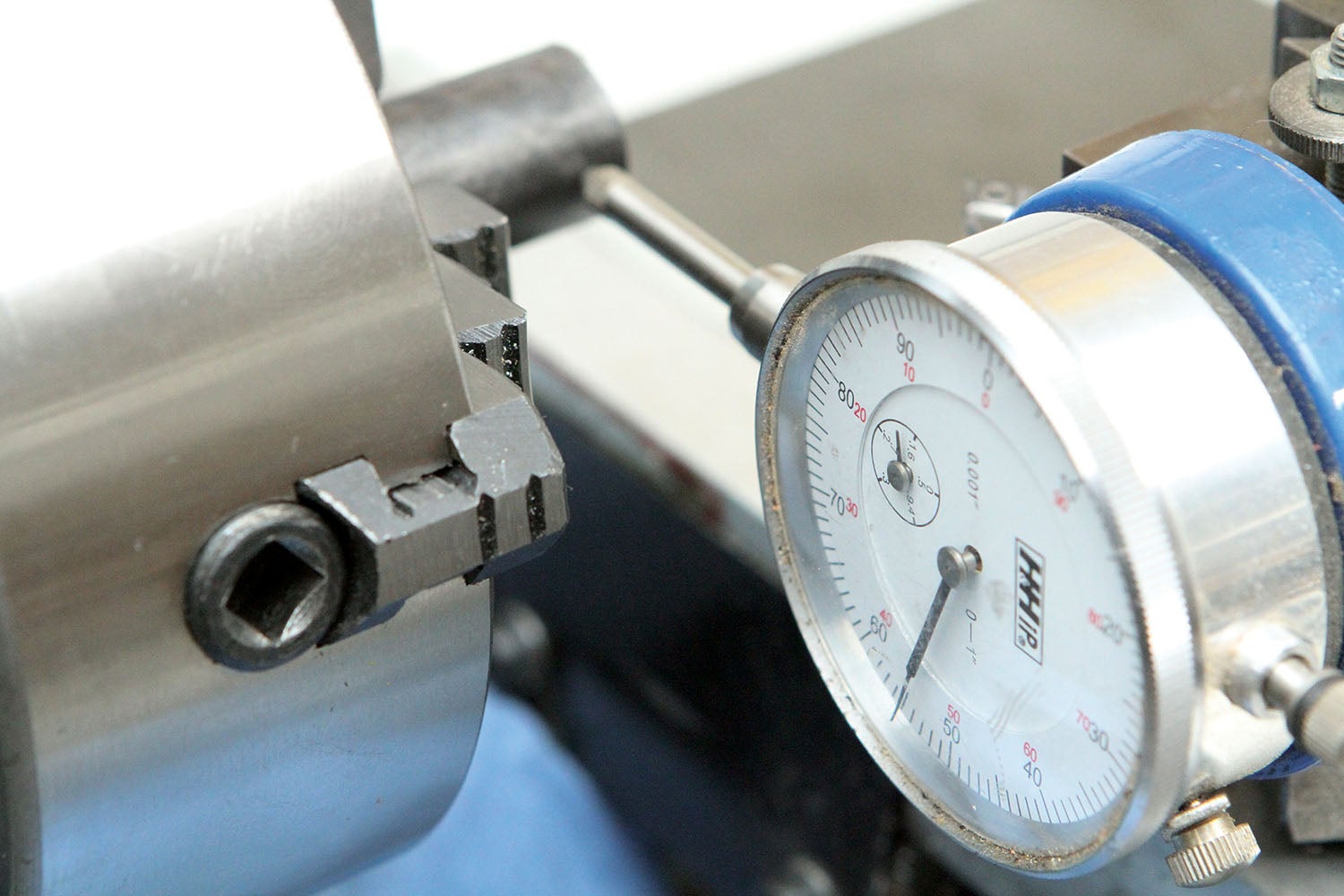
Your first off-axis turning experience will be just that: an experience. The very nature of this type of turning seems unnatural because you are—on purpose—setting up the lathe to be out of balance. How much out of balance depends on the size, weight and how far off-axis you set the part. A small part (like the one shown) in a heavy lathe may not vibrate much, if at all. But the same part in a small bench lathe might shake like a bad California earthquake.
When making an off-axis turning, start with the lathe rpm at its slowest setting and gradually increase the rpm. If the lathe starts to shake before you reach the normal rpm for turning (500 to 800 rpm for a small part like this one), then back off.
The tool will be making an “interrupted cut,” which means, for each rotation of the spindle, the tool will be cutting only the offset side. This tends to freak out some people, but once you get used to it, it’s no big deal. The secret is to ease the tool into the spinning part and take light cuts. If you get too aggressive, you will know it from the sound of the tool slamming into the part. You want more of a “whoosh-whoosh-whoosh” sound of chips coming off the tool than a “bang-bang-bang” sound of the tool crashing into the part.


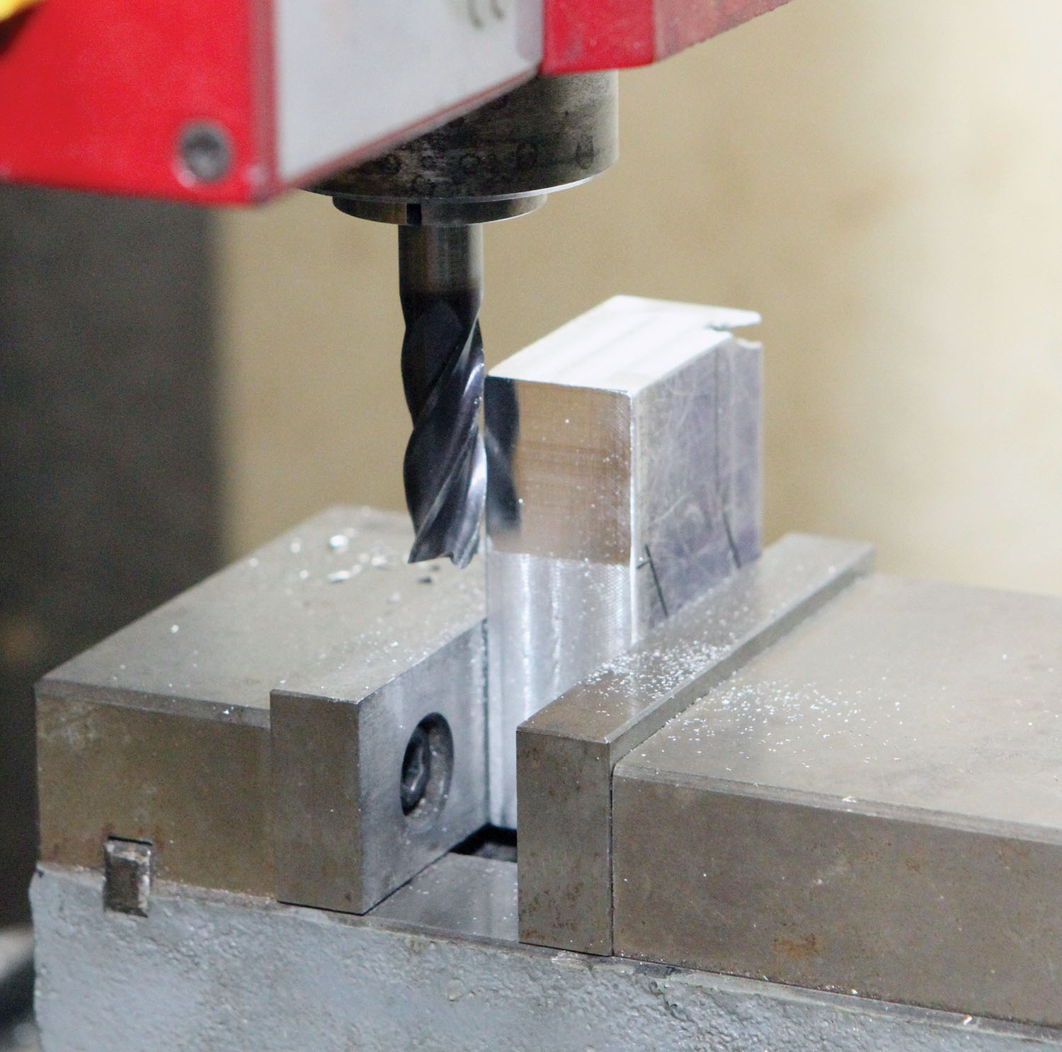


The Billet Adapter
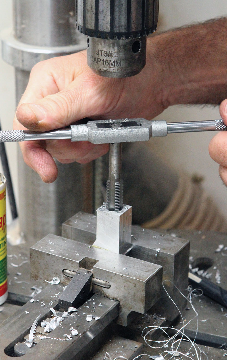
The billet adapter was in fact easier to make, but the faces must be square to the holes to assure they won’t leak. A good machinist square is as important to this project as the milling machine and drill press.
A few closing thoughts on Curtis drain valves. They are, in my opinion, a must-have accessory for anyone who does their own oil changes. You simply push a 3/8-inch rubber hose on to the outlet pipe, stick the other end in your drain pan and twist the valve a quarter turn to open. No oil dribbling out of the pan, no oil on your hands and no oil on the floor! Curtis makes a wide range of valves for almost any application, and while their elbow adapter didn’t work for me, it was an easy job to make one and a good example of the utility of the home shop when it comes to customizing your airplane. That’s it for this month; time to get out in the shop and make some chips!
Download the drawings:


Hi Bob –
Enjoyed your article on the two methods of part fabrication, as it brought back some aspects of my own work as a design engineer. Never particularly gifted with hands on skill sets, my part was to make design drawings for others to build and I found that there were some distinct preferences between machinists and welders when it came to drawings. The machinists generally wanted smaller drawings, such as page size or 11 x 17 at the largest, as they generally had few places to put drawings around the machine tools. Welders, on the other had, tended to prefer larger C or D size drawings that they could spread out on their welding tables and read from a distance. Similarly, if you found a drawing on the shop floor, face down, you could usually guess who might have lost it, as the machinists drawings were usually oil smudged and the welders drawings would have holes burned in them. Go figure.
Comments are closed.