 Inspection panels are required for both assembly and maintenance of various aircraft systems. Most kit aircraft will have the location of the panels specified in the plans and may have the holes already cut out or molded into the part. For folks who wish to fabricate custom panels, this article shows how to make your own. The method here is intended for composite aircraft, but for the odd wood-skinned plane this might make sense too.
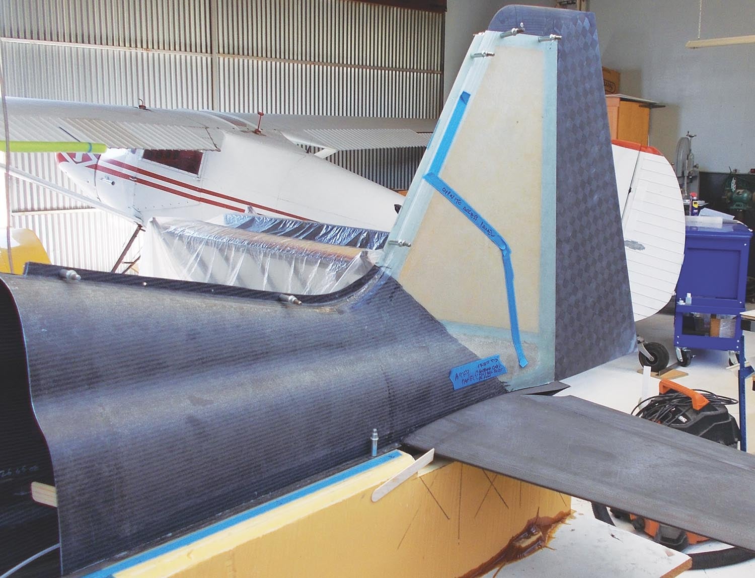
First off, let me point out that the easy way to do this is to make the access panel before making the skin it fastens into. The panel itself is fabricated by laying up fabric in the mold where the panel goes—the mold should have scribe lines indicating the outline of the panel. This small layup is removed once cured and the panel trimmed to final shape as shown by the scribe lines. It is then released (i.e., waxed or sprayed with a release agent) and put back into the mold, being held firmly in place with contact cement. You can see this method in action during the fabrication of this sailplane wing skin:
The skin itself is then laid up in the mold over the panel(s). After curing, the skin is removed from the mold and a hole is cut out in the recess created by the access panel. The access hole diameter is smaller than the access panel diameter, which leaves a recessed flange sufficient to support the panel and attach nut plates.
The access panel is removed from the mold by applying moderate heat with a hair dryer to the panel, which softens the contact cement enough for the panel to be twisted free. Fastener holes are then drilled in the panel, the panel is returned to the skin and the fastener holes are match drilled into the flange. Nut plates are riveted or bonded to the rear of the flange, and voilà! Access panel finished. Because the flange was molded off of the actual panel, the fit and location are perfect.
However, most folks working with a kit won’t have access to the molds or are adding a panel to an already-built kit. That was the case with my SR-1 race plane since I wasn’t sure where I wanted the access panels at the time I fabricated the skins. Here’s the process I used for adding panels to already-molded skins.
Making the Hole
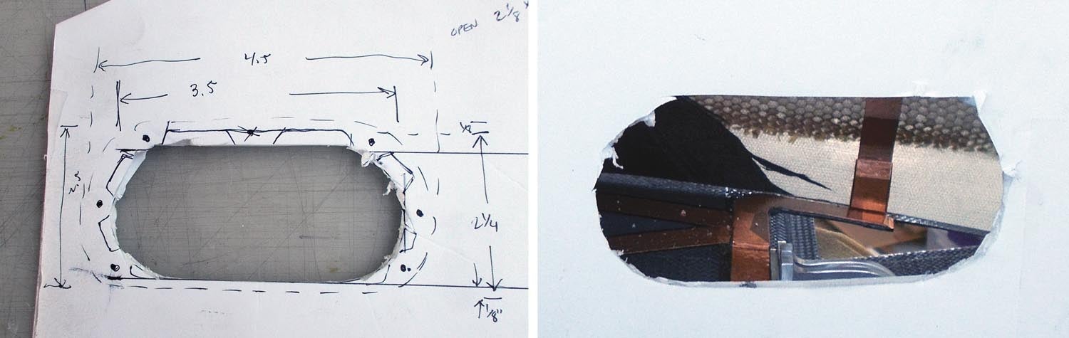
First, determine the size of the access hole. From a structural perspective, it’s generally best to keep holes as small as possible. If it’s just for inspection, it may only need to be large enough to fit an inspection mirror through, but if you need to put a hand inside, make sure it’s big enough. I like to print out a CAD model and glue it to some cardboard and make sure I can get my hand through.
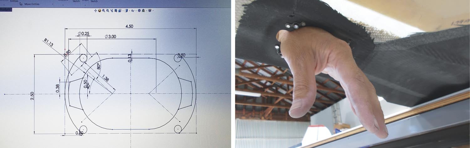
As previously noted, the hole is smaller than the panel since we need to account for the support flange. I recommend adding 3/4 inch around the perimeter of the hole for the flange width. You’ll want to ensure the edge distance is 2 to 2.5 times the diameter of the fasteners for both the panel and the flange, and if you are using bonded fasteners like Click Bonds, that the flange is sufficiently wide. The Click Bond nutplates I recommend (CB4009 floating nutplates) are 0.525 inch wide, so a 3/4-inch-wide flange is perfect.
Next, assuming you don’t have access to the original part molds, you’ll need to make a mold of the skin exterior in the region of the panel. This is fairly straightforward: Simply apply packing tape as a release over and about 6 inches beyond the edge of the desired panel location. Butter a layer of Bondo over the tape and slap a piece of plywood on as a structural backer.
When you pop this off, you’ll have a perfect mold of the OML (outside mold line) at the access panel location. (In the pics, I had access to the original part molds, so I was able to skip this step.) If there’s a takeaway to this article, it’s this: These types of small splash molds (as they are called) are super convenient for re-creating perfectly matching parts. You can also see splash molds in my previous article on composite sheared wingtips in the June 2023 issue.
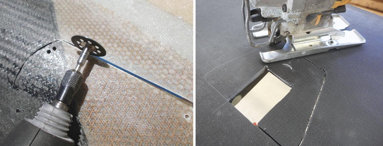
The next step is to cut out the access panel outer diameter (OD). Remember, this is the OD of the panel itself, not the hole, which is offset inward by the width of your flange. Depending on the situation, I’ve used (in order of personal preference) a Dremel diamond cut wheel, an oscillating multi-tool and a jigsaw. I prefer the Dremel, but it does throw up a lot of dust, which the multi-tool does not. Finish the hole to its final dimensions with a sanding block.
Making the Panel and Flange
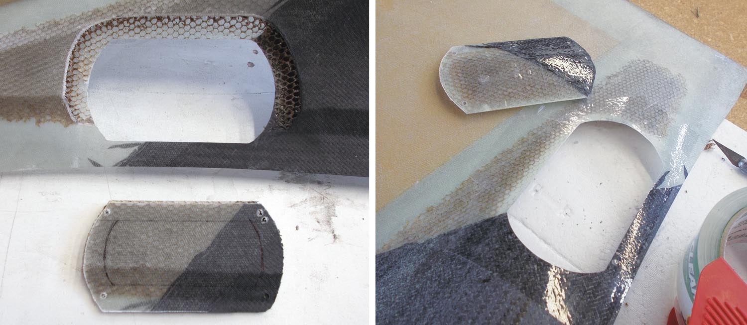
If you are careful, when you cut out the hole, you can save the leftover piece and use this as your access panel. Otherwise, you’ll need to fabricate one. This is where you’ll use that splash mold: Reposition it on the skin and use a scribe to mark the outline of the hole you just cut into the mold. You don’t need to make the scribe deep—even the lightest mark will transfer to the finished part.
Now take the mold, wax it three to five times with mold wax (I like Meguiar’s) and lay up a panel on it that has the same ply schedule as the skin itself. You should be able to get the schedule from the kitmaker. Otherwise, measure the thickness of the laminate (ignore any core material) and fabricate a panel with the same thickness. If you want to countersink the fasteners, you may need to add extra material to allow for sufficient countersinking material. Once cured, pull the part from the mold and trim to the scribe line.
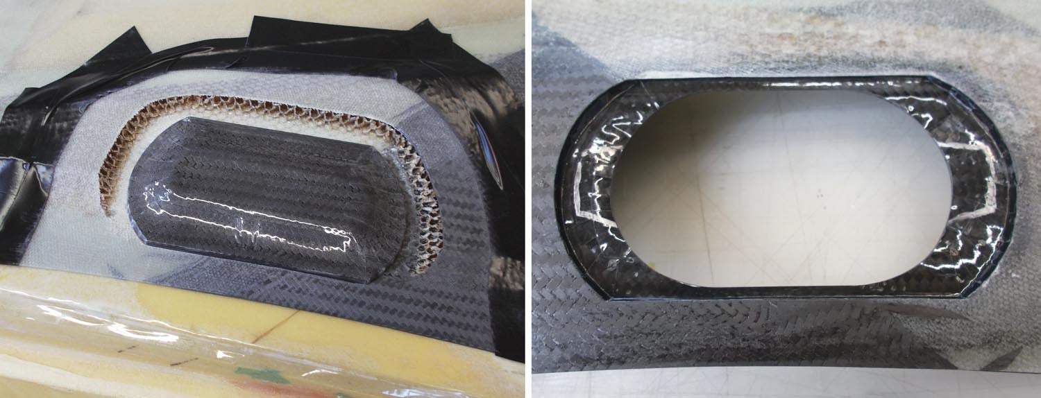
The next step is to fabricate the flange. Prep the skin by lightly sanding the skin interior about 1 inch out from the cutout and wipe clean with acetone. Release the splash mold with packing tape (don’t use wax or the access panel won’t stick) and fit it in place on the skin exterior. Release the access panel (both sides; again use packing tape here, not wax) and position it in place, securing it to the mold with double-sided carpet tape or 3M Super 77 Spray Adhesive. Lay up the flange with the same schedule/amount of fabric used to make the panel. After it has cured, remove the splash mold and access panel and trim the layup to the desired flange width.
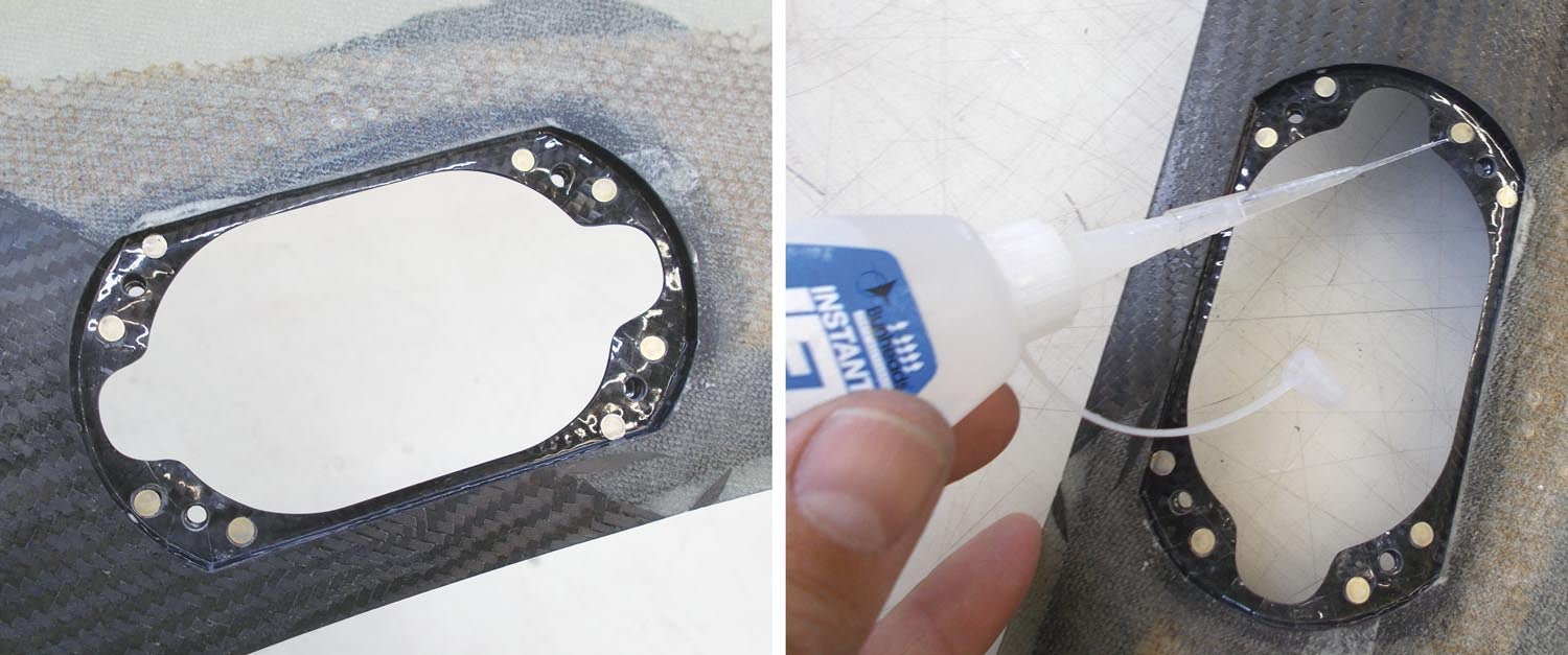
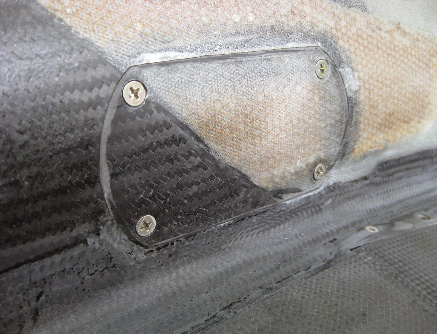
The final step is to attach nut plates to the flange. First, drill your fastener holes in the access panel itself. Transfer the panel to the skin and match drill the holes. You can now add nut plates to the rear of the flange. The pictures show riveted nut plates, but recently the Click Bond CB4009 floating nut plate is my preference. They’re a bit pricey but a lot easier to install. (You can find a large selection of Click Bond products at www.theflightshop.com, and I highly recommend perusing the Click Bond website www.clickbond.com—so many cool products that you never imagined existed!


")

