 Of the three landing/taxi light locations available to GlaStar builders—engine cowl, wingtips or leading edge—I chose the third option and decided to install a pair of Flyleds Triple Spotlights. It’s a fun project and I even learned a new skill.
Building the Wing Light
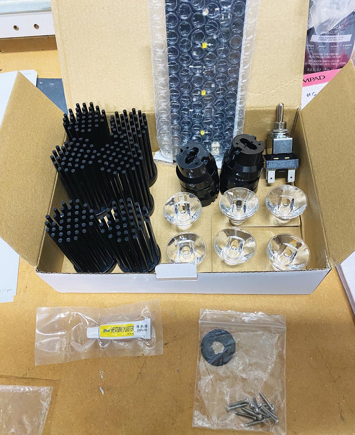
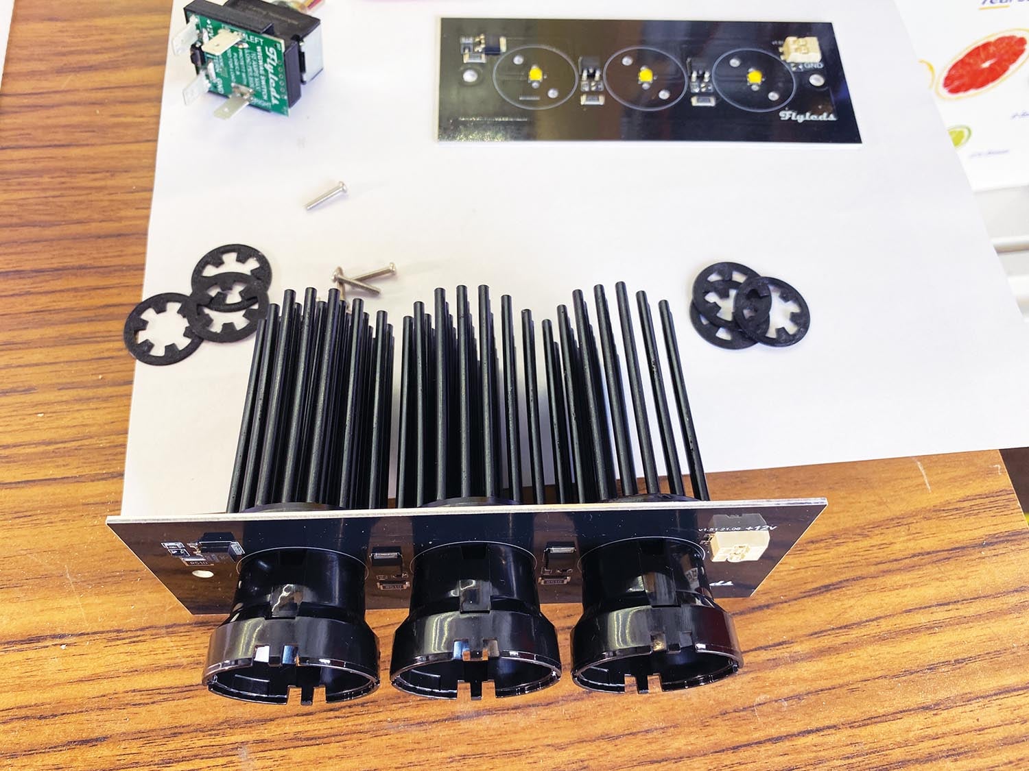
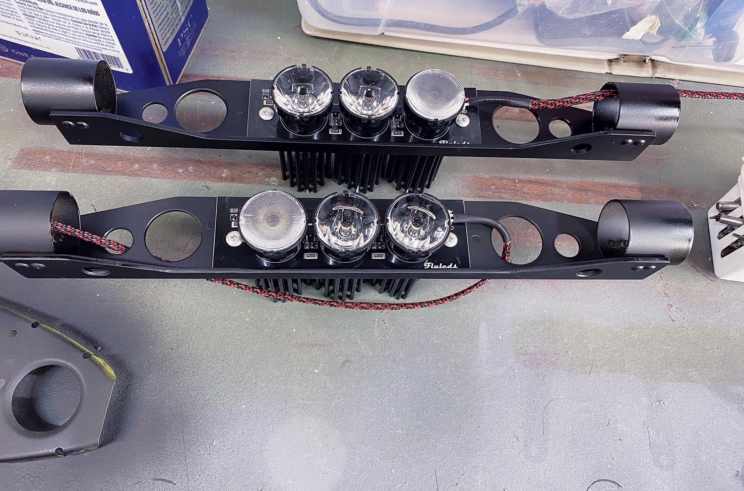
The Triple Spotlight arrives as a “some assembly required” kit from Flyleds, no more difficult to assemble than snapping a few Lego blocks together. The base for the spotlights is a 6×2.4-inch aluminum board with a printed circuit and three Cree LEDs on the front side. The back side is flat and unfinished—perfect for helping transfer heat produced by the LEDs to a mounting bracket. It has two mounting holes, and their location is my only gripe because they are too close to the “porcupine” heat sinks on the back when assembled and don’t leave room for a nut plate. The assembly kit includes a small tube of heat-sink compound that you spread thinly on the heat sinks and then sandwich the board between them and the three lens holders. Wait 10 minutes for the compound to set, snap the lenses into position and you’re done. Really simple and having you do part of the work keeps the lights affordable. The light kit is $139 per side.

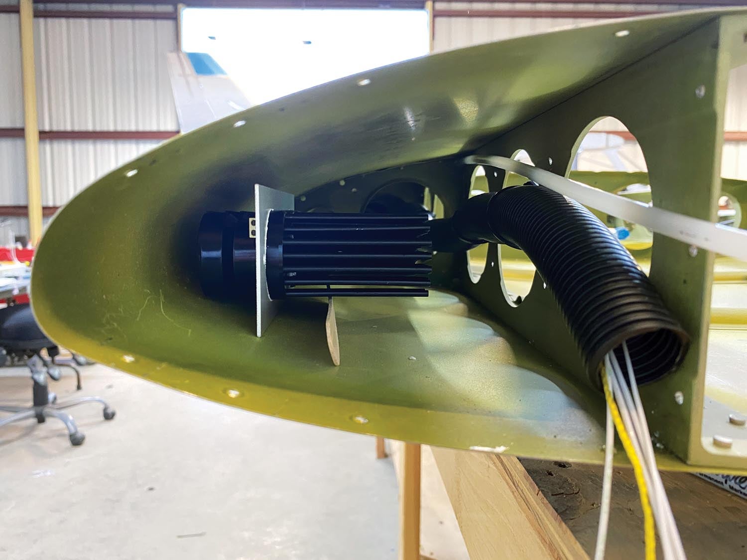
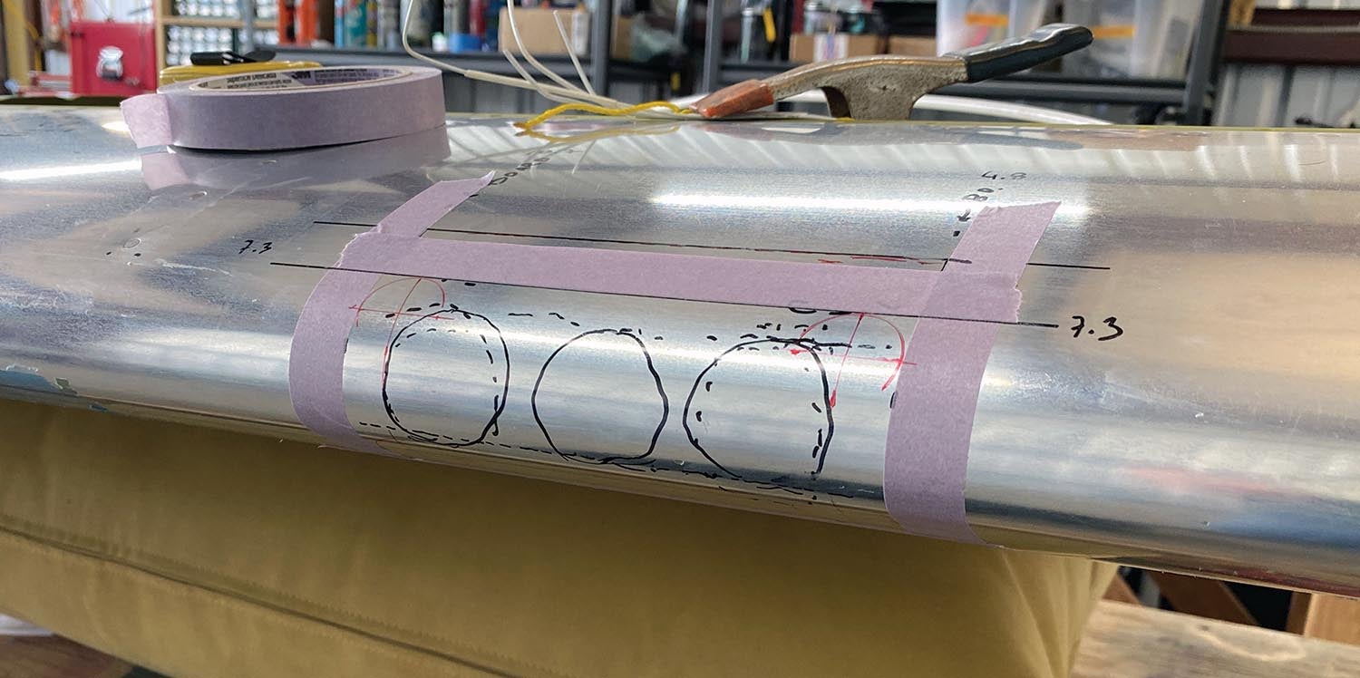
The aluminum board can be trimmed down to 1.6 inches high, which is great because I wanted to have a small aperture in the leading edge. I also wanted the light to be adjustable vertically, so I built a bracket that fits between two leading-edge ribs and uses the forward lightening holes for mounting. This approach lets me adjust the light without removing the acrylic lens. Anti-chafe tape between the tube and the nose rib helps make a tight fit and ensures that the mounting bracket won’t rattle around and enlarge the hole.
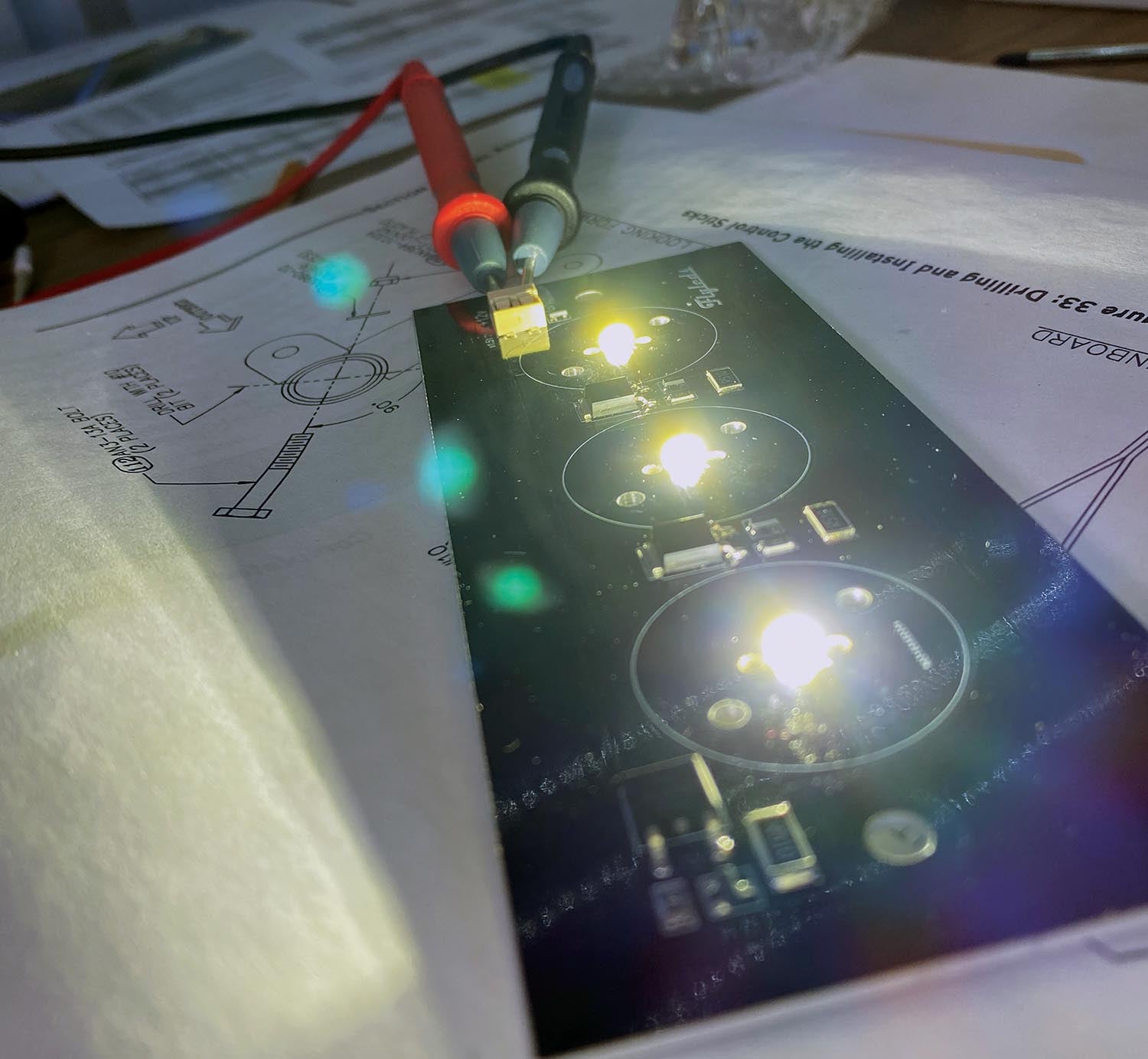
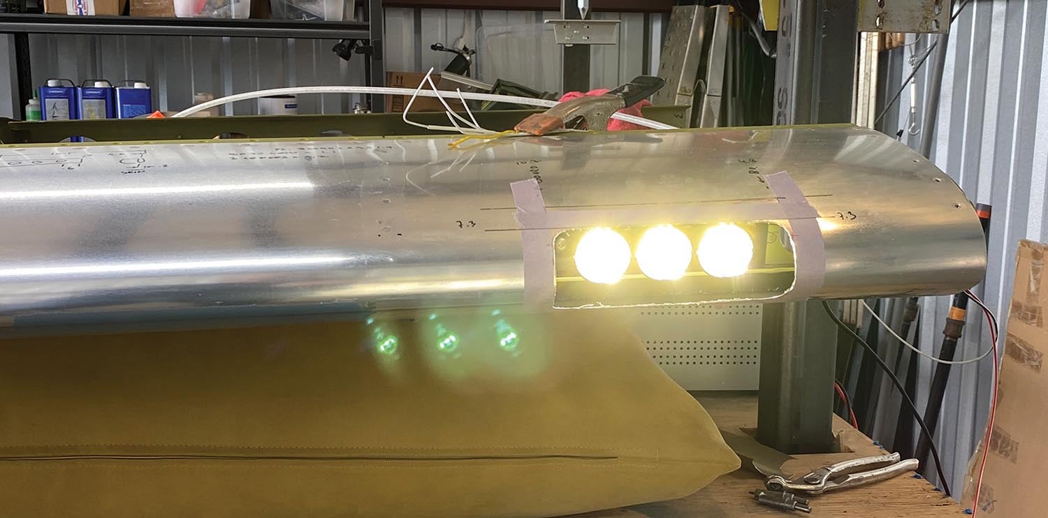
To keep the aperture small, I positioned the lights as far forward as possible, but that meant they would be close to the lens, so the smart thing to do was to test whether this would heat up the acrylic too much. Turns out it’s not a problem—I placed the lens right in front of the lights for 30 minutes, closer than they’d be in the final position, and the acrylic lens didn’t even get warm so I’m certain the LEDs won’t burn three holes in it. I also wanted to know if either acrylic or polycarbonate sheet would be damaged by a fuel spill, so I cut two samples and placed them in fuel for 20 minutes. Both came out unscathed, but since acrylic is less prone to scratching it became my material of choice.

I’d only made rudimentary bends in acrylic sheet before, just a simple 90° bend for a non-aviation project where the fit wasn’t critical, but now the lens needed to fit the profile of the leading edge exactly.


Attempt One
I held a small piece of 1/16-inch thick acrylic in front of a propane heater and within seconds it became soft and malleable. Great, I thought, this will be a piece of cake! Only to find out that when I scaled up the dimensions to the size needed, I could not heat the 5×8-inch piece evenly just by holding it in front of the heater. When one side got warm enough to start bending, the other was still stiff. When I turned it around, the soft side hardened. I tried placing the sheet over a steel pipe in front of the heater, but that proved unmanageable as well. I needed a mold.
Attempt Two
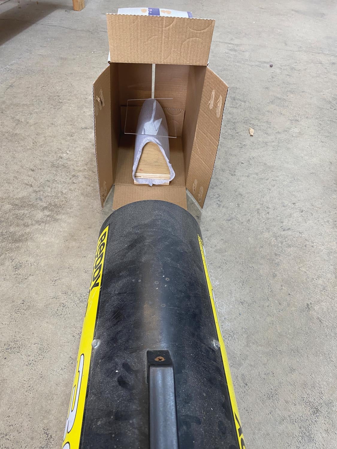
No compound curves are necessary for the lens, so I traced the wing’s leading-edge profile onto paper and then transferred it to two pieces of plywood. That gave me the base for the slump mold into which I screwed a 0.020-inch aluminum sheet, slightly larger than my lens. My naïve expectation was that I would blow some hot air over the acrylic, and it would simply fall into the mold. Fall it did, but one side heated up faster than the other, so one corner dropped in first. I tried fixing this by moving things around but again I could not get the part to heat up evenly. One side was soft while the other was stiff. I needed a better method.
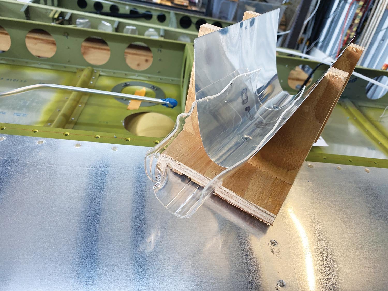
Attempt Three
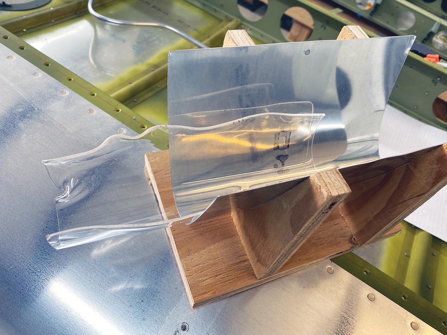
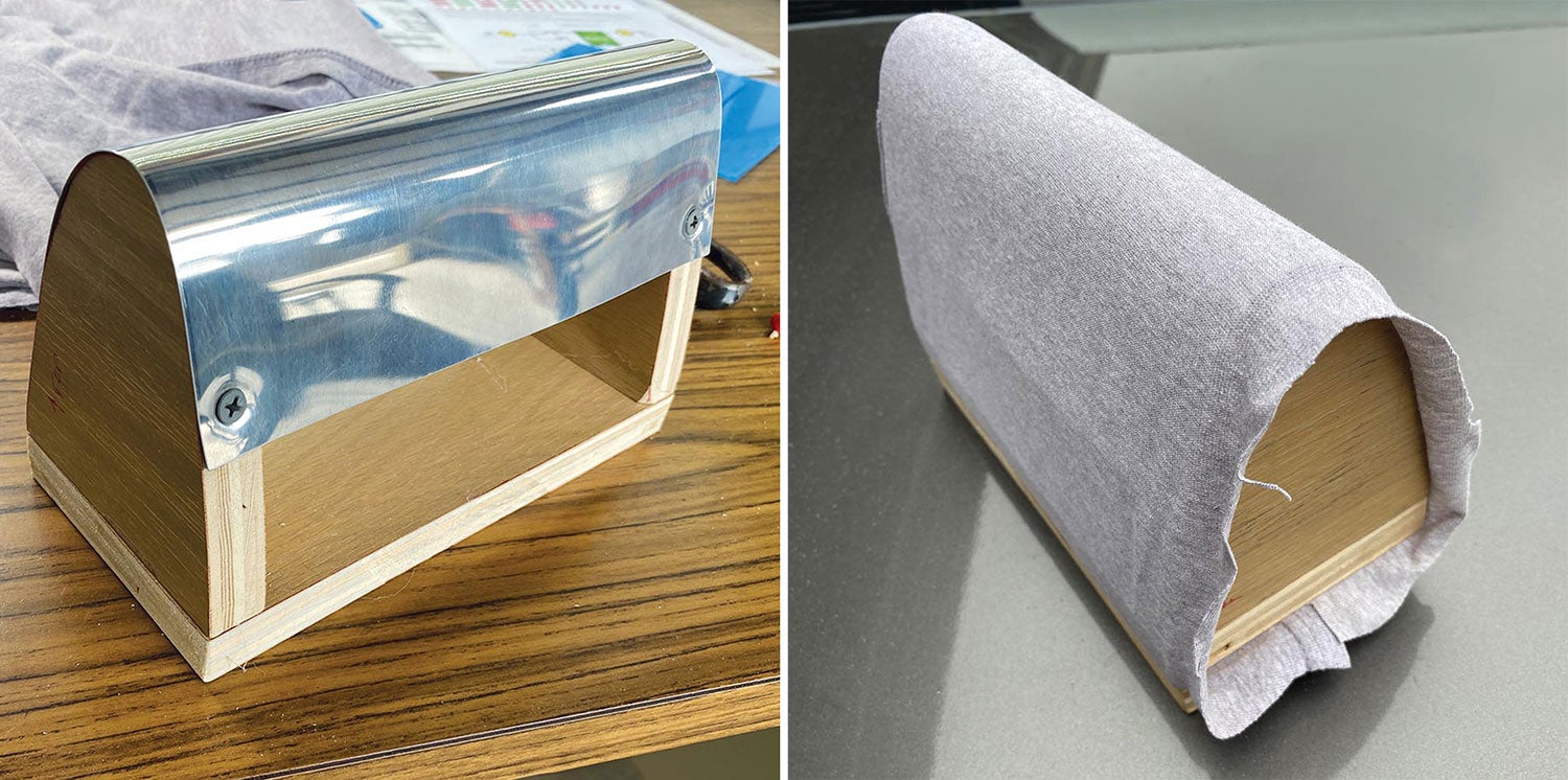
Drape molding! That’s how they do it on YouTube. I made a mold that was an exact copy of the leading-edge shape and repeated the heating steps from the previous experiment. Right away I could see that with this method I had better control over the part’s placement on the mold, but my heating was still deficient. I placed the mold and the flat piece of acrylic in front of the heater and when the material got soft, I helped it form over the mold. The problem again was uneven heating—the side closer to the heater would soften too much while the opposite side remained too cold to form. The hot side also started sticking to the aluminum part of the mold, distorting the optical quality. This wasn’t going to work—I needed a better heating solution.
Attempt Four
In one of the YouTube videos I watched, the protagonist built a heating oven on top of an old propane grill for a rally car’s windshield. I didn’t need anything that big, but a grill sounded like a good idea, so I snatched Marc Cook’s propane camping grill with an explanation that the acrylic can only enhance the flavor of his future steaks. He didn’t fall for it, but I offered him a couple of Twix bars and he surrendered the grill, err, forming oven. I was in business!
From the third attempt, I learned that there should be something soft between the mold and the acrylic piece so it wouldn’t stick, so I stretched an old cotton T-shirt over the mold. The first attempt at heating the acrylic on the grill was much better than the previous methods. I had a piece of cardboard on the grate and another piece of the cotton T-shirt over that and the acrylic on top. With the burners on the lowest setting the cardboard diffused the heat well and allowed the acrylic to heat up evenly. I was doing this by eye and watching the edges of the acrylic start to curl up for a cue that it was pliable. That was OK-ish but not good enough.
The experiment worked, though. I moved the acrylic from the grill to the mold and just set it on top, not really knowing how it would behave. It slumped over partway, but I could see that it would have to be forced into position if it’s going to take the shape of the mold, so I placed it back in my fancy oven for a second attempt. Meanwhile, the cardboard diffuser started to char—it was only going to be good for one lens. The acrylic was now hot enough and I again placed it over the mold, but this time I pushed down on the four corners with my gloved fingers. I was getting somewhere with this approach! The lens took the shape of the mold, but my fingers distorted it to an unacceptable degree.
Attempt Five
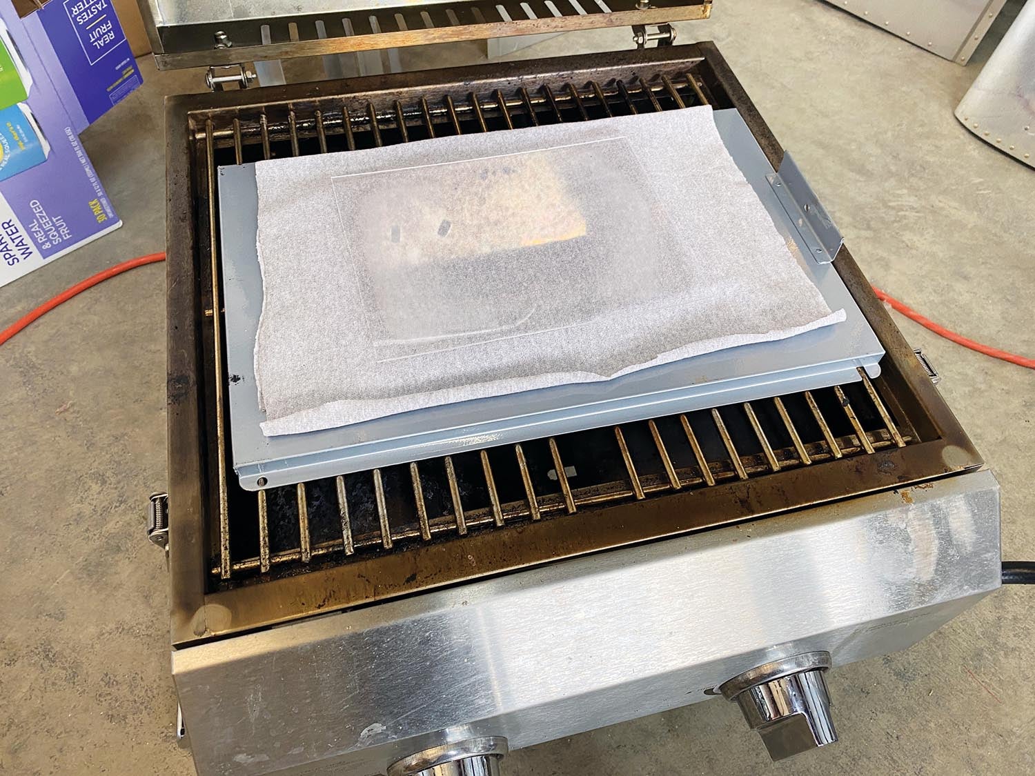
This is the one in which I conquer the acrylic sheet but fail on the shape. To avoid charring the cardboard, I stacked a sheet of aluminum foil on the grill, then the grill’s drip pan, and the cardboard wrapped in cotton. I laid the acrylic on top of that. I abandoned my unscientific guessing of the right moment to remove the acrylic from the grill and was now measuring the temperature with an infrared thermometer and looking for about 300° F. The heat-diffusing stack-up and the use of a thermometer proved successful. The acrylic warmed evenly and when it reached 300°, I put it on the form, but this time I helped it conform to the shape by draping another piece of the cotton T-shirt over the hot acrylic, pulling it down and holding it for about 30 seconds. Success! Or so I thought.
The lens looked great and I promptly took it to the wing and pushed it against the inside of the leading-edge skin. It didn’t fit well. My idea of forming it to the general shape on the form and then letting it take its final shape in the wing didn’t pan out because the lens cooled quickly and by the time I had it inside the wing, it refused to change shape. It would have to come off the mold and be the correct shape without any further forming.

Attempt Six
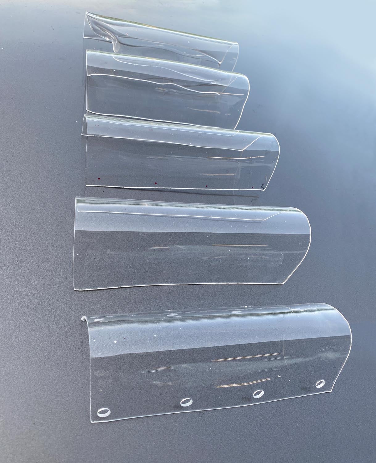
Accounting for the thickness of the acrylic, I remade the drape mold 1/16-inch smaller so that unlike in the fifth attempt, where the shape conformed to the outside of the leading edge, it would fit inside instead. I had perfected the method and the proof was the next lens that came out of the mold—it fit great! I made six pieces so that when they eventually get scratched, I’ll have ready spares.
Final Fit
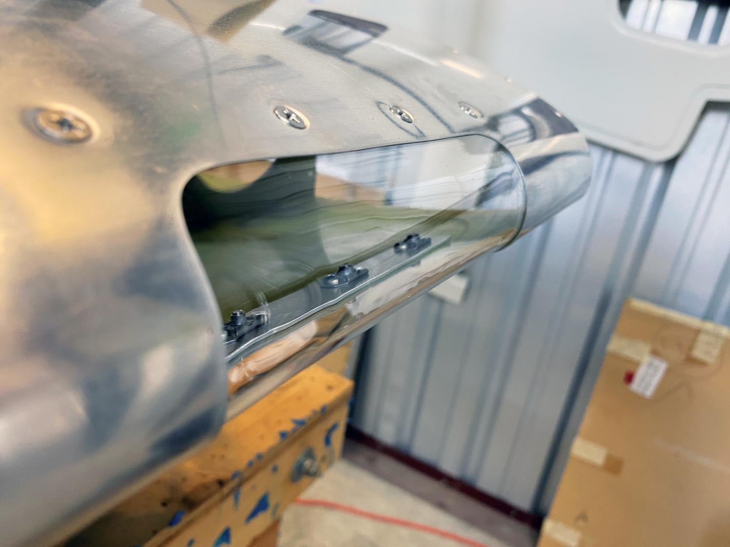
I purposely started with an acrylic sheet that was larger than the finished lens because in the early tests I could see the edge curling slightly—enough that it would ruin the flush fit against the inside of the wing. So when I was done forming the lens, I trimmed it to final size on the bandsaw fitted with a metal-cutting blade.
The leading-edge skin is dimpled for #8 screws and the lens is held in place by a piece of aluminum bar to which I added nut plates. I drilled holes in the acrylic large enough for the dimple to fit inside without putting any stress on the acrylic—it is held in place entirely by clamping force between the bar and skin.
This was a fun project that required me to learn how to form a simple shape in acrylic. My GlaStar is a trike, but as useful as it is, the adjustable light would be even better suited to a taildragger, where it could be pointed straight for landing and down for taxi by a small servo. Fun stuff for Experimental aircraft.


