Fiberglass composite is not my favorite subject. Of all the airplane projects that passed through my shop, my favorites are made of wood. They go together like big model airplanes, using tools widely available at the hardware store, smell nice, and finish beautifully. If it weren’t for the rising cost of wood material and the need for a dry hangar, I might be describing a nascent wooden wonder right now.
But alas, the recent plundering of my medicine cabinet for anything to relieve itching on my feet should remind even the most forgiving reader that fiberglass is less pleasant than wood and should never be sanded while wearing sandals—might not want to breathe it, either.
All manufacturing comforts aside, almost anything is possible with fiberglass, and my little Q200 project, at last mechanically sound, needs a cowling. The original cowl fits tightly around a VW powerplant with no room to spare. Early builders took great pains with baffling before the little engine would cool properly. Replacing the VW with the more reliable, powerful, and expensive Continental O-200 demanded a modification to accommodate the low-slung carburetor and oil tank. The Continental’s extra length required a hole in the firewall, into which the magnetos and accessory drive fit snugly, boxed up over the pilot’s feet. Easier to do this than elongate the entire cowl and move a wing forward to compensate for the shift in CG. The cowl is very tight, and efficient cooling remains a challenge.
Balancing Act
The amalgamated rotary in my airplane is seven inches longer than an O-200, but weighs about the same. It is too large at the rear for anything to protrude aft of the firewall, thus creating a forward CG. A large battery mounted aft of the baggage area compensates for this and provides ample ignition current in the event of an alternator failure.
There’s no hope at all of fitting everything under the original cowl. In fact, packaging requirements are the major difficulty of this engine installation. If I had to do it all over again, I’d pick a larger airplane. It’s a bit disconcerting to grind into a beautifully formed cowl, gouging big openings for a prop flange and gear reduction, then (gasp) a starter, oil tank, radiator cap, muffler, and more, all the while hoping for something streamlined and reasonably good looking.
At the beginning, the cowl looked like Swiss cheese before it could span the engine and engage the firewall. Worse, the starter motor protruded well above the original cowl profile. I imagined an ugly blister to cover it. This image is uncomfortable, even now. The Q2 is among the world’s most beautiful airplanes—it’s a terrible shame to spoil the lovely lines with a massive wart on the nose. I exchanged the original 7-inch spinner for one with a 14-inch diameter. The larger spinner opened the cowl enough to cover the starter at the expense of a slightly upturned profile. It’s not my favorite look, but better than a wart.
Building the Plug
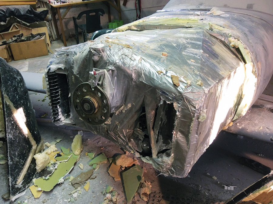
The first steps included wrapping the engine with enough tin foil, plastic, and duct tape to withstand direct attacks from a power sander, then fitting the holey cowl over everything. The old cowl became the basis for a new one with better proportions. There simply wasn’t a way to actually use any part of the old cowl in the final product, but it does ease the plug-building task.
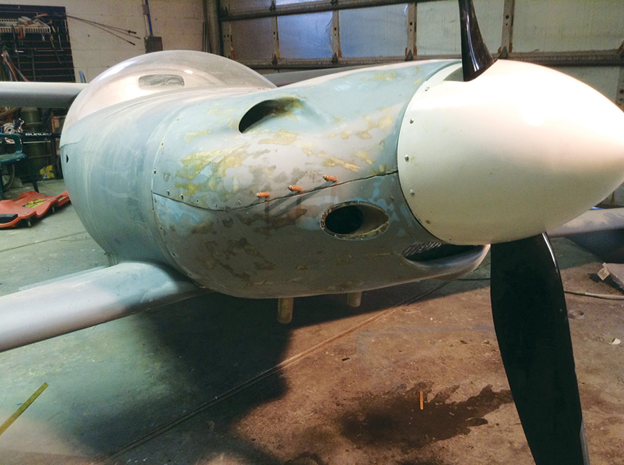
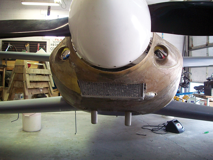
Final iteration of the original cowl. Middle intake sanded off, then lensed for a landing light. New radiator cooling intake just beneath the spinner.
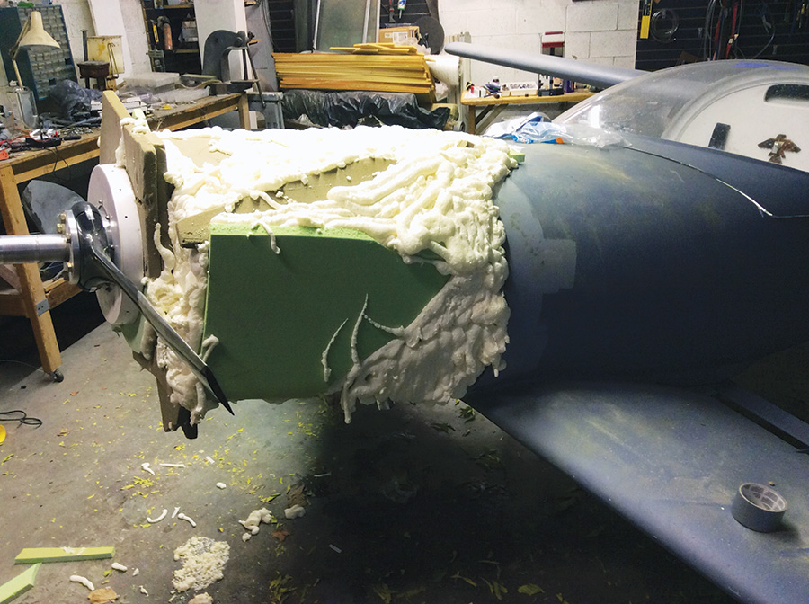
Into the many holes and around the protrusions goes a great deal of spray foam. I have both good and bad comments about this. The gap sealant foam available at the hardware store is very sticky and useful for gluing larger blocks of foam together. It remains fairly soft when dried, however, and sands quite poorly—leaving unpredictable voids and inconsistent densities. All that aside, it is great fun to squirt from the can and, as usual, I left too much of it exposed on the plug. Two-part foams, also available in cans, work better and are way easier to shape, but cost more.
Don’t sweat the shaping material too much. Anything will work, as long as you prevent it from sticking to the fiberglass layup that follows. I once formed a custom-fit stick grip by squishing a bunch of highly catalyzed chopped fiberglass goulash in my hand. Of course I wore a glove, but didn’t anticipate the heat generated from a rapid cure. Plunging the whole thing under a flow of cool water helped manage the temperature until it set enough to put down. Masonite, wood, cardboard, Plexiglas, clay, steel, silicone, wax, plaster, and even papier-mch can work pretty well to shape fiberglass. It’s not rocket science.
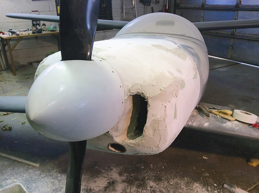
With that frame of mind, I needed something simple to make a shape around the engine. Not interested in mass production, the shape, or plug, could be quite crude. I used the old cowl to make up the bulk of the shape, then filled in the gaps with spray foam, which acquired some detail with the help of a hand saw. Over this goes a bunch of quick-curing drywall mud, followed by a lot of detail sanding.
A great deal more work might polish the plug to a shine, then pull a female mold from this, then the final product from the female mold. I skipped the female part with good results. Too many questions remained about the engine and its cooling needs to go to the trouble of a more elaborate mold. This proved, in the end, to be wise.
Fiberglass Layups
Coat the plug liberally with release wax and polyvinyl alcohol (PVA). Laying fiberglass over the plug is very simple, like spreading a tablecloth on the dinner table. Resin spreads easily into the fabric with the aid of cheap brushes, squeegees, and a small paint roller. When it cures, it may, or may not, come off the plug easily. It’s hard to have too much mold release agent. I’ve had to sand out remnants of mold materials from the fiberglass just formed on a few occasions—a messy pain, but not the end of the world.
The cowl just formed ended up too short for the propeller. I’d constructed the plug to meet flush with the prop flange, using a round piece of plywood cut to match a spinner back plate. Unfortunately, the electrically adjustable Ivoprop (purchased later) required a mounting extension, leaving an ugly gap between the cowl and spinner. With the cowl in place, I simply crammed a bit of sheet foam into the gap, shaped, sanded, and glassed the whole thing in a couple of afternoons. After some sanding of the finished product, we were back in business.
Clay Time
Now the cowl needed scoops for cooling and induction. Read carefully, because what follows is the Holy Grail of quick fiberglass modifications:
The local art store supplies bulk quantities of oil-based sculpting clay. I bought 20 pounds of it for $60. It molds well to any surface and takes any shape you like. Use patience, a straight edge and flexible scrapers until the clay surface becomes very smooth. Best of all, no release agent is needed for the clay itself, because of its oil content.
Simply wet out the fiberglass fabric over the clay, let it cure, then remove the part and dig the clay out for reuse. The part itself cleans up well with MEK and a wire brush. I formed wheelpants, wing fillets, manifolds, seat pans, intakes, and NACA scoops with this method. Get enough clay, and you could quickly mold an entire plane! Besides, who doesn’t like playing with clay?
A soda can makes a fine cylinder for molding a short fiberglass intake. Simply coat the can with wax, and wrap it with a couple layers of resined glass cloth. When cured, just crush the can and peel it away from the glass. Clean everything up—lots of sharp edges—and carefully position the intake in the cowling, gluing it in place.
After the glue cures, use clay to shape the external side of the intake, wait for that to cure, clean it up, and glue in place. You get the idea—make a mold, mix resin, set fabric in place, and wait. Glue something, more waiting; another mold, more waiting. On a cold day, you might wait forever. Fiberglass resin cures better in warm temperatures.
The most efficient builders get several parts curing at once and make rapid progress, despite the time waiting for resin to dry. I’m not very efficient and occupy my time with other projects. The pace of this project has been very slow—like a glacier, sometimes. Nevertheless, having glue drying while I am busy doing something else is a little like doing two things at once.
Engine Modifications
The engine required major changes before the modified cowl saw any use. A reorientation of cooling systems meant new intakes and heavy cowl modifications—this would be cowl number three. More Swiss cheese and more engine components sticking out into the breeze. Except this time, the cowling could be patched and modified—not quite starting over.
This is a good illustration of the forgiveness of fiberglass composite. You may change your mind many times during construction without much ill effect. Don’t be afraid to make multiple parts. Many of these will be molded in place on the original cowl, then removed, cleaned, and re-bonded in place, like so many parts of a plastic model. With care, modifications gain little, if any weight, despite many layers of overlapping ideas. Just plan on a lot of sanding. Excess material is never a good idea.
The new cowling acquired an intake to fit the low-mounted radiator, a nostril to guide air through an oil cooler, and a convoluted induction pathway through a filter. The intake air required a chin bump for smooth flow, an ugly consequence of radiator positioning. Worse, in a moment of unbridled passion, I carved away and re-formed the upper cowl in anticipation of a relocated starter motor. The new motor did not fit (long story), and the cowling grew an ugly wart to cover the old one. One nostril and warts on nose and chin left something to be desired in the looks department. I was almost happy when the cooling proved to be entirely inadequate.
As a side note, please understand that I prefer to prototype ideas in the flesh and try them, rather than kick things around on the drawing board. This leads to a lot of failures, as illustrated above, but produces the occasional spectacular success. Many do not share this philosophy and focus heavily on a drawing board or CAD program before cutting any material. I simply enjoy making parts and trying fresh ideas. Best not to be discouraged if the first—or fifth—attempt fails to please.
Cowling Evolution
The first attempt looked a lot like the original cowling, with radiator and oil cooler located behind intakes to either side of the spinner. This proved challenging, in that airflow and plumbing were not efficient.
A second iteration placed the radiator under the engine with the oil cooler on the firewall. Although very efficient from a plumbing perspective, the airflow left much to be desired. In particular, the radiators required too much thickness for adequate cooling. A short experiment with a book-shaped radiator proved unworkable, leading to the final configuration of large heat exchangers along either side of the engine.
This last major alteration of the engine actually worked well without a cowling. A very large radiator mounted on the side, with a corresponding oil cooler on the other side, required a total rethink of the cowl. Cooling air would have to pass between the engine and radiators, then exit through gills on the side. The cowl would be more complex than any thus far. As I thought about this, the new cowl would require a female mold.
More foam and drywall mud, carving, and sanding. A lot more. The pictures are self-explanatory. Avoiding any use of the original cowl enabled some creative liberties aft of the firewall. That upturned nose faded by extending the cowl profile aft almost to the canopy.
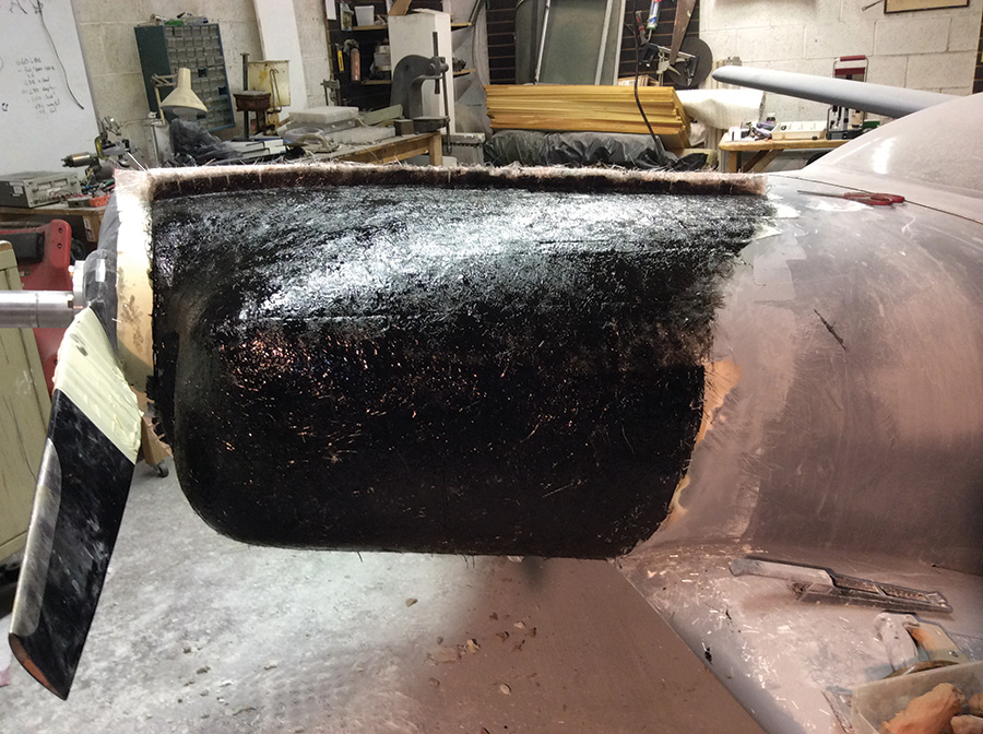
Some high-build primer helps to smooth the plug’s surface, with occasional clay smeared into the low spots. Some PVC corner angle from the hardware store, cut to bend around the plug, makes a suitable divider for the left and right halves of the mold. The mold itself begins with a thick coat of gelcoat—the black stuff in the photograph. Gelcoat is available in many colors and creates a beautiful surface against the plug. Into the gelcoat goes reinforcing glass fibers, which are then thickly overlaid with glass mat and resin. Weight is not the issue here, stiffness is. The mold needs to rigidly hold its shape. The PVC divider can be removed once the glass cures, forming a flange used later to secure the two mold halves together. The other half of the mold is formed the same way, after spreading more wax and PVA.
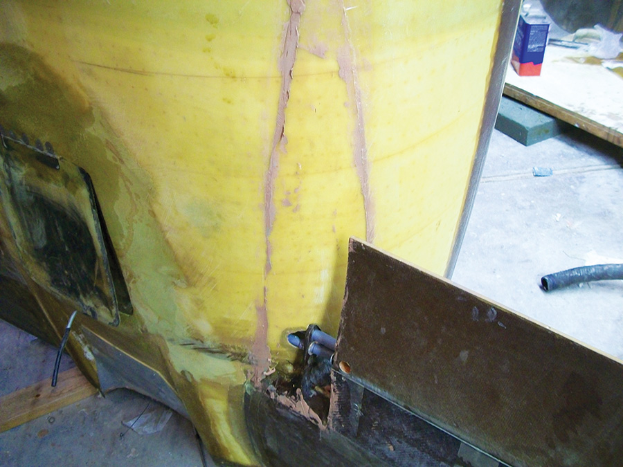
Clay residue still remains on fuselage after forming wingroot fairings. It’s easily cleaned up with MEK and a wire brush.
When cured, the mold itself is not much to look at. This one in particular is intended for a single cowling and is a bit crude for any sort of mass production, but it works quite well. Imperfections in the mold may be sanded smooth, much like the plug was shaped earlier. The mold does not require fancy aerospace resins and cloth, either. Simple polyester resin, glass mat, and no major concern for weight add up to a fairly inexpensive mold. This one cost about $150.
As a side note, it seems every modification to this airplane has cost about the same. Starters, plumbing, trim systems, fairings, control, and instrumentation modifications could fill a few pages, and each listed out just north or south of $300. One of the many names for the airplane (some of them unprintable!) is “The $300 idea.” No surprise when this latest cowl, mold and all, rolled out right at $300, too.
Doors and Access Panels
A female mold simplifies forming detail parts of the cowl. The doors and access panels, for example, are very easy.
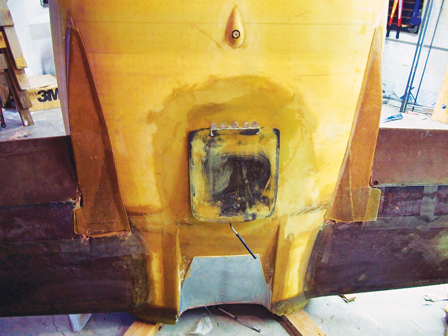
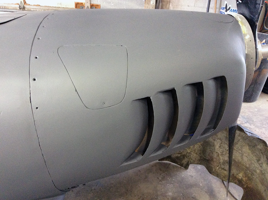
Mark the door shapes and position on the mold, then wet out a few layers of fiberglass over the marks. Before removing the cured glass, drill a few holes through it for Clecoes. Remove the cured layup from the mold, cut it to the shape desired, and Cleco the panel back in place. It is simple then to smear release agent on the panel, along with the mold, and lay up the rest of the cowl right over it. In this way, the doors and access panels are cast in place. Later, they separate from the cowling for the addition of hinges and a latch mechanism.
The cowling itself may be formed in sections, removing each from the mold for shaping and cleanup, then placing it back to form the next section. This results in molded seams for a perfect fit.
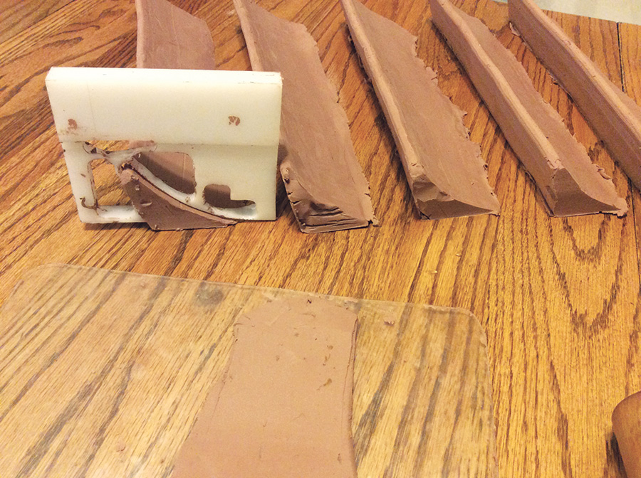
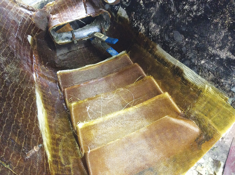
I used clay to make the cooling gills. I began shaping the clay on my kitchen table. It went slowly until I cut a little extruder from some high density plastic. With care, this tool could be dragged over the clay, assuring each piece met a uniform shape. These clay steps were fitted into the mold then fiberglass was wetted over them.
As the cured parts leave the mold, there are a lot of sharp edges, maybe several pinholes, and larger gaps here and there. These are easily fixed with sandpaper and fill material of choice.
If you sand a hole in the cowl, simply push clay up through the backside, shape it smooth, and patch more fiberglass over the top. That’s about all there is to it—a simple method that involves a great deal of work and elbow grease (but not a lot of cost) and is limited only by your imagination.
My imagination sees a fish—The Cosmic Fish. I sure hope it flies.

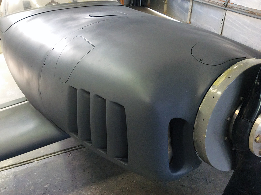
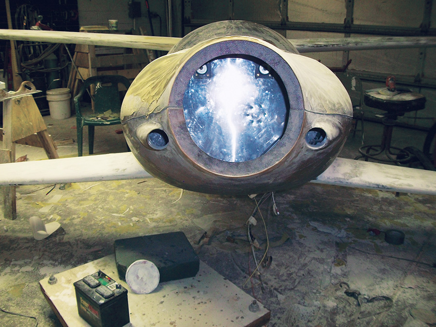


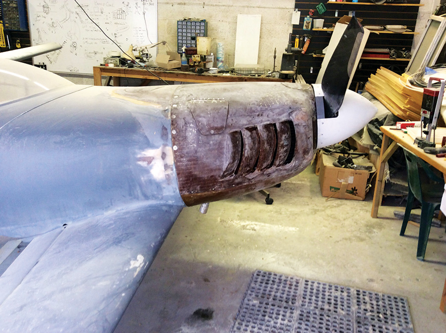

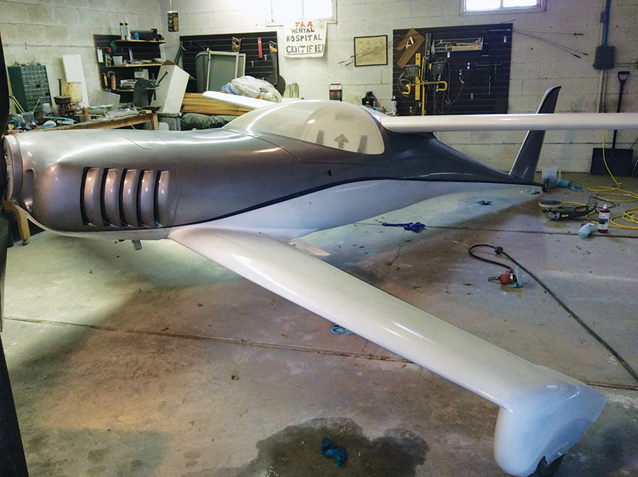




Wow! A lovely end result, with a much better engine!
Not many of those planes around nowadays, and fewer and fewer as time passes.
Years later this story still captivates.