Like every homebuilt airplane since Wilbur and Orvilles, our KK-1 was taking longer to build than we had envisioned. But now that the static-testing was out of the way-we did not intend to test the fuselage-we pressed on. (In case you’re just joining us, the first part of this series appeared in the December 2008 KITPLANES, and we described the static-testing process in the January issue.) The lessons of the test wing helped immensely, and the flight wing was finished in about three months.
The fuselage begins with a stainless-steel firewall and an aluminum keel. The keel is built from bent sheet aluminum and forms three sides of a box running from the back of the firewall, between the pilots legs to the forward face of the mainspar. The top of the box gets lower as it moves aft, and the whole thing is open on the bottom of the fuselage.
Behind the seat, the fuselage is a simple cone. A couple of bulkheads of pressed aluminum provide the shape, and single-curvature aluminum skins rivet together to supply the strength. Curving longerons, made from 6061-T6 aluminum angle, run from the firewall to the rear bulkhead.
The control system is very much RV, with a swinging control column under the floorboards that propels pushrods to the ailerons and elevators. Everything is on rod-end bearings-there are no cables, no pulleys-and it runs as smoothly as you could want.
The Engine Arrives
Meanwhile, Mel Ellis, our engine man, had been busy in his shop, and just before the flight wing was finished, he showed up with the completed engine. Using a VW in an airplane presents some geometric challenges. Common aircraft engines use an updraft carburetor mounted underneath the engine, but the VW has its intake ports on top of the cylinders. In the car, the carb is mounted on top and short intake runners take the fuel/air mixture to the cylinders. We wanted the carb on the bottom of the engine so we could use a gravity-feed fuel system and eliminate the need for a boost pump.
The exhaust is another problem. Airplane engines have their exhaust ports on the bottom of the cylinders, so stub pipes can go almost straight down and join an exhaust system that usually exits underneath the fuselage. The VW exhaust ports are aimed in the horizontal plane. Those experienced in VW airplanes counsel using the lightest propeller possible and avoiding prop extensions-thereby reducing stress on the crankshaft. That means the propeller plane is pretty darn close to the front of the engine, and that front exhaust pipe has to make a sharp 90 (or more) bend to avoid interfering with it.
These problems have all been tackled by other VW designs, so parts are available. Ellis used induction runners and tubing from Great Plains to fabricate an induction system that suspended a small Zenith carburetor under the engine. He made a four-into-one exhaust system that joined just aft of the carb.
When he finished assembling the engine, Ellis mounted it on a test stand, bolted on an old wood prop for a load, and fired it up. He was pleased to find it ran well from the start. He delivered it while we were building the flight wing, and on many evenings I found myself staring at it over in the corner, while my hands did familiar jobs on the wing.
Although I was perfectly happy with the basic engine-his craftsmanship was excellent and it matched our requirements quite well-I suspected that keeping the VW happy would be the area where we had the most to learn. I thought wed find little problem with the aerodynamics, strength or flying qualities of the airplane, but things like getting the mixture right (we worked up a rudimentary mixture control for the Zenith carburetor, which normally doesn’t have one), carb ice, heat inside the cowl and throttle lag due to that long, complicated induction system could potentially do something unexpected. I vowed that we would be extremely careful flying behind this engine.
Moving On
With the flight wing behind us, construction accelerated. We made the parts for the forward fuselage just like we made the wing parts, and soon we had the fuselage, between the firewall and the mainspar of the wing at least, assembled. A spare firewall was mounted on a roll-around engine stand and we hung the engine on it. I spent the next months of evenings designing and making engine-cooling baffles. After several tries with cardboard patterns, I had a system that looked good, directing all the cooling air either through the cylinder fins or the oil cooler mounted on top of the engine case. Baffles for the VW seem to be sort of a black art, but I was convinced that this system, based on what Id learned on several Lycoming installations, would be at least as efficient as any VW system Id seen at fly-ins.
Cowlings. Tricky little buggers. On most one-off homebuilt airplanes, the usual technique is to hang the engine on the airplane, plastic bag it, cover it with foam, carve the foam to a cowl shape, glass and wax the foam to make a plug, make a fiberglass mold of the plug and then make the fiberglass part.
My building partner Ken Krueger had a better idea and came up with a solution that ended up being one of my favorite parts of the whole project. He used several tapering metal strips that, when curved until their metal edges met, formed a compound-curved surface. Actually, if you look at it closely, it is faceted rather than truly curved, but the difference is so subtle that its hard to see.
My original thought was to learn enough metal-forming skills to make a metal nosebowl and mate it to the front of the cowl. Id seen Kent Whites amazing work on the Hughes Racer and some exceptional work on a local Bellanca replica, so I knew there were people who could make metal do what I wanted it to do. Id just have to learn how. A few attempts at making the nosebowl from shaped aluminum showed me that this is not a beginners project. The compound curves and reverses call for skills that I just didn’t have. Rather than hold up the project, I decided to punt and make the nosebowl from (whimper…) fiberglass.
Sand, Sand, Sand
I mounted the cowl on the forward fuselage. The open hole in the front was a floppy oval-it looked like a big basking shark. We defined the shape of the opening on the computer and made a template in eighth-inch aluminum plate. With this fastened into the front of the cowl, I glued a big block of dense foam on the front and proceeded to carve away everything that didn’t look like a KK-1 nosebowl.
This brought about one of the stranger moments of the project for me. Memories can be surprisingly powerful. I don’t care to recall much about my high school years-lets just say surfing was the best part of that time in my life. And some of the best times surfing were shared with a neighbor kid who is still my closest friend. Not content with just riding waves and messing up the seats in our parents cars with surf wax and saltwater, we spent a lot of time building surfboards in my parents garage, working with foam blanks and fiberglass cloth. Now, 45 years later, I found myself again with a few Masonite templates, a block of high-density foam and a Stanley Surform. Suddenly, even though I was a gritty, sandy mess standing in a hangar 50 miles from the nearest ocean, I could taste saltwater and groan through the headache shock of cold liquid as we paddled out into the black predawn. In the background, I could hear my dad muttering about the smell of resin and the mess in the garage but never telling us to find somewhere else to work. All that was a lifetime ago now, but for a few moments, how I missed it! (I also found that you don’t want to wipe your eyes with a wrist covered in foam dust.)
Eventually I had the shape I wanted. I glassed it with three layers of 8-ounce cloth, sanded the result smooth, filled and sanded the little bubbles, and finally waxed it and covered it with mold release. I covered the plug with four layers of 8-ounce cloth and epoxy resin, which turned out to be barely enough to make a good mold. With a few plywood supports glassed to the back it sufficed, and I laid up a three-layer nosebowl inside it, using West Systems epoxy. In the end Id made a serviceable nosebowl, but with a large investment in time and a surprising amount of money. If Id had the skills, I could have made it in metal for about three bucks in less time.
Way Back: The Aft Fuselage
While I was making a nosebowl out of a big mess of foam and fiberglass, Krueger finished design work on the aft fuselage-the tailcone and aft cabin area. I pressed out the bulkheads around form blocks-a process identical to making wingribs and tail parts. Krueger had developed a way to bend J-stringer right on the edge of skins rather than make separate parts and rivet them on. In four or five evenings, wed made the parts and riveted together the aft fuselage, which weighed less than 25 pounds, at least the part of it below the main longerons. We stuck the aft fuselage in Kruegers Isuzu Trooper and hauled it to his home, where he joined the cabin section, inserted the longerons and, with help from his wife, Susan, riveted on the top fuselage skins.
At this point we were into early 2005. The fuselage was in Kruegers living room, the wing was in my hangar above my RV-6 (where it stared balefully at me whenever I went flying), and the firewall forward was in my shop. Both of us were getting to the point where we really wanted to put the beast together and fly it, just to see what we had. We turned up the wick under our work sessions and began to tackle the details. We mounted the stabilizers to the tailcone and set the elevator stops. That gave us the dimensions we needed to build the aft elevator pushrod-and a whole lot of other small things, none of them difficult.
Where the Fuel Goes
The 22-gallon fuel tank was the source of one of our few real design discussions. We wanted it high to permit gravity feed to the engine; keeping it in the fuselage meant there would be no connection to undo when the wing is removed. This component in our airplane does a lot more than just hold fuel. It serves as the rollover protection for the pilot, because it is the only part of the aircraft structure that is higher than the pilots head. It must support the shoulder belts, too. Normally, these would be anchored on the longerons or somewhere in the aft fuselage, but there is no good opportunity to get there when the tank is in the way. On top of this, the tank skin is also the outside skin of the airplane.
I was not comfortable trying to make this one structure do all of these jobs. I particularly did not want to have the shoulder belts strapped to the forward face of the fuel tank. It seemed to me that if the worst came to pass and the belts were subjected to the force of a body (probably mine!) slamming forward against the shoulder straps, the tank might rupture. For Krueger, however, getting a single structure to do all these things was satisfying-engineering elegance, as it were. He took the time to walk me through the numbers and forces involved; as usual I came around to his way of thinking and realized that by the time enough force had been exerted on the shoulder harnesses to rupture the tank, I was probably beyond caring anyway.
The only problem was that, to support these loads, the forward bulkhead of the tank had to be formed from heavy 0.063 aluminum. Bending metal this thick requires a generous radius, which in turn makes fitting parts close enough for prepunched holes to match quite difficult. In fact, we had to flute deeply between holes in the 0.063 flanges, and ordinary fluting pliers would barely make a mark, let alone a flute. We ended up using the end of an 8-foot hydraulic press brake that we carefully adjusted for depth. It was certainly the biggest fluting pliers Ill ever use!
It took only three long evenings to mix several glops of tank sealant and rivet the tank together. A simple aluminum tube serves as a vent line, and a plastic tube run top to bottom on the forward face of the tank became a sight gauge. The flush filler cap is right out of the RV parts bin.
Its Got Legs
The KK-1s nosegear leg was a sturdy, probably excessively so, affair. Fundamentally, its a bent steel tube. At the upper end it is welded to a cross tube, which fits between the inside faces of the tunnel that runs down the center of the fuselage. Steel flanges on the ends of the cross tubes are riveted to the tunnel sides. The idea is that the cross tube serves as a torsion bar, which will help absorb and damp any forces that the slightly flexible gear leg cant. The whole assembly turned out heavier than wed originally estimated, so we fitted a light composite Azusa nosewheel and a Lamb tire in the welded aluminum nose fork.
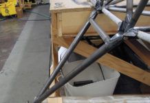
The maingear leg is simply tapered steel rods plugged into a tubular truss bolted to the mainspar. The lower end is bent and threaded to become the axle. The Azusa wheels are crude, but ran true when we learned the trick of assembling them on the axle. We originally planned simple cable-actuated mechanical brakes, and we had actually bought a set. We ran into problems trying to figure out cable routing from the rudder/toe brake pedals to the mainwheels on the wing. After looking at all the pulleys and fairleads we were going to need, we decided it was easier, albeit more expensive, to install hydraulic brakes. We bought a set from Great Plains Aircraft, and Bruce Reynolds used his mill to help us adapt them to our gear leg design. In the end, wed lightened them substantially and made them fit well.
All Together Now
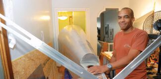
At long last, on Memorial Day 2005, the wings and fuselage met for the first time. We set the wing on the tires and let it rest on Kruegers piano bench. With the airplane taking up most of his living room, there wasn’t much piano playing going on anyway. Then we lifted the fuselage, complete with nosegear, over the top of the wing and set it down.
At first, there were a couple of small interferences that blocked the marriage, but 5 minutes with a file solved them. There are four places that must line up between wing and fuselage, the most important being just above the mainspar, where two tangs of 0.063 aluminum bar stick up from the wing and slide between three similar tangs on the fuselage side. At the rear spar, there’s a similar one-into-two arrangement. Then there are about 20 nutplates that must match on the rear floors and tunnel.
There is a lot of friction in this arrangement, so it took some judiciously applied muscle to slide everything into place. But when we had tapped everything home, we were excited to find that every single hole lined up. The flaps and ailerons, pushrods, control column and flap lever were already installed in the wing, so within a few minutes we could toss a couch cushion into the cockpit, sit down and make airplane noises while wiggling the control surfaces.
The biggest surprise, however, was how big the project was. You can look at a computer screen all you like, but when the reality is sitting in the living room it is a different story. We could not get over how much larger it seemed in real life. The cockpit was huge, probably the roomiest either of us had ever seen on a single-seat airplane. The fuselage sat tall on the tricycle gear-really tall. Even for guys our size, it was a big step up onto the wing. I realized that our 450-pound empty weight wasn’t going to happen…thats less than half what the RV-6 weighs. I knew Krueger was good, but I didn’t see how anybody could design an airplane 85% as big as an RV and make it weigh less than half as much! In the back of my mind, something said: 500 pounds, buddy.
At long last, it really looked like an airplane, even if it was trapped between a piano and a French door! Next month well wrap this up with final assembly at the airport, test flying and performance measurement.

