Inside aviation spark plugs is a carbon resistor. Its purpose is to reduce excessive spark current, which contributes to electrode erosion and shortens the life of the plug.
When a spark plug is put into service, its resistance value slowly begins to increase. High internal resistance can make an engine misfire, run roughly, or be difficult to start. It can also cause poor combustion and increased exhaust emissions.
When spark plugs are new, the resistance value is between 500 and 3000 ohms. As the plug ages, values below 5000 ohms are acceptable. But once the plug’s resistance value exceeds 5000 ohms, the plug should be replaced.
If a spark plug falls off a workbench or is dropped, it’s possible for the carbon resistor to break. If this happens, the resistance value will probably exceed 5000 ohms, and the plug will need to be replaced.
A quick way to measure spark plug internal resistance is with a resistance tester. Commercial units are available, but I decided to build my own.
Required Parts
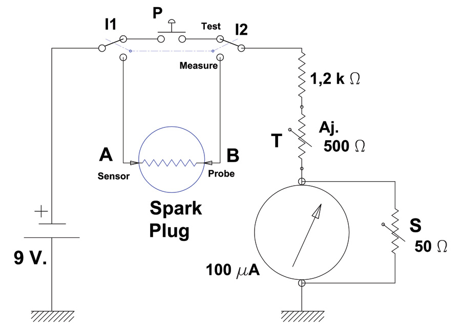
The test stand is in fact an ohmmeter. Components shown in the schematic include:
- 9-volt battery
- 100-A microammeter shunted by a 50-Ω potentiometer (S)
- Double-pole rocker switch (I1, I2)
- Pushbutton switch (P)
- 500-Ω variable resistor (potentiometer) (T)
- 1, 2 k-Ω serial resistor
- Brass sensor (A)
- Probe with 1-foot wire (B)
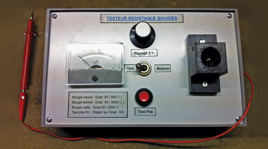
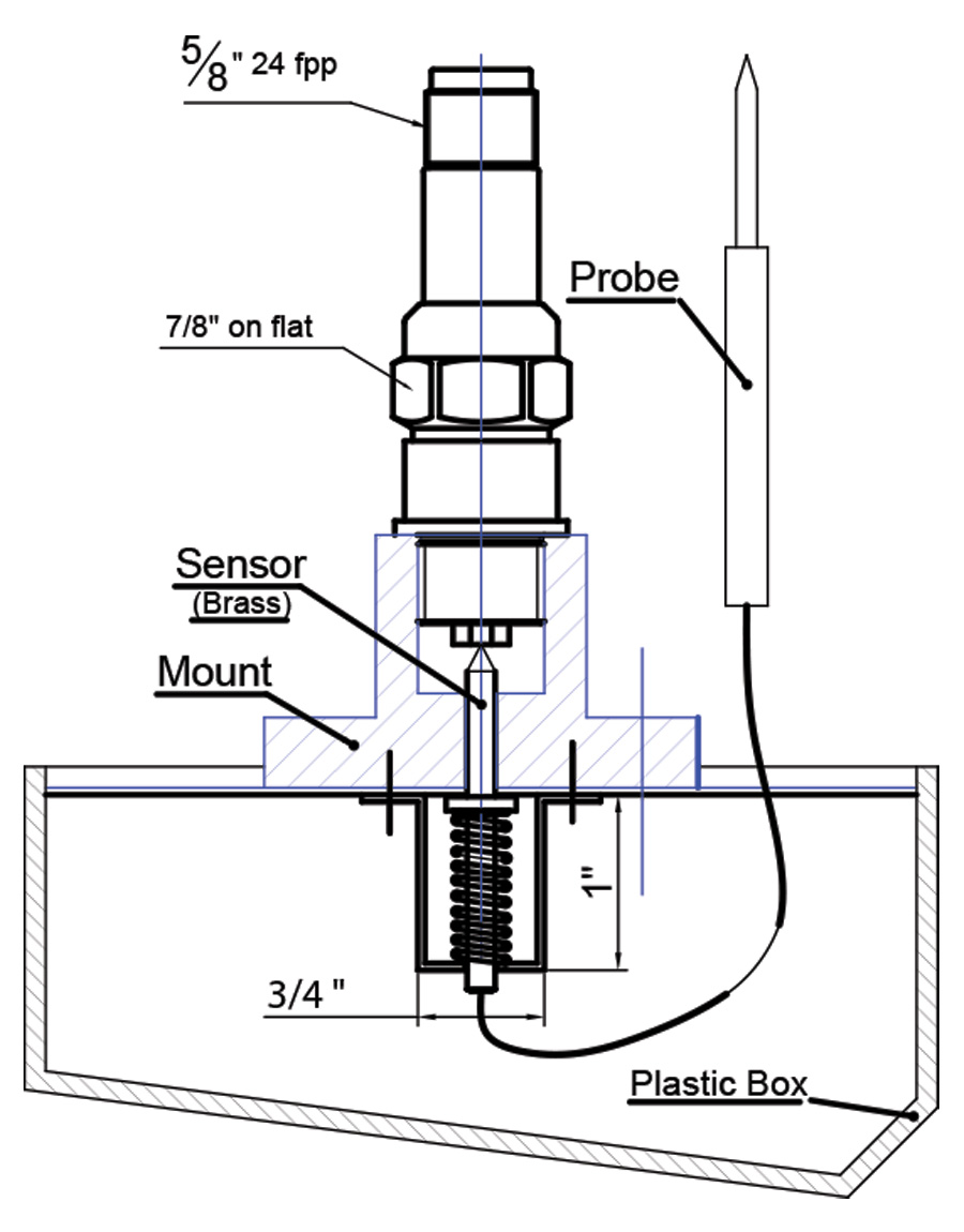
All of the parts will fit in a plastic box measuring 8.5 x 5.125 x 2.5 inches. I made a plastic mount to hold the spark plug upright during testing. The mount is attached to the top of the box, and a spring pushes the brass sensor against the electrode.
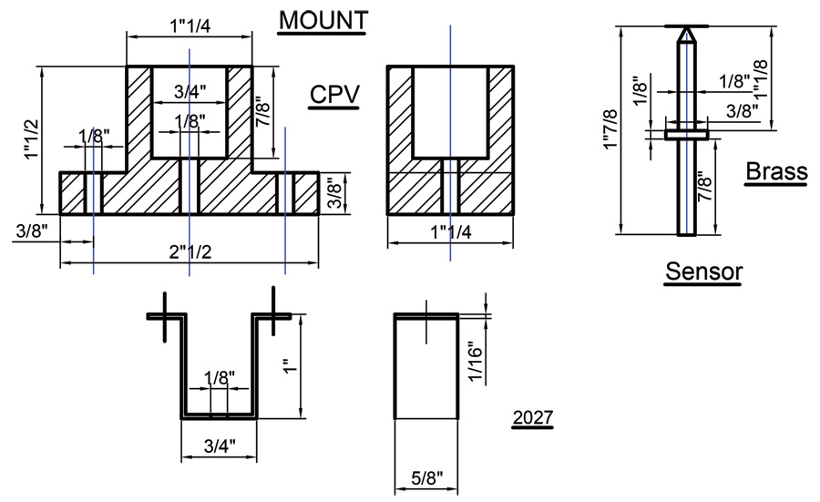
The spark plug mount was made from a block of plastic. Dimensions are shown for the mount and the brass sensor.
Pre-Test Setup
First adjust the 500-Ω potentiometer (T) for full resistance. Then set the rocker switch (I) to “Test.” Push the button (P) and adjust the 50-Ω potentiometer (S) until the microammeter shows 100 A. I found S = 17 Ω on my prototype tester, with a 1.2 kΩ serial resistance.
Test Procedure
1. In order to check battery wear, first adjust the control voltage. Put the rocker switch in “Test” position and while holding down the pushbutton (P), adjust the 500-Ω potentiometer (T) until the microammeter indicates 100.
2. Set the rocker switch (I) to “Measure” and put the spark plug in the mount. The central electrode should be touching the spring-loaded brass sensor (A).
3. Push the spark plug down to ensure good contact against the sensor, then insert the probe (B) into the barrel of the spark plug. The probe must touch the contact, which is connected to the spark plug’s carbon resistor.
Important! Before the test, it is imperative to carefully clean the central electrode with a brush. This will help avoid contact resistance, which could distort the results.
4. According to spark plug manufacturer Tempest, you should see the following values on the microammeter:
New spark plug: 80 (500 Ω)
Good spark plug: 40 (3000 Ω)
Used spark plug: 25 (5000 Ω)
9V Battery Test: 100
Due to the shunt (S), the values shown on the microammeter are not actual A values. They must be referenced to the values shown above to determine spark plug resistance.
Note: It’s possible to check the test results by inserting a resistor in place of the spark plug, with a value equivalent to the needle deviation (e.g., with my prototype tester, a 500 Ω resistance corresponds to 80).






Michel,
New NGK Iridium’s state 5k ohm
And double Iridium Bosch at 6k ohm.
How do these measurements compare to your measurements?
Thanks,
Mark in GA
What exactly is the long rectangle object next to the 9 volt batter and just on top of the Meter, in the picture it has small black and red wires going to the 9 volt battery on one end and two large red wires on the side or edge going to the Meter?
That’s the 500-Ω variable resistor (potentiometer) (T). Specifically this type:
https://www.bourns.com/pdfs/271_273_275_obsolete.pdf
I find that it’s much simpler to use a digital multimeter on the 10k or 20k scale, depending on the meter. Some auto range so the reading with take a few seconds as the meter changes range.
One probe goes inside the spark plug, where the plug wire goes. Be sure that the probe is contacting the center contact.and the other to the center tip. You will have to ‘scratch’ the plug tip to remove any combustion products to get a good connection.
A good Tempest plug will be in the range of 1k, [ 1,000 ohms], to 2k ohms.