The terms drilling and boring are often interchanged, but in the context of metalworking, they are not the same. Drilling is how we create a hole, and boring is how we enlarge and true an existing hole.
In previous columns I have shown various boring operations on the lathe [“Home Shop Machinist,” September 2014, November 2014, and August 2015]. This month we’ll look at boring on the vertical milling machine and two common ways to bore precision holes.
End Mill Boring
Boring a small hole (up to -inch) is greatly simplified if the design calls for a standard-size end mill diameter. End mills are more rigid than drill bits and more precise. An end mill in a collet or tool holder has very little run-out compared to a drill bit in a Jacobs chuck. This makes them an excellent choice for precise bores.
To make a 1/4-inch bored hole, for example, start by drilling a clearance hole that is slightly undersized, such as with a 3/16- or 7/32-inch twist drill. Then, swap out the drill chuck for an end mill to make the final size. You will probably have to raise or lower the knee (or raise the head if you have a mini mill) to facilitate the tool change. While any Z-axis movement will not alter the alignment for final boring, it’s a good practice to use the table locks to prevent inadvertent X- or Y-axis movements. If for some reason you have to make an X or Y move, simply zero the dials on the handles before you traverse the table. That way you can “zero in” to the original location after the tool change. If you get lost, or don’t trust your repositioning accuracy, an edge finder can be used to re-establish the center of the hole.
Pre-drilling a clearance hole, then plunging with an end mill is a fast and easy way to precision bore a hole—as long as the size matches something in your end mill collection.
It’s possible to use a center-cutting end mill without drilling a clearance hole. But it will not be as accurate or have as nice a finish. With a clearance hole, the end mill is removing very little material. A lighter cut makes for a smoother finish. It also generates less heat, which results in a more accurate bore.
For most home shops, the drill and end mill method will be practical up to -inch, simply because -inch will be the largest diameter end mill in the collection. To make larger bores, or bores other than end mill sizes, an adjustable boring head is the ticket.
Using a Boring Head
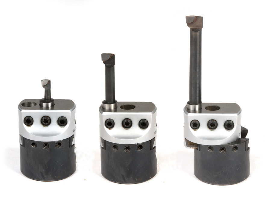
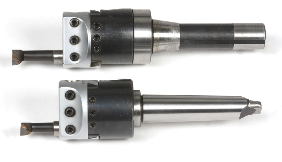
Boring heads come in many sizes, from micro to behemoth. A good size for the home shop is a two-inch boring head like the ones in the photos. Look to pay around $100 to $130 for an import set that includes a small assortment of boring bars and the appropriate shank or taper for your machine (usually R8 for most knee mills or MT3 for the mini mill). I purchased mine at LittleMachineShop.com, but similar sets are available from Enco, KB Tools, and Amazon.
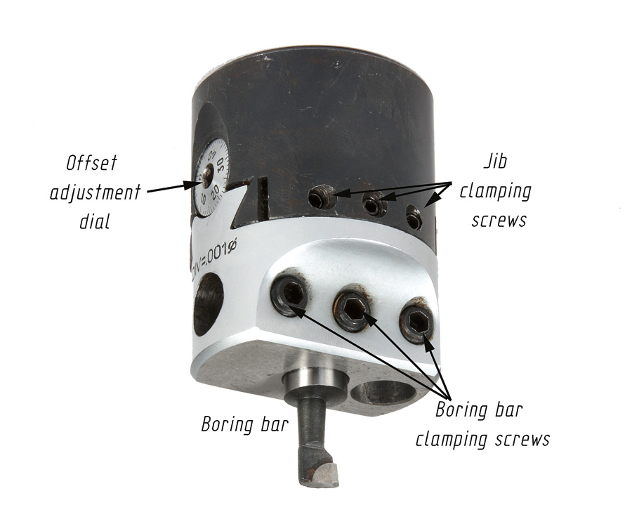
At first glance, the boring head might appear a little intimidating. It’s actually quite basic: There’s one or more sockets to clamp the boring bar, jib-clamping screws, and an adjusting dial.
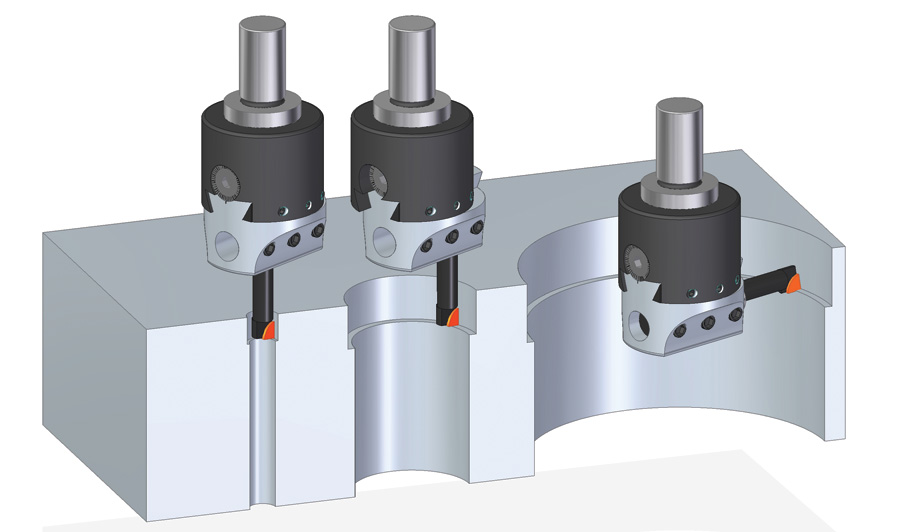
My two-inch boring head has three tool positions: The center-vertical position is used for small holes, 5/16 inch being the minimum (depending on the boring bar used) and adjustable up to about 1 inch. The outside-vertical position is for holes from about 11/8 to about 23/8 inches (again, depending on the boring bar used). The horizontal tool position can make bores from 21/2 inches up to whatever length boring bar you have, or whatever you have the guts to try! Keep in mind that each setup will have its own practical limit for rpm, balance, and tool chatter. Note that some boring heads, especially smaller ones, may have only one tool position, but they all have some method, typically a graduated dial with a hex key socket, to adjust the slide offset.
To bore a 0.860-inch hole for the example, I started with a -inch clearance hole. Since the minimum size for my boring head is 5/16-inch diameter, starting with -inch gave ample room for the tool to go in the hole without touching. I then adjusted the slide until the cutter tip just touched the inside of the hole and noted the dial reading. The dial is graduated in 0.002-inch increments. Each full turn of the dial moves the slide 0.050 inch. Since we’re working with diameters, for every x of slide movement (or depth of cut), we get 2x change in diameter. Therefore, to enlarge my -inch clearance hole to 0.860 inch, I need a slide movement of about 0.180 inch (0.180 x 2 = 0.360).
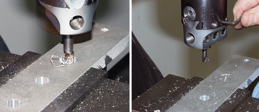
Using the boring head to make small, medium, or large bores. Note when using the horizontal position, you need to use a “left-hand” boring bar.
I say “about” because I like to make a light first cut, check the result, and adjust accordingly. In this case I set the slide to remove 0.030 inch. The cutting went very smoothly and resulted in a cleanly machined hole that measured 0.569 inch. This told me the touch-off point in the clearance hole was 0.509 inches. With the new dimension noted, I did two passes removing 0.070 inch (0.070 on the dial = 0.140 diameter increase) and measured to confirm. This left me with a 0.005-inch final pass to “clean up” the bore and hit the target dimension. Upon inspection with my bore gauge, the hole was 0.861 inch. All in all, this was an excellent result considering I didn’t use anything fancier than my 8-inch caliper to check the bore between passes.
The goal of boring is to achieve an accurate size with a smooth finish. If the first pass or test cut results in chatter, then the depth of cut, spindle rpm, and choice of boring bar may be contributing factors. The example part was 7075 aluminum and the spindle rpm was set at 900. For steel I would have set the rpm to 500, and possibly reduced the depth of cut to around 0.020 inch.
Opening the -inch pilot hole with a 0.030-inch initial cut (left). Tightening the jib clamping screws after adjusting the offset (right).
The spindle rpm and feed rate depend on the material, the size of hole you are making, and how much the slide is offset. If you end up with a lot of slide offset, the boring head will be out-of-balance and can cause the machine to vibrate. Your only choice is to lower the rpm until the vibration is eliminated or, at least, minimized. As you lower the rpm, the feed rate needs to be slower as well to maintain a smooth finish.
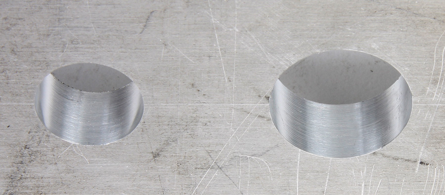
The hole on the left was bored using an end mill and the one on the right using the boring head. Both are good examples of a cleanly machined surface made by boring.
Final Thoughts
Boring can be a slow and tedious process (no pun intended). To get good results, you have to be patient and meticulous. Making a series of light passes will give you better results than pushing large, heavy cuts.
Note also that to maintain a good finish, you must feed the cutter back out of the hole at the same rate that you feed it in. There is always some deflection in the boring bar, so the feed-out pass is what actually determines the size of the bore.
You should measure the bore after each pass to confirm that your adjustments correspond with the expected or target dimension.
Every time you move the slide to set a new depth of cut, you must retighten the jib clamping screws that secure the slide.
The offset adjustment is finite: about one-third of the head diameter is as far as you can go and safely clamp the head.
It’s possible to open a -inch hole to a 3-inch hole with our 2-inch boring head. You start in the middle socket, move the bar to the outside socket, then install a bar in the horizontal socket. Cut, then measure, and so on, until you land on the desired dimension.
Be patient!

