Late in the fall of 2013, Texas-based Solid Concepts made headlines when it released a video demonstrating a fully functional semi-automatic pistol assembled from parts produced entirely by additive manufacturing methods.
Additive manufacturing, more commonly referred to as 3D printing, has been around for a few years, but the process is getting a lot of press lately. This is mostly due to firearm projects like the Solid Concepts gun or the infamous Liberator “plastic Internet” gun. In either case, the reporting is accurate on at least one relevant fact: it is possible to make functional parts on a 3D printer. Consumer 3D printers such as MakerBot or Cube sell for between $1,000 and $3,000. This makes them appealing to the tinkering class (of which homebuilders definitely belong). Consumer-grade 3D printers have limitations, but they can be practical for vetting designs, as well as making non-structural items such as interior trim, panel widgets, and other gadgets. As far as making structural metal parts, that equipment is not for the tinkering class because they cost $600,000 or more. While this puts them out of reach for homebuilding, you don’t need to own one as you can have parts made by any number of service companies like Solid Concepts.
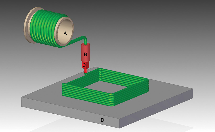
3D printing basics: A) Spool of material, typically ABS or polyethylene; B) Heating element to melt the plastic; C) Nozzle; D) Platen. Depending on the make and model of the printer, the platen might move CNC-style in X, Y, and Z motions to resolve the shape, or the spool, heater, and nozzle could be mounted on a moving gantry to facilitate the depositing process.
How they work
Typically, 3D printed parts are made by depositing and fusing thin layers of material, one on top of the other. Think of it like squeezing toothpaste out of a tube in successive parallel lines to make, let’s say, a square. Then keep adding layers on top of each previous one until you have a cube. Now imagine adding only around the perimeter: you’ve made a box. Virtually any physical shape can be created using this technique. Add material where there’s solid space and leave the negative space blank.
Consumer 3D printing machines work like the toothpaste example: a spool of plastic thread is fed into a heating element, melted, and then deposited via a nozzle onto a table or platen. The feed system, heater, and nozzle are typically mounted on a gantry that is stepped in small X (left and right), Y (front and back), and Z (up and down) increments. A built-in controller slices up the design (a CAD file) into the required layers and tells the machine where to move and when to deposit material.
Another type of 3D printing, called stereolithography (SLA), creates layers by shooting an ultraviolet laser beam into a liquid bath of photosensitive resin. Wherever the laser is focused, it instantly cures the resin to solid. Mirrors aim the laser, which rapidly scans back and forth to form the fused layer. The platen is then lowered to submerge the just finished layer, and the process repeats. Each new layer is fused to the previous layer. Once the part is done, the excess resin is washed away, and it’s finish-cured in a UV chamber. Stereolithography can make amazingly accurate parts out of a variety of plastic materials, but machines are expensive and generally not practical for small shop or consumer use. If you need a critical one-off that requires stereolithography you can job it out to any number of “on demand” 3D printing companies.
A third style of 3D printing builds up layers by sintering (solidifying) powder-based materials. When the powder is plastic, the process is called selective laser sintering (SLS). When the powder is a metal alloy, the process is called direct metal laser sintering (DMLS). Either way a laser is used to melt the powder and fuse it to the previous layer and/or an adjacent face. The powderized material is spread on a platen and the laser “zaps” the selected areas to create a layer. The resolution and accuracy of laser-sintered components rival any traditional manufacturing process. Each layer can be as thin as 20 microns (about 0.0008 inch), which means they are mostly invisible. Metal parts made this way are not any different than any other: they can be polished, reworked, or processed the same as any other billet, cast, or forged part. Plastic parts made using the SLS process are similarly precise and can be structurally comparable to injection molded parts. (For more information on DMLS, hike your browser on over to the Solid Concepts web site: www.solidconcepts.com).
A subcategory of the sintering style was developed at MIT and is currently being marketed as a “ZPrinter.” The ZPrinter uses a talc-like gypsum powder somewhat akin to plaster of Paris. An inkjet printhead zigzags above the powder, wetting the mapped area to create a plaster-like layer. The platen is lowered and a fresh layer of powder is spread over the surface, and the process repeats over and over until the part is complete. To finish the part you spritz it with cyanoacrylate (CA) glue, which solidifies it into a pseudo-ceramic mass that can be sanded, carved, and painted. While this type of powder-based printing can directly produce casting patterns, or, with a special binder, flexible parts that act like springs or rubberized components, dimensionally the parts are not very accurate and they’re fragile. The main attraction of the ZPrinter is for making cosmetic facsimiles. It’s not a technology that can directly produce structural parts or replacements for plastic parts.
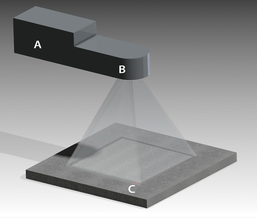
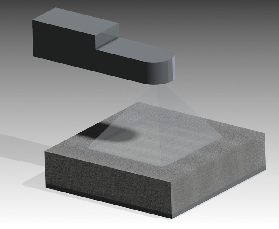
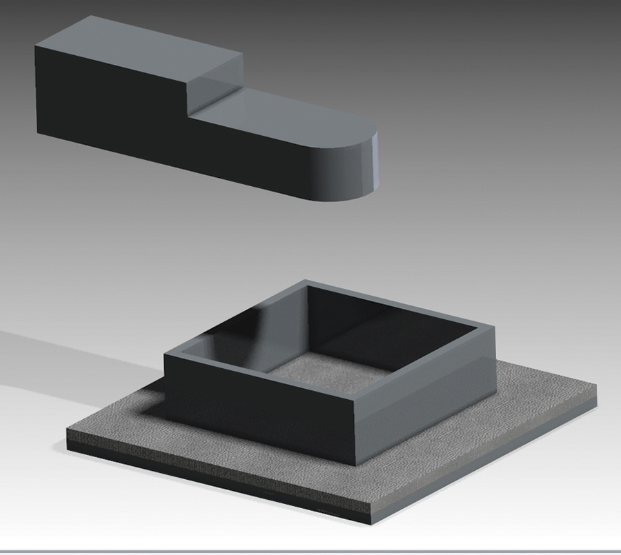
This sequence illustrates the general principal behind Selective Laser Sintering (SLS) and Direct Metal Laser Sintering (DMLS). A thin layer of powdered material is spread over a platen. Left: The laser (A) shoots through a focusing mirror (B) which is controlled by a computer to rapidly scan the pattern and fuse the material (C). Middle: Successive layers are built up until; Right: the desired part is finished.
3D Examples
I kicked around several ideas for a demonstration part that would have good general appeal to KITPLANES® readers. A key objective was it needed to be something that favored 3D printing over traditional (subtractive) machining. Example: you could make a flanged bushing with a 3D printer, but why bother? It’s only a five minute job on the lathe.
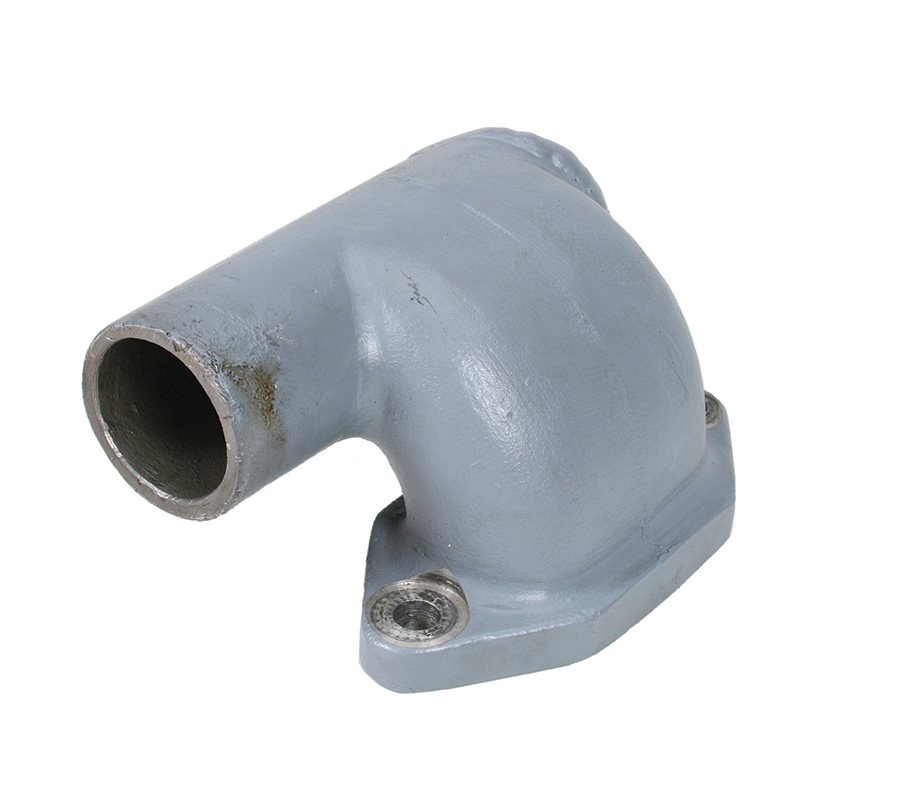
I settled on making a set of intake manifolds for my Great Plains 1915cc engine. Actually, I have two engines and the original Great Plains manifold set is presently residing on my installed engine (a Mosler VW conversion). The old manifolds interfere with the spark plug caps, which is not a big deal, except I like to run the engine every once in awhile to circulate the oil and exercise the innards. So, a new set of manifolds were in the offing anyway.
The manifold is a good project for 3D printing. It has sweeping curves and deep cavities that would be a challenge for CNC machining. Production manifolds like this are sand cast, and for good reason: casting is a great way to make small-lot production runs of complex shapes. But sand casting is not so practical for prototypes or one-offs.

A computer model of the (hopefully) improved design. A low-cost plastic prototype will be used to “proof” the fit and compatibility with the engine and spark plug wires.
I could try to make an exact replica of the Great Plains manifold, but why not “improve” it. I’m not an intake manifold designer, so I consulted VW engine guru Donny Karraker. The only improvement he suggested was to add some rise to the inlet stack to eliminate the manifold spacer. I added a little more than a half inch and also made the curves slightly tighter so the split for the two ports can be more upstream. After some basic 3D design work in Solid Edge, I had the foundation for the next (part two) segment of this article: printing a plastic sample to test the fit and then finalize the design and create functioning parts. I can’t wait!
Special thanks to Chuck Alexander, Product Manager Additive Manufacturing, Solid Concepts Inc.
Photos: Lori Fahrenholtz

![]()
Bob Hadley is the R&D manager for a California-based consumer products company. He holds a Sport Pilot certificate and owns the VW-powered Victory Stanley Fun-Kist.




Bob,
Any thoughts on how one would get dimensions of an object into Solid Edge? I made a fairing for my plane out of foam and fiberglass – but, would like to try 3D printing a copy of it so I can refine it a bit more. The challenge I have is how do I get the shape of my prototype into Solid Works so I can tweak the design (add things like recessed screw holes, etc.).
Craig
I’ve used my 3d printer quite a lot during my build of my Zenith 750 STOL. mostly made templets and jigs. But also made parts that turned my vice grips into fluting pliers and seamers. Used the Dynon models to lay out my panel. Made a mount for my android. A knob for my parking brake. Molds for fiberglass work.