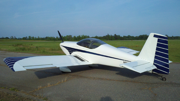
This story began last month, as I described the unhappy mating of my RV-9 and a grounds keeping cart that, from all outer appearances, took out the propeller and the lower cowling. As you now know, this collision did much more than that, smashing accessories and forcing an engine teardown.
Technically, the repair of N941WR isn’t a rebuild but an engine swap. With no damaged sheet metal and all of the carnage limited to nonstructural items (aside from the engine mount), you might think that all of the work consisted of removing the old engine and bolting on a new one. Simple work for someone who built the aircraft in question, right? Wrong!
There’s yet another layer to consider, too. As we discussed last month, the Lycoming O-290-D2 engine originally installed is now rare enough that an easy replacement or rebuild wasn’t in the cards. As such, not just a new engine but a new model of engine would be installed. And each new variable introduced several others.
Even for the most dedicated and successful builders, life has a way of getting in the way of the project at hand. The birth of a child prior to the taxi incident limited the amount of time available to work on the plane. When choosing between spending time working on the plane or spending time with my wife and child, I will pick the family every time. Thus, the work required to put N941WR back in the air, while not difficult, was more limited time wise than it was during the original build.
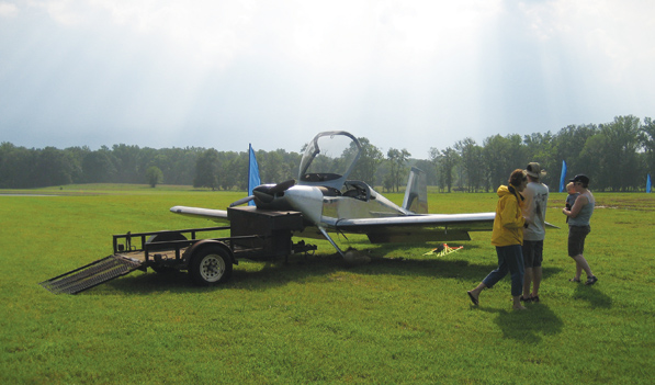
This is where the fun began. The author was ambushed by an unattended and unseen landscape trailer.
Where to Begin?
All builders, working on their first project or fifth, must contemplate where to begin. It is no different when you are repairing a damaged aircraft.
The list of replacement parts helped define the order in which the work should be completed. So the natural order emerged: Remove the damaged components; remove the engine; inspect everything; and then begin ordering replacement parts. Naturally, the new items don’t all arrive at the same time, so an intermediate step is to work on pieces and subsystems whose components arrived early.
Following in rough order: Build the engine kit; hang the engine; install all of the supporting systems; and then fit the new cowling. Easy!
Uh, Not So Much
First things first. The basement workshop had to be readied for the return of the RV-9. This included building another stand to hold the fuselage in preparation for the removal of the gear legs. (The original stand was given to a friend who was working on an RV of his own.) With the O-290-D2 removed and set aside, the gear legs were removed, the fuselage lowered onto the stand, and the old engine mount unbolted.
Most of the replacement parts were ordered from Van’s Aircraft. The staff at Van’s was extremely helpful in providing the correct part numbers, reviewing my list and suggesting how to reduce the cost of parts by purchasing subkits rather than individual items. In addition, they expedited the order, as these parts were destined for a “flying” aircraft.
While waiting for the Engine Components, Inc. (ECi) engine kit and a large box from Van’s to arrive, the time was right to remove the accessories from the old engine and send them off for inspection. The dual P-Mag electronic ignition units were removed and returned to E-Mag Ignitions, where they were disassembled, inspected, reassembled, bench tested and returned for a nominal fee. No damage was noted, so they will fly on N941WR once again. The 122-tooth Sky-Tec flyweight starter was removed and exchanged for the 149-tooth starter required for the larger engine. A new alternator was ordered from Plane-Power to replace the original, which was damaged when the aircraft hit the trailer.
Closed for Inventory
If you get the impression that a good amount of time was spent inventorying damaged parts and ordering replacements, you are correct. When building a kit aircraft such as an RV, parts selection is an easy process; you simply call Van’s and order the next subkit. When rebuilding an aircraft, you have to order the parts individually, and identifying the required parts can be time-consuming.
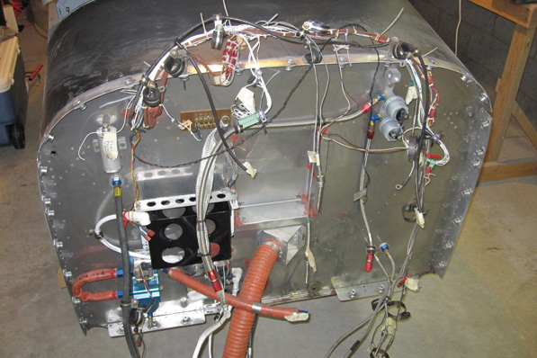
With the engine mount removed, it was a good time to clean and inspect everything.
While removing the engine would normally be an easy process, additional time was taken to tag each wire and the location of each Adel clamp on the old mount. Photographs help this process as well. The idea was to make the installation of the new engine as easy as possible-no need to reinvent something that was working before.
Installing the replacement engine mount proved to be a challenge. Inserting the upper left bolt first and working clockwise, each bolt was installed until the final lower left bolt. That last bolt did not fit, and no amount of persuasion would convince it to slide into place. After much discussion with Van’s, the vendor who made the mount and some more experienced builders, I returned the new mount to Van’s. It was measured, checked, rechecked and returned to me. The mount was the correct size, and all of the holes were properly located. I was stumped as to why the new mount did not bolt right up. After all, the original mount was used as the drilling guide for all six holes when the aircraft was built.
After further consultation, I decided to try again. This time, the bolts were installed in a cross pattern, similar to how you might torque the bolts on a propeller. No struggling, no large hammer required, no fuss, no re-drilling the holes; all of the bolts were installed and torqued in a matter of minutes. Lesson learned. With the mount in place, the gear legs were installed after the wheel bearings were repacked, and new tubes and tires were installed. (The rebuild was a good time to perform the annual condition inspection and tend to wear items such as tires and brakes.)
Where’s My Engine?
Before the engine mount was truly required, we needed an engine. The ECi O-360 kit arrived a month after the engine mount was installed. Two friends volunteered to help me assemble it, a process I didn’t want to tackle on my own. One of the Gang of Three is an A&P who helped another gang member assemble his ECi O-360. As the third gang member, my job was to bring steaks and diet soda, and the engine kit, of course.
The work was completed at the A&P’s shop. Prior to the engine leaving my home, I honed the valve seats and assembled the cylinders. That is a fairly easy task and one I knew I could accomplish on my own-the ECi kit is just that, so there were many small subassemblies to build before the engine took shape. My wonderful wife was on hand to help compress the valve springs and install the valve guides, so once again, I have to give credit where credit is due. Thank you, Mr. Turner, for raising your daughter with a wrench in her hand.
It took the three of us two full days to assemble the engine, eat some steaks, tell flying stories, and finally load the completed engine into the back of my pickup for the trip home. One of the key things that most builders take for granted is organization. Before starting, gang member No. 1 wouldn’t let us begin assembling anything until we got organized. One of the items he insisted I bring was a roll of butcher’s paper, and after laying that down on our work surface and organizing the parts in order of installation, I understood his logic. The paper helps prevent the parts from getting contaminated with dirt from the workbench and makes each part easy to spot on the clean surface.

The ECi engine kit is being organized prior to assembly. Note the butcher paper protecting the parts from contamination.
Assembling an aircraft engine isn’t particularly difficult, but the mixture of lubricants and sealants is key to building a leak-proof and strong engine. Although I have assembled engines before, it was comforting to get guidance from an experienced A&P. At the end, I had great confidence in this engine, and I was sure it had been assembled correctly with the proper parts.
Hanging Party
Builders dread the thought of installing their engines. The old O-290 had conical mounts that took just a few minutes to bolt in place. The new ECi engine was a different animal altogether. I have read horror stories about installing engines with Dynafocal mounts, and this is where my favorite Internet search engine came in handy. (For those of you unfamiliar, the Dynafocal mount uses four large rubber “doughnuts” with large bolts down the middle. The bolts are angled differently for each mount, with the idea being that the extended line of each long axis meets somewhere near the engine’s center of gravity. In theory, this creates a mount that is more effective in isolating vibration, but it also complicates wrestling the engine into place.)
Located on Doug Reeves’ Van’s Air Force web site is “An Illustrated Guide to Engine Hanging” by the Tampa RV Builder’s Group: Jim Norman, Scott Reviere, Don Hughes, Doug Gardner and James Samonsky. What a great document! With these instructions in hand, I descended into the dungeon known as Bill’s Aircraft Factory to do battle with those dreaded Dynafocal Type 1 engine mounts.
Forty-five minutes later, I was running upstairs in a failed attempt to locate my camera. The instructions are clear and concise, and they allowed me to install the engine single-handed without so much as scratching the engine mount. Amazing what a little education can do.
Glass Half Full
With the engine hung it was time to fit the new cowl, in this case a non-stock, James Aircraft Holy Cowl. Why go partway with these changes? Why not add a few more variables to make it really interesting?
Installing the cowl during the original build was fairly straightforward, but matching a new cowl to the existing fastener holes would prove to be a challenge. Or so I thought. Trimming the top cowl first, as is the practice, was simple. With the spinner installed, a piece of scrap aluminum angle was used to set the gap between the cowl and the spinner. Two rolls of paper towels nestled between the cylinders helped hold the top cowl at the proper elevation, and a trouble light was placed inside the engine compartment so the edge of the firewall could be seen through the translucent fiberglass. Black electrical tape was used to mark the cut line on the cowl. Trimming the cowl and sanding the edge straight with a long board was a non-event.
The original cowl was held in place with quick-turn fasteners, which have large holes on the mounting flange. To make sure the new cowl lined up perfectly, I made a small aluminum plug with a #40 hole in the center. The plug was placed in the fastener’s hole, and a hole-duplicator was used to drill a matching hole in the new cowl. The cowl was then removed, the #40 hole was enlarged and the quick turn fastener was installed prior to moving to the next hole. As with the original cowl, I started with the center hole and moved to the outside, alternating between the left and right sides. While a time-consuming process, the new cowl fits as well as the original.

The quick-release fasteners are in place, sequenced so that the valve covers will not hit them when the engine rocks.
Oops
The Holy Cowl does not come pre-cut with a location for the oil filler access door. After identifying where I wanted to place the oil door, I covered the top cowl with stretch wrap and laid five layers of fiberglass over the pre-marked door. I wish that were the end of the story, but in my rush to finish something, anything, I over trimmed the door after I cut the hole in the cowl. A quick call to Will at James Aircraft had another layup headed my way.

Fitting the bottom cowl. The bottom cowl part line has been trimmed, and the part line is scribed on the blue tape affixed to the top cowl, which still needs to be trimmed.
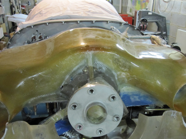
A cooling plenum performs an outstanding job of keeping the cylinder-head temps in check, but it must be modified to provide a tight fit.
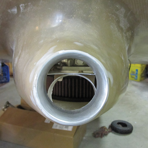
Something doesn’t look right. The stock filtered airbox (FAB) does not line up with the air inlet on the bottom of the cowl.
The inside of the bottom cowl was sealed to prevent it from absorbing oil with four coats of epoxy and acetone mixed 50/50 and rolled on with a 3-inch high-nap paint roller. After this layer hardened, the inside of the lower cowl was covered with a sheet of self-adhesive heat shield, which is similar to contact paper. To smooth out the heat shield, a wallpaper seam roller was employed. The edges of the heat shield were taped off, and a skim coat of clear RTV was used to seal the edges and prevent the heat shield from peeling up. (The tape was removed immediately following the application of the RTV.)
Unlike the standard item, the Holy Cowl is designed to work with a cooling plenum. The plenum provided is a close fit, but some additional trimming and fiberglass work was required. For my installation, I cut the front of the plenum off, covered the engine in Vaseline (otherwise known as the poor man’s mold release) and glassed the plenum directly to the engine and inlet ramps. While I was at it, I built a ramp at the aft left of the plenum to provide more air to the oil cooler mounted behind the No. 4 cylinder. Overall, the substitution of the Holy Cowl added little in the way of extra work, with the notable exception of the plenum.

Here is the FAB at the beginning of the modification process. Have hacksaw (plus styrofoam and fiberglass), can modify.
There is something to be aware of, however. James Aircraft makes two versions of this cowling, one short and one long. The short one-and I’m referring to the length from the firewall flange to the prop cutout here-is sized similarly to the stock Van’s cowling. If you’re changing from a short to a long cowl, say, because you want to also change to a front-facing induction system, you’ll need a different prop extension.
I elected to use the standard 2.5-inch prop extension, which mandated the short cowl. Most short-cowl customers run fuel injection, and as luck would have it, the carburetor introduced another level of complexity, which required rebuilding the filtered air box (FAB). The modified FAB required a custom designed and manufactured carb heat flapper and installation. Most people I consulted suggested a swap to injection to make installing the new cowl easier. But being somewhat stubborn by nature, I was not ready to give up.

| The FAB plug trimmed from a sheet of styrofoam. | Marking the styrofoam with the cowl installed. | The styrofoam mold scribed for the cowl air inlet. |

| The styrofoam plug in the trimmed FAB, prior to fiberglassing. | Test fitting the modified FAB and carb-heat valve. | The completed filtered air box and carb-heat-valve installation. |
Scratch That Itch
Having come to terms with working with fiberglass, I once again descended to my basement workshop, located my hacksaw and started cutting. First, I started working the stock air box only to realize that it was not even close to lining up with the cowl’s intake. The solution came to me in the form of a product from my hometown: blue Dow styrofoam. After cutting the front of the stock FAB off, I formed some styrofoam into the shape of a slingshot. This was placed in the FAB, which was installed on the carb, and then the bottom cowl was mounted. With the foam butted up against the cowl’s air inlet, I simply traced the inlet onto the end of the foam.
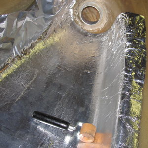
A wallpaper seam roller does an outstanding job of pressing the heat shield into the contours of the lower cowl.
With the mold made for the FAB, the next challenge was to make a flange for the carb-heat hose. After talking to an Inspection Authorization (IA) friend who had commented on how often he has to rebuild carb-heat boxes, I elected to make the carb-heat valve and flange removable to facilitate maintenance. The final installation has worked out well and provides significant rpm drop during the runup, and a noticeable increase in carb temp in flight.
Wrapping It Up
With the reconfiguration of the carb-heat system complete, the rest of the rebuild was uncomplicated. The upper intersection fairings had to be fabricated because the new cowl was not exactly the same as the original (forming the gear fairings). To keep my wife happy, a custom leather interior was purchased from Classic Aero Designs to replace the original painted aluminum interior. The interior paint was touched up, and the plane was given a complete airworthiness inspection while it was disassembled.
Prior to the taxi incident, N941WR was scheduled to go to the paint shop. Obviously, with the taxi incident that was delayed, and the airplane now sports a new paint job to complement its new engine and cowl. Next month, we’ll wrap this up with my impressions of the flying qualities and performance of this RV-9 with a sleek new cowling and a bunch more power under it.
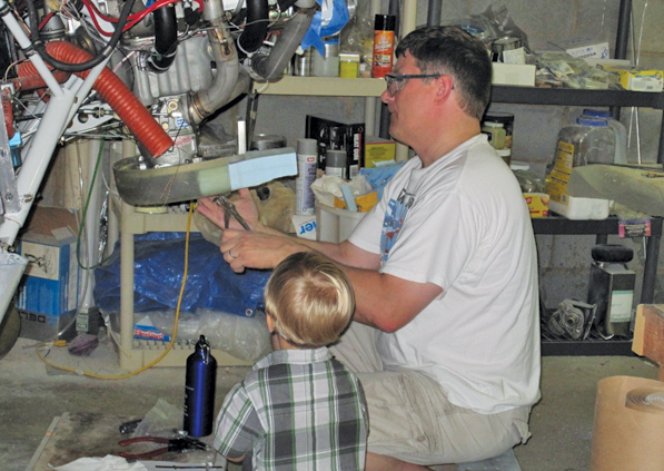
Daddy, when are we going to go flying again?


