Four years ago I was at the stage of fitting the engine cowl to my Van’s RV-7A project. The engine and prop were in place so that the cowl could be accurately aligned to the spinner. My project is a nosewheel “A” model and uses the horizontal induction cowl, affectionately known as the slick cowl. The cowl supplied with the kit is configured as an upper half and a lower half. It was easy to work with the upper cowl half, but fitting the lower half was difficult because the nosegear slopes forward, pushing the cowl into the back of the spinner as the cowl is lowered. This creates the need for a long slot in the lower cowl, which is typically covered by a separate gear leg intersection fairing/cover piece. Placing and attaching the lower cowl when working alone was quite a challenge, and I dreaded repeating the operation after the parts were painted. One post on a popular online forum showed a special wheeled cart that a builder created just so he could install and remove the lower cowl on his nosewheel RV without needing an assistant. I didn’t like the sound of the problems related to installing and removing the lower cowl.
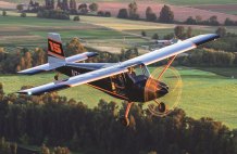
Strategically, a week at AirVenture gave me a chance to chat with a famous airshow pilot, and over his shoulder I noticed that the right half of his engine cowl was removed. It immediately looked like the solution that I needed. Later, while touring the grounds, I observed that most Sonex aircraft cowls are split vertically, rather than horizontally like the RV cowls. I took several photos and started sketching possible vertical-split cowl solutions for an RV-7A.

The plane that sparked the idea. The author noted that the vertical-split cowl on this famous airplane might be a better solution for his RV-7A cowl problem.
Vertically Challenged
It is not without diligent consideration that a prudent builder deviates from established practices. I wanted an airplane that would be trouble-free, easy to live with, and could be trusted for thousands of hours of safe adventure. I did not want to create a development project, or worse yet, a cautionary tale. I recognized that a top seam would pass directly over the pressurized air volume of incoming cooling air. Air leakage through this seam would reduce cooling effectiveness. A seam across the pressurized zone might be weaker than the continuous honeycomb composite part. In addition, rainwater on the cowl might leak through the top seam and soak the top of the engine. I posted a proposal about a vertical-split cowl on an RV builder forum, and as I recall, every response was negative, but without substantive supporting logic.
Undeterred, planning continued. The lower seam would need to be offset an inch to the right of centerline so that a single hinge pin could bypass the nosegear leg. Coincidentally, the top seam would also be offset an inch to the right to register with the quarter- turn fastener brackets that were already attached at the firewall seam.

Top half of cowl as delivered with kit. At this stage, the author was intending to build a conventional horizontal-split cowl. Challenges associated with installing the lower half of the cowl lead to a quest for a better solution.
During the creative stage of the study, I sketched up two-piece, three-piece, and four-piece solutions. Some sketches showed diagonal seams. Each solution had a certain quantity of negative attributes, but the vertical-split two-seam solution appeared to be the best compromise. At one point, I fabricated a bracket at the nosegear leg structure that used two eyelets to engage the lower seam hinge pin, effectively joining three bodies on the same hinge pin. That idea was abandoned as it became obvious that it was creating an over-constrained system.
Three years of lurking on an RV builder/flier forum, as well as discussions with other builders, lead me to believe that quarter-turn fasteners were more durable and easier to use where the engine cowl is attached to the airframe at the firewall. Piano hinge “zippers” appeared to be most efficient for joining two fiberglass pieces and minimizing the noticeable seam. This was the strategy I had been pursuing with the horizontal-split cowl, and appeared to be the best attachment strategy for the vertical-split configuration.
So it was set: I had decided on a vertical-split, two-piece cowl with quarter-turn fasteners at the firewall and piano-hinge half seams. The piano-hinge seams would be offset one inch to the right to avoid the nosegear leg and quarter-turn fasteners. In addition, the seams would be overlapped and reinforced to avoid aforementioned problems of air leakage and strength.
Making the Cut
Eventually the studying was done, and it was time to commit. New seam lines were drawn on the cowl. The old horizontal seams were temporarily fastened together with Clecoes and aluminum strips. With a certain amount of trepidation, I took a razor saw to the graceful composite cowl halves and turned them into cowl quarters. The razor saw was slow, but afforded the smallest kerf width, making reconstruction easiest. Once cut apart, the cowl pieces showed a small, but manageable, amount of stress-relief relaxation. Most of the cut length was through the honeycomb-stiffened area of the cowl, which would need reinforcement before attaching piano hinges at the new seams. I ground away an inch-wide zone of honeycomb and inner skin along each side of the seam and tapered the edge of the honeycomb back 45 degrees. When the inner fiberglass surface and Nomex honeycomb were ground away, the remaining outer fiberglass flange went wild and wavy. Exposed honeycomb cells were filled with dry micro and layered in two staggered strips of glass tape to provide an edge that would support the riveted piano hinges. To correct the wavy edge problem, thin flat strips of oak were clamped to the inner and outer surfaces of the layup during cure, using Visqueen as a release ply. Results were pleasing.

The top cowl half was cut into two quarters, and the two top quarters were joined by a piano hinge. The seam is offset one inch to the right from centerline.

The two bottom quarters have been joined by piano hinge. Cosmetic finishing and the gear intersection fairing remain to be completed.
The engine airflow baffles would need to be re-engineered to work efficiently with a cowl that would now approach from the side rather than from the top. In some places this simplified the baffles, in other places it added challenge. The baffles around the left inlet and engine air filter snorkel were especially challenging due to lack of space. Some pieces of silicone baffle are attached to the cowl half and mate against an aluminum strike on the engine, while most are mounted to the engine and strike against the inside of the fiberglass cowl. The transitions between baffle seal mounted to the engine and baffle seal mounted to the cowl were the real challenge. These are the points that will see relative motion as the engine rolls about its longitudinal axis. Careful study, multiple attempts, minor adjustment, and testing eventually led to a working solution. In all cases, the high-pressure air energizes the silicone baffle seal against its respective strike surface. Having the cowl cut into quarters at this stage made engineering and fitting the engine baffles much easier than working with a two-piece cowl.

The process of fitting the silicone baffle seal was made easier by being able to remove one quarter of the cowl at a time. This picture was taken before the top hinge was attached.
Final Adjustments
With the baffles completed, it was time to make final adjustments at the side seams and turn the cowl quarters back into cowl halves. The quarters were Clecoed to the fuselage, and the exterior seams were glassed. After cure, the inside seams were glassed to provide strength. Trial fitting of the vertical-split cowl halves was promising. All but one strip of the silicone rubber baffles naturally fell into proper position as the cowl halves were installed. That problem baffle strip still requires special thumb action for proper positioning.
Additional fiberglass work continued on the cowl. Micro and sandpaper eliminated all external evidence of the former side seams. The top seam, which was fabricated with an overlap to hide the hinge eyes, was tightened up with micro and mold release wax to minimize cooling air loss and visual distraction. The inside of the cowl was shaped so the rear baffle would seal cleanly across the hinge seam.

Modifications to the inner surface of the cowl were necessary to create suitable surfaces for the silicone baffle seal to strike against. Two white patches of micro are visible at the center seam, creating a strike surface for the front and rear baffle seals. In every case, internal pressure pushes the seal against the strike.
A split nosegear intersection fairing was built up with clay, micro, and cloth. Both halves of this intersection fairing are integral with the cowl halves. The process of adding and removing material continued until no fastener was needed at the gear leg intersection seam. In retrospect, a bit of clearance should have been left for the thickness of paint on the gear leg fairing.
Before painting, the vertical-split cowl system was subjected to ground testing. The engine was run several times to check for contact between the engine and cowl, resulting in minor corrections. An industrial-strength leaf blower was used to pressurize the cowl and study deflection and air leakage expected in high-speed flight. Deflections were small, and no leakage was seen. With insight from ground testing in hand, fabrication continued.

This view looking toward the left inlet shows a gap remaining between two pieces of seal. This was eventually corrected by a larger replacement piece.

A pocket was created for the top pin badge. Eventually quarter-turn sockets were riveted to the two blue holes.
A flush badge was fabricated out of aluminum to hide the access point for the top seam pin. The badge was formed to match the contour of the cowl and wraps over the front edge behind the spinner. The badge is attached with two small quarter-turn fasteners to reduce the number of loose pieces that must be installed and removed.
The lower hinge pin is installed and removed from the rear of the air exit scoop. The pin is retained by a springy loop that hooks into a hole in a strike plate on the left cowl. A thumb press loop is formed into this end of the pin to make it easy to squeeze the spring loop to latch/unlatch the pin. This rear exit pin access eliminated the need for a beauty badge to hide the lower pin, but requires one to kneel beside the plane to install/remove the lower pin.

At first glance, a split cowl would not surprise the typical RV builder—until he realized it was split vertically! Shown here are the left and right halves with piano hinges riveted into place.

The new right cowl half after joining the side seam. The left cowl half is visible on the plane.
Additional Considerations
When removing the cowl, it takes a bit of thought to find a safe place to put the cowl halves and hinge pins/badge, especially on the ramp. Painted surfaces must not be scratched. The hinge edges must not pick up dirt. Cowl halves with a low CG are less likely to play tumbleweed when the neighbor’s T-6 taxies past.
The hinge pins are lubricated and tend to pick up dirt and leave black aluminum oxide stains on fingers and clothing. Perhaps a wax lubricant will be cleaner.
There are times when speedy removal is valuable; think carburetor fire. Hinge pins typically come out quickly. Fewer fasteners and captive fasteners win this contest. Easy access to fasteners is good.

Final beveling and trimming of the side seams before joining. Joining the side seams was delayed as long as possible since being able to remove a single quarter of the cowl at a time made work on the baffles much simpler.

Wow! Even with just a witness coat of primer it looked good!
A cowl that is easy to remove/install makes it more likely that visual inspections will occur frequently, which should enhance flight safety.
A perfect cowl would be removable without the need for tools. Removal of this cowl requires just a #2 Phillips screwdriver for the quarter-turn fasteners. I typically use a stubby or a Gerber multi-tool. This system has no loose screws that must be fumbled with when installing/removing the cowl.
I did not want to have to climb in and out of the cockpit to remove or install the cowl, which eliminated the possibility of a rear removal top pin.

Initial ground testing to check for contact between cowl and engine. Several minor changes were made to improve baffle sealing. The plane was anchored to a pickup truck (not shown). Pictured are the author and his sons, Andrew and Jon.

This view looking into the rear of the exit scoop shows the seam offset to the right of the nosegear. The yellow bent end of the hinge pin is the self-retaining feature, passing through the small strike on the left to prevent the pin from working its way out of the hinge.

A wraparound badge covers the access to the top pin. Badge is retained by two captive quarter-turn fasteners.
Initially, my beauty consultant/financial backer expressed some concern that the top seam would be an eyesore on the world’s most beautiful airplane. Since it has been painted, all she sees is the graceful absence of the side seams that a horizontal-split cowl would have. The top seam is relatively unobtrusive, partly because the top color is a deep blue, but mostly because the eye is viewing the seam from a tangential angle, and not facing the gap as you would on a side seam. The lower seam is somewhat more obvious, at least from the front. It is on a silver surface, and I didn’t spend as much time finessing this joint, since it is not part of the air leakage issue. A bit more attention at the paint prep stage might have made this seam disappear also.
Van’s cowl alternative to the slick cowl is a cowl with an integral engine air intake snout under the spinner. This cowl is typically used with carbureted engines. Since this inlet snout is on the centerline and flairs into the exit scoop, the lower seam on a vertically split cowl becomes a bit more complicated. A vertical split would probably require three seams between the cowl halves: a top seam, a seam at the bottom of the snout/scoop, and a short seam between the snout and the spinner. Even with this complication, a vertical-split solution would be simpler than a horizontal split through the air inlets, which has four seams that must be joined. The author graciously leaves the development of this possibility to others.

Lower seam splits the nosegear intersection fairing. The two halves interlock and eliminate the need for loose fasteners.
Preliminary Test Results
The airplane presently has 80 hours on the Hobbs, and the cowl has been installed and removed perhaps a hundred times, both during building and the test flight phase. The cowl shows a bit of wear between the fiberglass and the quarter-turn fastener brackets. This likely would be the same for a horizontal-split configuration. No deflection or pillowing of the cowl top seam has been evident in flight. Minor evidence of air leaking through the pressurized top seam has been seen, as witnessed by dust/soot tracks. The volume of air leakage is small, but justifies the effort in creating a tight seam in this location. Engine cooling has been more than adequate, but the weather has been pleasantly cool during testing.
Theoretically, either half of the cowl can be removed independently, but in practice it is easier to remove the right half first since the oil dipstick door provides a convenient handhold. Once the right half is removed, grabbing the edge of the seam provides a handhold for removing the left half. At installation, the left half goes on first.

Inspection following first taxi test. Additional clearance was created for nosegear fairing and exhaust system. The cowl needed less correction than the wheelpants did.
Was It Worth It?
It is an accepted truism within the homebuilt aircraft community that any departure from the designer’s plans will take longer than staying between the lines. My experience with the vertical-split cowl on an RV-7A certainly has not disproved the rule. Every design is a compromise. After living with the vertical-split cowl for a short period of time, I am pleased with the compromises made by this configuration. Removal and installation is quick and simple, especially compared to several horizontally split cowl airplanes that I have worked with. Not having to fight gravity while fastening the lower cowl is wonderful. Elimination of the seams (and loose screws) at the inboard side of the air inlets is a huge satisfaction. Aircraft performance is equal to the horizontal-split configuration. It is obvious that the vertical-split cowl concept works. I would do it again!

Finished product, after first flight.
More Improvements
If I were to repeat the process, I might worry less about reinforcing the edges of the composite cowl, as it is remarkably stiff. This might have saved a bit of weight. A cooling plenum might have simplified the baffle issue a bit, but at the expense of introducing other maintenance compromises into the system. Having lived with this configuration for 80 hours, it seems preferable to access the bottom hinge pin from the front, rather than from the rear. A second badge would be needed below the spinner. This small change would allow cowl installation and removal without the need to kneel on the sometimes soggy ramp.
Much of the content of this article is a result of responses to a posting that I made on the VansAirForce.net forum about the completed vertical-split cowl project. It is good to have friends, even ones you haven’t really met yet. You may contact the author at RLKellogg@Juno.com.