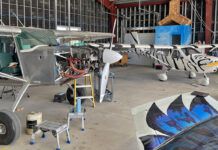
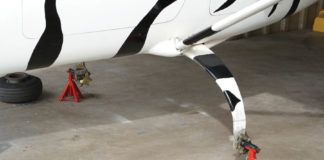
So, here’s where we are this month: The plane—my Jabiru J250 project—is sitting on the maingear with sawhorses substituting for the nosewheel and, with the lack of an engine as a counterbalance, another sawhorse under the tail. The elevator horn is finally attached, the control stick is installed, the brake master cylinder is in, the rudder pedals are there for my big feet, the throttle linkage is under my knees (but will be moved), and the flap actuation system is in the ceiling. Would you believe that this kit has been under construction for just two months? I’ll give you a moment to recover… You’re back? Good.
In all fairness, I have to offer a calibration. I have a large hangar out behind the house, I’m retired, and I have a large workshop with a lot of tools, so this will take the weekend/evening/garage builder longer. But it is amazing how fast it goes.
Now I’ll offer the caveat (one familiar to many builders): 90% done, 90% to go. That’s not a sarcastic criticism, just recognition that it’s really quick to get it to the stage where, as is commonly and quite accurately said, you can sit there and make airplane noises.
Winging It
You’ll note that the wings and tail aren’t included in that first list, so let’s get going on those by drilling a 1.125-inch hole in the top of the aft end of the fuselage for the wiring to the tail-mounted radio antenna. The vertical stabilizer will cover the hole when that’s done, so absolute positional accuracy is not paramount.
Even so, this is a bit intimidating, because unless you’re experienced with composites, you don’t realize how easy it is to recover from mistakes. I didn’t goof here, I’m only saying this to give you some consolation when the anxiety level is high and you’ve spent two evenings just staring at it, as I did.
It’s good that I did, because I went back to that cross rod in the ceiling and found that the mounting blocks were loose; the epoxy didn’t stick. That’s the bad news. The good news is that there is some redundancy built in via the screws to hold them to the fuselage, and because they go through a fairly stout area, the rod will be held in place even if not perfectly. Still, I wanted to see what was wrong.
It took four attempts to get the mounting blocks to stick. The first try used a dry flox with epoxy wash on both the fuselage and block. It popped right off. For the second try, I used a wet flox and wash with the same result. It did create a nice conformal piece between the flat block and the curve of the fuselage, so for the third try I blended some flox into that Jabiru superglue called Araldite. No cigar. It set up too fast due to the thickness of the gob along with the 100° F in the shop.
I went out the next morning in the cooler air and, with more working time, had success. I’ll add the caution that for this last attempt I applied a thin coat of grease on the cross-shaft. I thought I was being careful, but it would be more than a little annoying to have the whole system nicely bonded into place.
Why was it so difficult? I can only guess that surface preparation was inadequate, meaning I didn’t sufficiently sand the area on the fuselage. Take that to heart. You can eyeball-verify a good rivet, but it’s tough to qualify an epoxy bond. Preparation is everything.
Belting It Out
Where to next? Seat-belt mounts! These were quite easy. The lower ones were a simple job of fabricating a large backing plate from the supplied glass and then bonding it behind and below the seats. This time the instructions were spot on.
The position for the upper plate for the shoulder strap is left largely to the builder. You’ll remember my buddy Gene from the first installment of this series? He’s 6-foot-7, so I used him as the model. It might be, on reflection, too high for a 5-foot-7 pilot, but I didn’t want the strap going down below my shoulder when I add the upholstery under me at 6-foot-2.
The seat-belt mounts, as well as the rest of the airframe, are strengthened by the addition of flat gusset plates between a pair of vertical fuselage ribs. I’d suggest this should be done early in the process because they’re easy to fabricate and install and, hence, good for the beginner.
A Big Flap
Installing the flaps onto the wings came next. This is the single scariest part and rightly so. If you get an opportunity, look closely at several finished Jabirus and talk to the builders about their experience with the flaps. You’ll likely be met by rolling eyes and invitations to sit down over a beer. The problem is that it’s not a simple case of positioning the flap and adding the hinges. Why? Because, as delivered, the flaps don’t fit. You’re going to remove a substantial amount of material on the trailing edge of the wing.
The leading edge of the flap should fit into a recess on the trailing edge of the wing, but it doesn’t. The instructions direct you to clamp a couple of 2x4s to the bottom surface of the wing, then lay the flaps on the 2x4s. Then slide the flaps forward to achieve a close fit between the leading curve of the flap and the trailing curve of the wing socket. Simple enough, but the upper trailing edge of the wing comes down too far, so you’re directed to grind off that edge until the flap-to-wing clearance is right.
The problem is that you risk removing the joint between the upper surface of the wing and the curve going down around the flap. This was explained to me, but I didn’t understand it until I got into it, so don’t feel inadequate if you have to re-read the directions and study the photos and diagrams.
In the end, I chickened out and let the flat surface of the flap drop about an eighth-inch below the flat surface of the wing. To get the two surfaces co-planer would simply have removed too much of the trailing-edge joint. I looked at a half-dozen other Jabirus, and they were all more or less the same.
I began with the left wing and, per the instructions, started grinding the wing trailing edge back. I went too far laterally, though. The grind-back was needed only for the section that interfaced with the flap, and I extended it about 2 inches into the aileron area. Again, the forgiving nature of composites showed itself. I was able to repair this by first clamping a flat, tape-covered bit of aluminum to the upper surface of the wing, which gave me a stable surface for the subsequent glass. I added some flox to radius the sharp corner between the wing and the tape, and then added three layers of glass to the mis-ground area. When it had all set the next day, I simply popped the aluminum off and ground off the excess. It worked beautifully.
You’ll find that as you get into this project, or any other involving a new medium, you’ll gain confidence with increasing skill and knowledge, and what might have initially scared you, morphs into a challenge, then an annoyance, and later just a part of the project.
As it turns out, that evolution of confidence came to the fore when I fitted the right flap only to find that it needed no grinding at all. That left me with a step in the trailing edge of the left wing and no step on the right. Ugly!
OK, no grinding is an over-statement. After the hinges were in place I sprayed the wing socket black and used rubber cement to attach some abrasive paper to the flap. It was now a simple matter of working the flap up and down until all was quiet. The paint was removed where there was interference, so I didn’t need to replace all the paper as it wore out—just the area of the high spots.
Speaking of hinges, let’s look at those. Did I mention that virtually all of this wing work has been done with the wing upside down on sawhorses? You’ll need at least six for this project: two for each wing and two for fuselage.
The flap hinges are supplied as 180° curved plates marked with a fat, felt-tip pen. (I do wish they would use a finer line.) It’s a simple job to bandsaw them, but don’t drill any holes just yet. With the flap held in place with clamps and tape, you’ll remember to pull off the peel-ply at each of the four stations where the hinges will be attached.
Preparation Is All
I said it earlier, but it’s worth repeating: Surface preparation is everything, especially here. And remember that Jabiru must have run out of dark red material because I found light blue peel-ply here. It is almost impossible to see under the gelcoat, so it’s important that you make sure that you’ve gotten down to a clean glass surface before mixing epoxy. The alignment of the flap hinge is easy. Just slip them over the other half of the hinge located on the flap, and then trim the interface between hinge and wing until you get a good fit.
The next step is made easy with a bright light in a dimly lit shop. Shine the light on one side of the hinge, and you’ll see a shadow around the existing hole. Mark this carefully and then drill it with an eighth-inch drill. You’ll be able to then enlarge this pilot hole to make it match the existing hole.
A small brass insert is needed as well. It’s in the kit, but it’s not identified and not in the instructions. Thinking will see you through, though. If you simply tightened the hinge bolts you wouldn’t be able to move the flap. The brass insert protrudes beyond the hinge assembly so that the bolt tightens on it, not on the flap hinge.
Now recheck the position of the flap relative to the wing and glue the forward end of the hinge into position with Araldite. It will take about 15 minutes to become rock hard, so by the time you finish the last one, you can start the process of laying the supplied glass over the wing end of the hinges.
Once the flaps were fully installed I was able to expand on that taped aluminum idea and fix that jog in the trailing edge of the left wing. It was, putting it politely, a visually unacceptable anomaly.
With the wing right-side up, a layer of tape across the top of the installed left flap, a bit of sanding to prepare the too-short trailing edge of the wing and some flox to fill the radius was all that was needed to let me lay down three layers of glass between the wingroot and the aileron.
It took some leverage, a thin steel blade and some grunt work to pop the aileron loose, but it did come off; epoxy just won’t stick to that clear packing tape. I then used a carpenter’s snap-line to mark the trim line of the new trailing edge and a long-board sander to shape it.
The result turned out to be so good that I’m tempted to fill the right one after I get that FAA sign-off. As I write this, it’s late July and the deadline is eight months away, but with this rate of progress it shouldn’t be a problem (he said with unbridled confidence).
Forward with the Firewall
Jabiru ships a large, flat sheet of stainless steel trimmed to fit the wood firewall. Why didn’t they just bend this? The instructions advise doing it with a bench brake made of 2×4 wood. While that would yield the right radius on the bends, I have access to a professional quality sheet-metal brake, so this should be a snap.
I wrongly assumed that the two bends on the firewall would be parallel. They are not. Jabiru would have to custom-bend the stainless steel for each and every firewall, so they leave it up to you.
The proper way to do this would be to lay a thin bit of poster board on the upper surface and mark the outline. Transfer that outline to the upper end of the sheet metal and bend it. Now put the sheet metal on the upper/mid surfaces and mark the lower bend line.
In all fairness to Jabiru, they did tell me to do it in a fashion similar to this, but I succumbed to the lure of a pretty drawing. The problem with even this method is that you must take into account the radius produced by your brake rather than the radius required. To do that, mark the midpoint of the bend, not the start or the end.
I had to hammer out the lower bend and then, using the brake, re-bend it. Thankfully, I got it right on the next try, but it was embarrassing. The only advice I can offer is to be really, really careful here. Think it through, double check everything and then chant your mantra while doing it.
Let’s go back to the other end of the airplane and install the elevator trim control. This was not too difficult with the photos in the manual and some thought. Once it was installed, I did find some interference between the moving arm and the fuselage. This was caused by my having to cut off the horn, thereby making it shorter when I re-attached it. A small divot in the surface of the fuselage seemed the best solution. You will get the horn position right the first time, though, so this should not be a problem.
I will wrap up this month’s efforts by going to the wings for an easy project. Each wing has a fitting for an electronic fuel-level sensor. They are not needed if you want to rely on the sight gauges, so I installed the supplied plug/caps. It’s simple enough, so I won’t go into the details other than to caution you that there are several openings on each wing, so be sure to choose the right one. The photos in the older manual were hard to decipher, but the ones in the new manual are a lot better.
Next month we’ll continue with the wings and the fuel system. I’ll also get into fitting the fuel caps, a project that proved to be a major disaster for one builder when he cut into the mainspar. He passed on a tip that makes it substantially safer… Oh, all right, here it is: Darken the shop and put a bright light under the wing. You’ll see all the ribs and internals better than you would in an X-ray. Now you can drill the hole in the surface, not in the wingspar. I’ll show the photos and explain it in detail next month.
For more information on the Jabiru J250, call 559/431-1701, or visit http://www.jabirupacific.com/.


