It might not surprise you that I was probably the only kid in my junior high school who owned a copy of Abbott and von Doenhoff’s “Theory of Wing Sections” and kept it in my locker. It certainly surprised me (at the time) that no one else would have such an essential document at hand. Of course, I didn’t get many dates either…but I sure did know, from a very early age, that airfoils stalled when they reached a critical angle of attack, and not at some magic speed. Even when I started flying lessons in real airplanes a year or so later, I never really dealt with a stall speed; I was flying from the back seat of a J-3, and what instruments I could see didn’t really work very well. We flew by feel and knew when the airplane was going to stall. We didn’t need or think about fancy angle-of-attack indicators, even though we knew that AoA is what governed our ability to stay aloft.
I have made my living in the flight operations and testing world for decades, and have had the opportunity to fly many interesting things: real airplanes, simulated airplanes, and stuff that is hard to classify. Some were flown by feel. Some were flown purely based on what you saw on the instruments—including angle-of-attack measurements. In some cases, AoA was the most important instrument on the panel, and you did everything based on that. So I know the value of a good AoA system, and I appreciate what it can do for me. But when I got back in my own Experimental/Amateur-Built airplanes, I simply didn’t fly by it. I have nothing against it, and even have a computed AoA system on the Grand Rapids EFIS in my RV-8. I helped test the software, and I went so far as to install an LED repeater on the glare shield for a while to try and make myself use it—but to no avail. It simply wasn’t a regular part of my scan pattern when in the traffic pattern or on approach. So, I was a believer, but I wasn’t a practitioner, when it came to AoA.
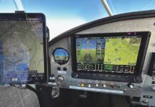
The AFS Pro indicator head can be mounted in the panel or on the glareshield—a position favored by the author so that it is visible on approach.
Then I met Jerry VanGrunsven, brother of Richard “Van” VanGrunsven of RV fame. Jerry has been flying all his life and retired from a major airline after decades of flying a wide variety of aircraft. He currently flies an RV-8A, and has undoubtedly flown pretty much every one of his brother’s designs, as well as countless other certified and homebuilt airplanes. When we got together by accident in Aurora, Oregon one morning last autumn, he was excited to talk about the primary flight instrument in his RV—an Advanced Flight Systems AoA Pro angle-of-attack indicator. Mounted prominently on the center of the glareshield of this tandem-seating aircraft, it was impossible to miss —and clearly dominated the otherwise sparsely populated panel, which didn’t include an analog airspeed indicator. (It does have a Rocky Mountain Instruments digital instrument, which displays airspeed and altitude, along with other data.)
Jerry was anxious to talk about AoA because he is a true believer—one of those people who is passionate about sharing his belief and experiences. Before I knew it, we were going around and around over the green Willamette Valley, rolling and pulling to exercise the AoA system to its fullest. And for some reason, this time, AoA clicked—my brain responded to the indicator, and the only reason I looked at airspeed was simply to compare it to what the AFS display was telling me. We ran the gamut of flight regimes, including accelerated stalls, and by the time we headed back to the airport, I was sold. AoA in Experimental aircraft isn’t just a curiosity; it is something that can help anyone fly more precisely and more safely. I didn’t even wait to get home before ordering a system for my RV-8.
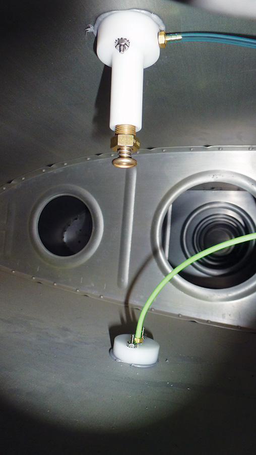
The sense lines connect to upper and lower ports attached on the wing surface near the tip. The ports can be attached using screws or pro-seal, and can be added to a completed aircraft quite easily.
Installing the AoA Pro
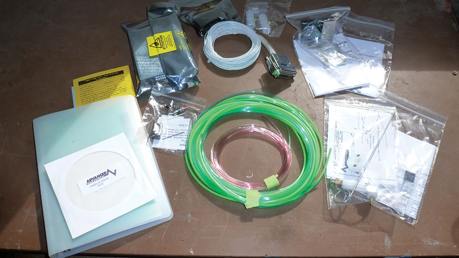
The AoA Pro system from Advanced Flight Systems is a well-packaged kit, with a variety of sub-kits carefully tailored to your specific application. For instance, I chose a glareshield mount for the indicator in the RV-8, and the box came with exactly the right components (in separate bags) for that installation. The brain box even has a label that says that it has been pre-calibrated for the RV-8 (assuming that I put the sensors in the recommended position). It does go on to say that calibration checks should be performed, but based on feedback from other users, I expected it would be very close—it turned out to be spot on. The instructions are well illustrated, and it didn’t take long before I was ready to tackle the project. As for completeness, the kit even comes with a #60 drill bit for the sense holes, which is useful since we all know that we have broken the #60 in our drill bit sets long ago. AFS also provides kneeboard cards printed on heavy stock for post-installation checkout flights; they really have thought of most everything that you will need.
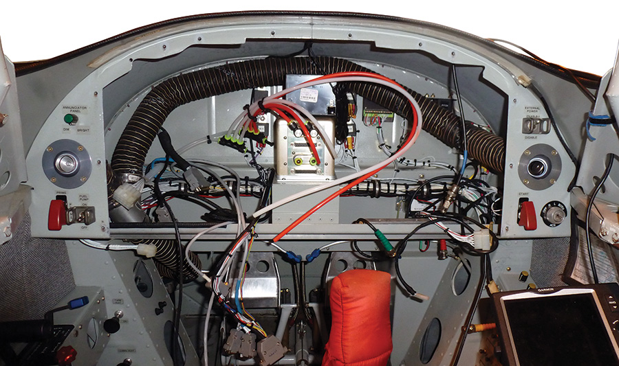
The value of a removable instrument panel is that retrofitting new equipment is simple. The installer can sit in the pilot seat rather than hanging upside down.
Since I was doing the installation on my already-flying airplane, the first thing I needed to do was gain access to the wing and fuselage areas where I needed to work. This really just meant pulling a wingtip, the wingroot fairing, and the floorboards. The basic installation requires that you add two pressure sensing ports near the wingtip, the brain box, a flap switch, and the indicator. Two small push-buttons finish it out. The small-diameter AoA pressure-port lines need to be routed to the box, as do a pitot and static line, which you tee off of the existing system with special fittings supplied by AFS. There is a pre-made wiring harness included in the kit that attaches the box to power, the indicator, switches, and the audio panel. Once I had the airplane opened up, it was clear that the best location for the box (in my airplane) was behind the panel. This allowed short wire runs and fewer (smaller) bulkhead penetrations to add the tiny pressure sense lines.
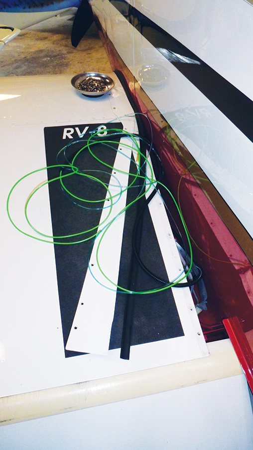
Installing the sensor ports on the wing took about an hour (not including removing and replacing the wingtip and intersection fairings; add a half-hour for those tasks). To run the soft tubing through my completed wing, I picked up some small corrugated conduit, ran both upper and lower tubing through that, and then pushed it through lightening holes in the ribs to the root. I was able to access the intermediate positions to tack the conduit down through inspection plates along the span.
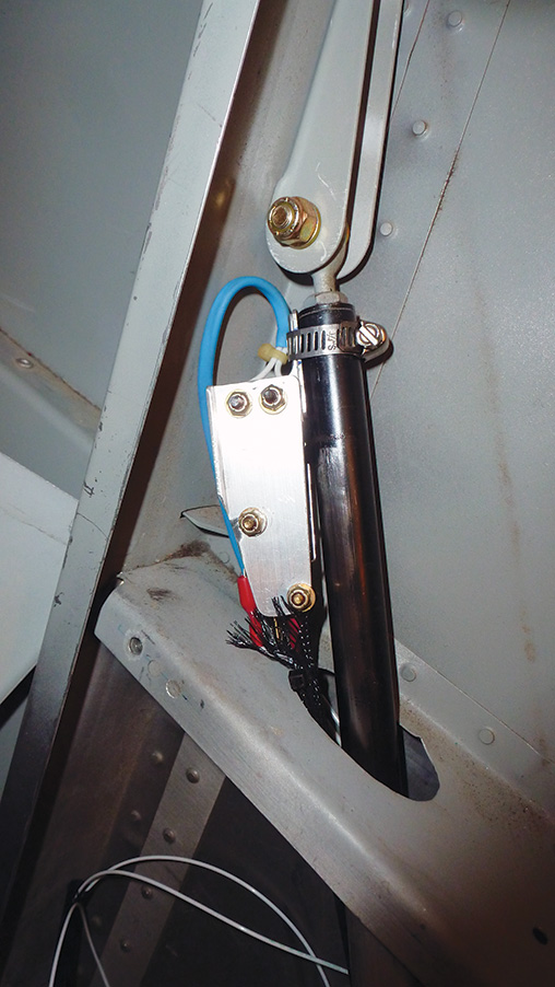
Since the lift curve and chord line are different with the flaps up or down, the AoA system needs to know where they are; a simple microswitch attached to the actuator or linkage is the easiest way to do this. AFS recommends a switch which closes (providing a ground signal) during the first third of flap deployment. On the RV-8, this was fairly easy to rig, but each aircraft will, of course, be a little different. For most, the hardest part will be running a wire through your airframe to carry the signal to the brain box.
My removable instrument panel again showed its worth. Once it was pulled out (a five minute job), I was able to sit comfortably in the cockpit and add wiring and pitot/static taps with little effort (and only a few bad words). I used the glareshield mounting bracket supplied by AFS for the indicator and put a grommet in the glareshield for the indicator cable. The bracket was mounted with double-sticky tape to hold it straight, and a single #8 screw for strength. Planning ahead, I put a short length of black heat shrink over the white shielded cable so the portion above the panel would be black, instead of white, which would be visible as a reflection in the windscreen. Plan ahead though; you need to put on the heat shrink before you route the cable through the back of the indicator and then install the connector pins on the end of the cable. It’s a serial operation. And speaking of those connector pins, it pays to have the correct crimper to make installation possible. They are the tiniest open-barrel amp connectors, and a magnifier lens helps when crimping them in place—they are that small. It is certainly within a homebuilder’s skill set, but it takes care and patience to do them right. Mounting the brain box was simple in my case; I had a great spot on top of the avionics backup battery that was just the right size. A piece of sticky-back Velcro keeps it in place.
I chose to connect the audio to the unused marker beacon input in my somewhat-dated audio panel. This allows me to keep the audio from the AoA selected with the latching switch, and also allows me to quickly silence it with a single button push. I left the volume potentiometer on the AoA box set where the factory put it, and it turned out to be a good match for the rest of my audio inputs and the Halo headset.
In order for the AoA system to know if the flaps are up or down, a microswitch needs to be added to the actuator.
System Checkout
There is always a moment of hesitation when you apply power to an airplane after installing a new piece of avionics. You ask yourself if it is going to light up as expected—and you ask yourself what you’ll do if you get a smell of smoke instead. In this case, I was pleased to see the display light up and hear a faint call of “Angle, angle, push!” coming out of the headset that was hanging on the side of the cockpit. These two signs meant the brain box was working, the display was wired correctly (remember those tiny pins?) and that I had indeed found the right pin for the audio panel. A push of the dim button made the display half as bright, so I knew that the controls were working; all that was left was to pull out the pre-printed checklist, run through the specified ground checks, and go for a test flight.
Because the brain box came pre-programmed for the RV-8, the check flight consisted of flying a decelerating glide to see where the initial warning sounded and then comparing that to the computed margins above the known stall speed of the airplane. Since it had been a number of years since I had done the Phase 1 on the airplane, I decided to re-establish the stall speeds (flaps up and flaps down), to make sure that the airspeed indicators (analog and EFIS) hadn’t drifted. I performed a series of five power-off stalls, recording the buffet and break speeds each time, then averaged the results to establish the current stall speed of the airplane. The spread was only plus or minus one knot, so I was confident that I had good numbers. These were then multiplied by a margin of 1.14 to reach the value at which the indicator should reach the bottom of the red chevron, and the audio warning should sound. I also multiplied the speed by 1.3 to get my normal approach speed, which should occur when the AoA indication was right on the green donut in the center of the display.
Once I had these numbers (I let the autopilot fly as I calculated the numbers), I flew the same series to see what the AoA was indicating. Sure enough, it was within a knot or two of being dead on. Given the variation between homebuilt airplanes of the same model, I declared victory and put away the card that would have had me fly a zero-G flight path to do a full calibration from scratch. In a way, I was almost disappointed in this; it sounded like a fun sequence to fly. The checklist warns you to secure anything that might float loose in the cabin before the maneuver. Adjusting the calibration of the unit for a specific, non-pre-programmed airframe is a simple step-by-step process, using the two push-buttons and specific flight maneuvers to customize the box. Although I didn’t have to perform the sequence, I have talked to many builders that have, and none reported significant problems when they followed the procedure.
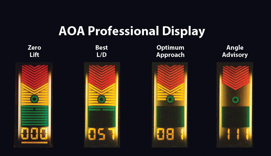
This image from AFS shows how the AoA Pro looks under various flight conditions from zero lift to the warning zone before the stall.
Flying with AoA
With the calibration verified, the next step was obvious: do some loaded-up maneuvers and see how well the system worked at the hairy edge of flight. I started out with power-off stalls again—flaps up and flaps down. At first, the call “Flaps!” startled me each time I deployed them, but I quickly got used to this warning. It’s a good thing to have for those of us with flap switches on the stick grip; accidental deployment past a few degrees should be a thing of the past. In each case, the stall was preceded by visual and audio cues well before the break was reached. It would be very hard to ignore and actually stall the airplane and say that you weren’t warned.
Most people don’t accidentally stall airplanes in straight, gliding flight, so the real test came during turns. First, I performed pattern turns (which I usually do in an RV at about 45 degrees of bank) left and right. With a little pull beyond the trim speed, the warning came with plenty of margin. The light bars on the display seem well connected to the stick; pull back, and they disappear into the red, push forward and they safely descend into the green. As I pulled harder and harder, adding G’s, I eventually heard “Angle, angle push!” on a continuous basis and I was left with only one or two red bars. Banking to 90 degrees, I pulled some more and got that familiar shudder as the bars went away and we broke into an accelerated stall. The AoA proved itself in every way as a true stall meter; there’s no way you could miss what was happening, unless you weren’t looking or listening at all.
Of course, I fly airplanes that are aerobatic, and I was interested to see just how this system would do when the world is upside down relative to the airplane. I have found that while the calculated AoA system on the Grand Rapids EFIS is quite accurate on approach, it really doesn’t do well with unusual attitudes. While I am sure the equations are adequate, the rate at which attitude and airflow changes is probably too fast for it to keep up; it simply gives up and goes to lunch while the pilot is trying to lose his.
Matching your Mission
It should be noted that not all AoA devices are created alike; there are different displays and different methods of determining current angle of attack. In addition, some systems use audio more prominently in their presentation of AoA data to the pilot. The way you are going to use the system might determine which one you choose. For instance, if you spend a lot of time circling at low altitudes, perhaps taking pictures or scouting moose, you might not be looking forward. In that case, an audible alert will be much more valuable, be it a variable tone or a simple discrete warning when you reach a certain margin below the stall. For those who fly regular transportation profiles, with little maneuvering other than normal pattern flight, a visual and/or audible display is probably fine. Even a calculated angle of attack produced by an EFIS might be more than adequate, as the attitudes and rates aren’t extreme. However, if you are interested in flying a lot of aerobatics, experience has shown me that the calculated systems can’t keep up during high-rate or inverted flight. So pick a system that matches what you need it for. The average pilot will find it most valuable in the airport environment and that is where I expect it to save some lives.
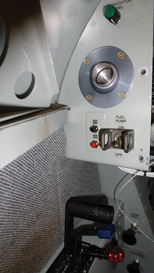
There are only two control buttons that need to be added to the cockpit—one for dimming and one for testing the unit.
I have found that the location and type of display has a huge effect on the likelihood that I will use the AoA in a particular aircraft. Quite frankly, it is hard to break old habits of where we look during certain phases of flight, and if you are used to looking mostly outside, then a panel-mounted AoA system is probably going to go to naught. In an airplane flown mostly via out-the-window views, a glareshield-mounted indicator is probably the only way to get yourself to reliably use the system, as it is more likely to be in your field of view. I would venture to say that most of the inadvertent stall/spin accidents that we are trying to prevent through the use of AoA systems occur in visual conditions, with the pilot looking outside, so strong consideration should be given to putting the system where you can see it, if it is going to do any good. Presentation is also important—and more information is not always better. Many Navy aircraft simply have three elements—an on target indicator in the middle and pitch-up and pitch-down indicators above and below the middle. It’s very simple. I have flown with multiple-LED indicators where the lights flash to tell you things as well as being steady, and I found these to be too busy for my brain to interpret. The AoA Pro seems to be a very good compromise between simplicity and giving more useful information—at least for me. From it, you can determine if you are on the optimum AoA, or by how much you are off. That’s all I really need to know at a glance. And finally, it is hard to argue with a stern voice telling you to push, if you have ignored all the cues that your margin has been decreasing, and you are truly about to stall.
Going Forth
So far, I have about 50 hours in my airplane with the display installed, and several of those hours have been in maneuvering flight where angle of attack really comes into play. I can honestly say that I have been surprised once or twice to find that a normal habit for me has brought me closer to the stall than I would have expected. Like Jerry, I have discovered that when we are distracted, or the airplane and environment is far outside our normal box, it is easy to let the margin slip away. It is sobering to read the accident reports and find that many loss of control accidents in Experimental airplanes happen to very experienced pilots; it seems that the laws of aerodynamics can catch up with anyone, regardless of the number of hours in their logbook. Angle-of-attack systems can serve to both help improve our flying precision and keep us well away from the razor’s edge, where mistakes can prove fatal. Old dogs can, it seems, learn new tricks, and I heartily recommend getting out and seeing what these systems can do for you. Who knows, you might become an evangelist yourself.

