 Last month, I walked through the block diagram of the Dynon SkyView HDX system—what you need to order to get certain functions and features—and now it’s time to put those pieces together in the airplane. A note or two before we start. This is a retrofit to an existing, flying airplane with an eye toward balancing a few key objectives. On one hand, you could say if you’re spending the money on a full panel redo, you might as well just rip out all the old stuff and start anew. On the other hand, there are systems in place that have functioned well for more than 1000 hours, so the benefits of rewiring the bulk of the airplane would be more for aesthetics and ergonomics than for any functional reason. That’s why I took a hybrid approach—mostly keeping what was there but moving some key elements around, thinking I was making it better. I’ll come back to that.
It is a different story if you’re starting from a bare airplane, and in that case I strongly recommend looking at other airplanes of a similar type to see how builders have approached electrical-system architecture and panel layout. Even better, look very closely at any factory-built system. Chances are most of the kinks have been worked out and you benefit from both a proven system but also from having an airplane built to an identifiable spec. Ask anyone who has sold a homebuilt: If your airplane is more “normal” than the next, it’ll probably sell faster. It’s not why you build an airplane in the first place, of course, but this is a consideration you should definitely bear early on.
With the SkyView system, I read every bit of the 590-page installation manual. (Maybe not every page but at least all those applying to my configuration. To say the system is well documented is a gross understatement.) From there, I began considering where each component in the system was going to be mounted, how that influenced wiring runs and what impact if any these choices might have on downstream maintenance. I’m telling you that considering maintainability now will cause your future self to thank you profusely.
Cutting Metal
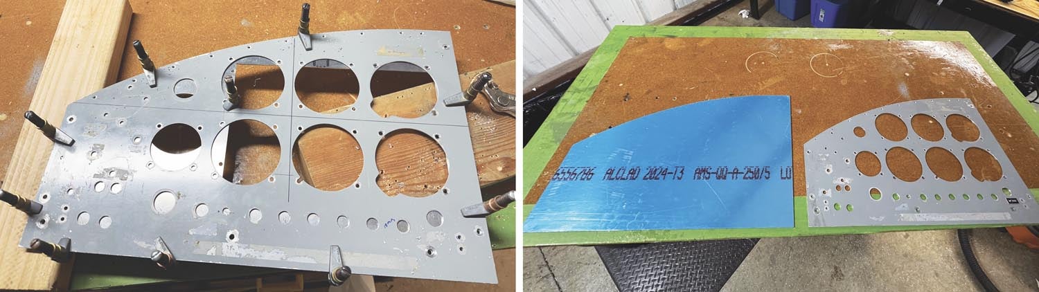
For me, some of the first steps involved replicating the metal panel components. The builder of my GlaStar made his own system of foldable panel pieces. Each outboard section (pilot and copilot sides) pivots at the bottom to allow better access. The panel above the radio stack is secured at the top and the lower panel, through which the engine controls pass, is secured by a lower cross tube in the cabin. I wasn’t going to recut that panel but everything else would be new.
I started by using a hand router to cut an outside blank in MDF (medium density fiberboard, in case you’re wondering) and then used that as the form to cut a new piece of 0.063-inch aluminum. I wasn’t super happy with the first iteration and realized it was better to use the original panel as the actual template and use the MDF as a sandwich to give the router’s bearing some room. From this, I created a new panel and began the first major cut, which is the large rectangle for the main HDX screen. Lots of ways to do this, of course, from a rough cut with a jigsaw or a Dremel cutoff wheel, but I also tried an internal cut with the router that was not as accurate as I wanted. No doubt by the 10th or 20th iteration, I’d have it down but I was beginning to lose patience. One quirk of the HDX is that the edge distance from the display aperture to the bezel is just a couple of millimeters along the top, so that top horizontal edge has to be exact. The sides and bottom have more overlap and provide some coverup for your being human with tools.
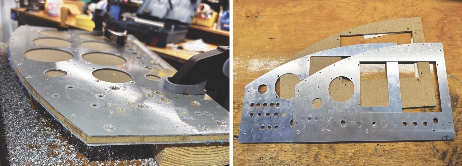
Instead, I decided to call the pros. Advanced Flight Systems, which is local to me, is a Dynon subsidiary and builds complete panels for a wide range of aircraft. I took my original panels over and Kyle George scanned them into a CAD file. From there, we worked through a couple of iterations, eventually deciding to move the main HDX display as far up as it could go, even so far as to crowd the 90° angle behind the top edge of the panel providing support along the top edge.
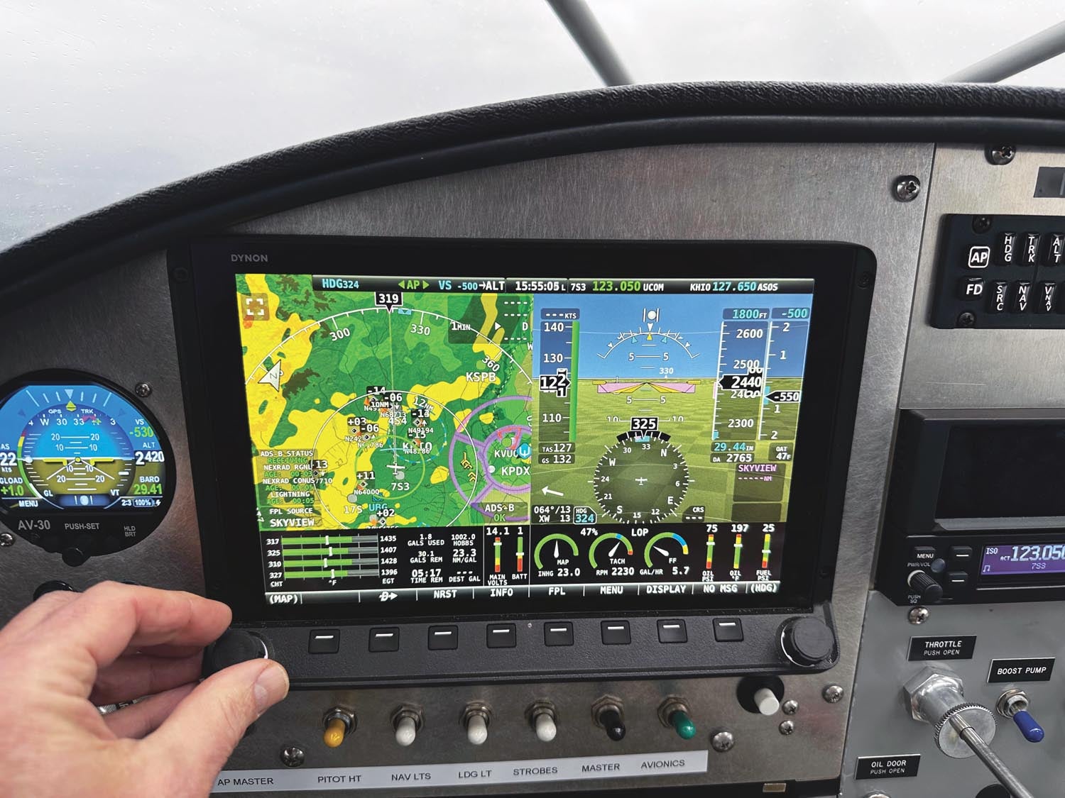
Moving the display up accomplished another goal: gaining room beneath the HDX screen for an existing line of switch/breakers. Which gets us back to that idea of not wanting to totally rewire the airplane. But here’s the catch. When you look at 2D drawings of the system, it may not be obvious that the lower lip of the HDX extends down and out by a bit more than an inch. When you start cutting for the screen you have to imagine that you’ll have to accommodate the bezel farther down and out than you might have just looking at the drawings. As an immediate matter, the original take on the panel had that lower lip interfere with the switches. (Having now flown with the system, I’m here to ardently defend the physical layout.)
Once I had worked out the right place for the pilot-side screen, AFS kicked out a beautiful blank with just the main-screen rectangle and a 3-1/8-inch hole for a backup ADI cut. I wanted the freedom to move the switch line and the location of some other components. Plus I wanted to be sure I was accurately transferring the mounting points to the new panel by using the old as a template.
More Distractions
I mentioned that I didn’t want to rewire the whole airplane, but just about anything related to avionics was new so that gave me a chance to experiment. In my GlaStar, like in many homebuilt and certified aircraft, the electrical system is concentrated in front of the copilot because that’s where the circuit protection is. In my airplane, the main bus forms something of a loop, with the switch/breakers in front of the pilot connected to the battery through a short lead through the firewall to the starter contactor. The alternator comes inside on the other side and feeds to the main bus bar on the right. (A separate avionics bus is switched from the main bus.) Obviously, charging the battery requires the alternator output to travel through a bridge wire (in this case, an 8-gauge wire) in this right-to-left bundle to connect the two. Already there were plenty of wires running around behind the panel.
I thought I could cut that down by locally circuit-protecting some components on the left side of the panel. So the USB power, aux-tank pumps, pilot-side HDX display, backup ADI, starter relay and E-MAG electronic ignition were brought together in the lower left corner of the panel. It helped, too, that these circuits wanted to be on the main system, not the avionics bus, and that a solid source of main power was right there. I succeeded in reducing the number of admittedly lightweight wires wending across the cabin behind the panel, but I also marooned breakers behind the mount for the iPad, which I intended to keep. I’m not sure it was worth the effort to reduce wire runs. Were I to do it again, I would probably only keep the E-MAG circuit breakers near the ignition switch, and that’s only because you occasionally test their self-powering feature. Oh well.
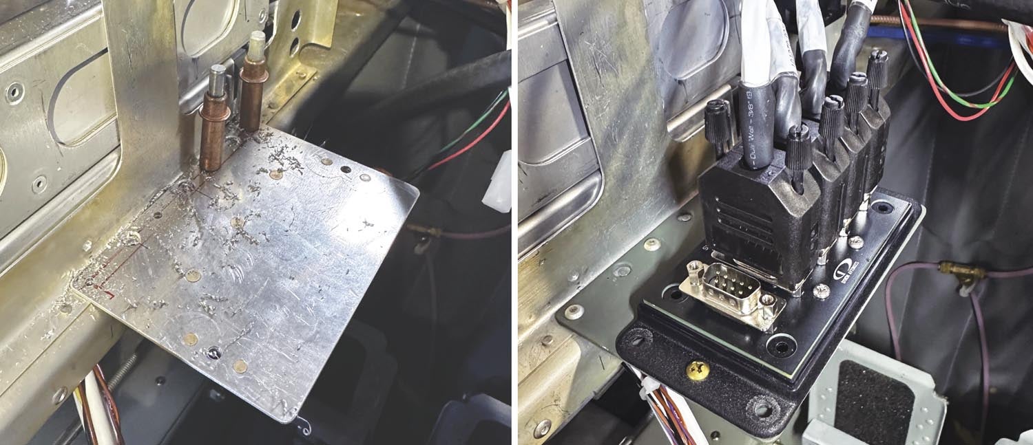
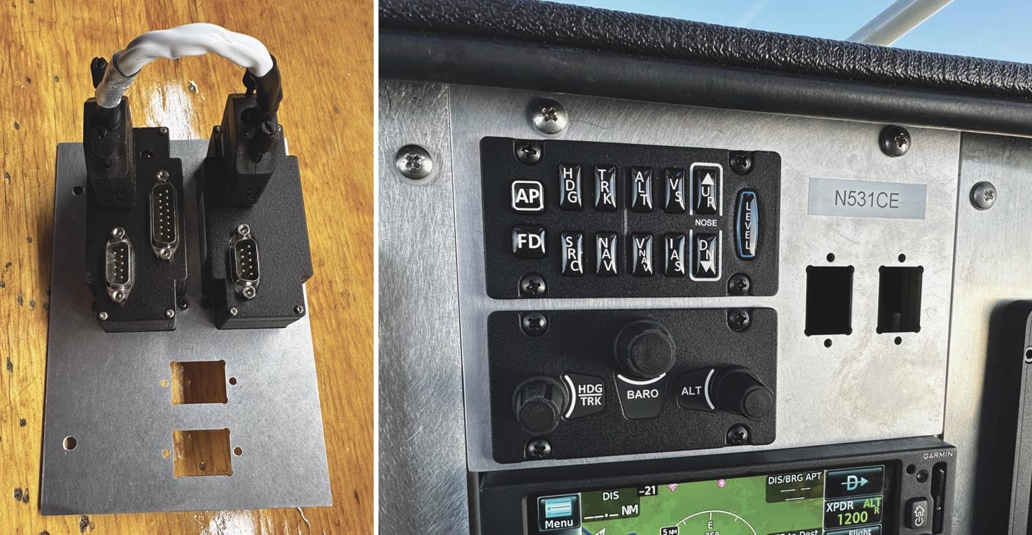
a small L bracket picks up the vertical face. Four of the five SV-NET harnesses are in place (right).
Mounting the Boxes
Because the SkyView system is so modular, you should give particular consideration for where you mount each component. I’ll describe what I’ve done in the GlaStar but that might not be ideal for your situation. Again, see what others have done before you start cutting metal. And keep in mind that accessibility should be high on your list, so leave room for each component—resist the temptation to “save space” elsewhere by jamming things into corners. You want to have access to each piece of the puzzle and you’ll need to account for any connectors.
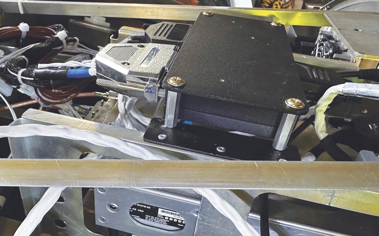
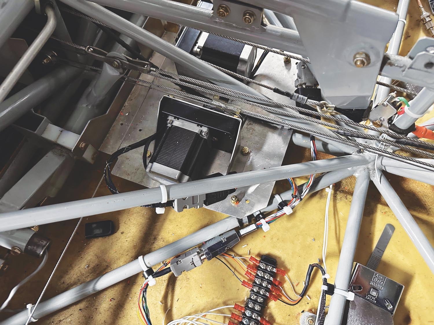
I had to move the EMS module so the connectors had vertical separation.
In SkyView, it’s typical that the DB-9 network connection comes out the long end of the module and the connector shells are 1.7 inches deep, but you also need to think about the bend radius of the harness itself. I recommend at least an inch from the end of the DB-9 shell to whatever surface the harness has to clear.
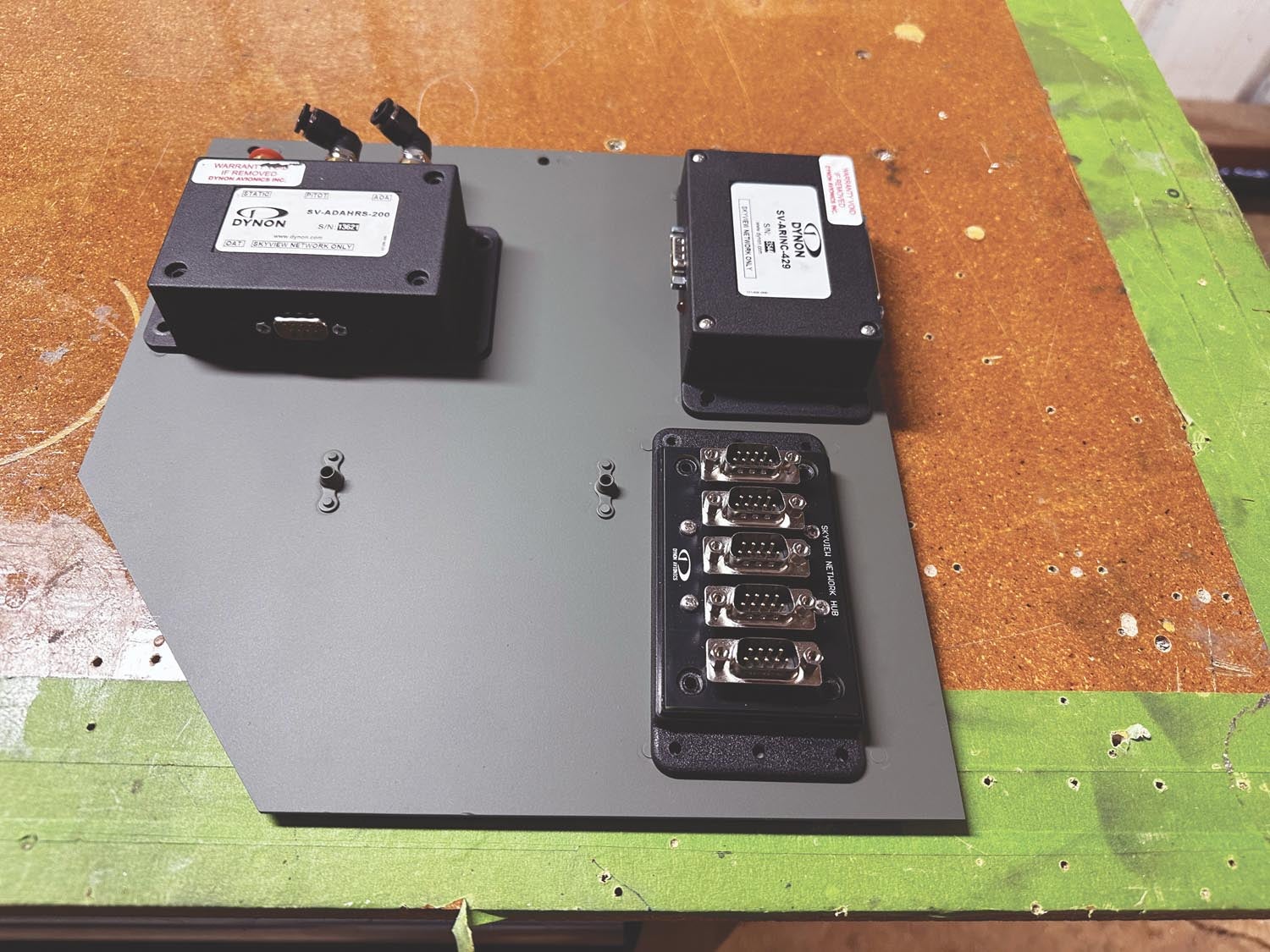
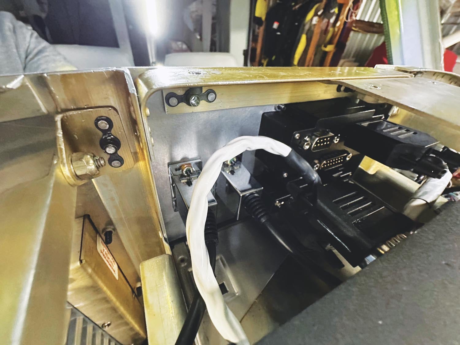
For the most part, you can put boxes where they make sense. There are a couple of exceptions. First, the SV-ADAHRS-200/1 modules need to be located within 1° of each major axis—level left and right, within 1° of the in-flight pitch attitude and within that margin to aircraft heading. You can make adjustments in pitch for the display but know that if you’re fitting the SV autopilot system the LEVEL button will try to drive the airplane to a totally level signal from the mounted boxes. By using the Dynon-supplied stacking kit, I could reduce the wiring and plumbing clutter as well as ensure they were aligned with each other.
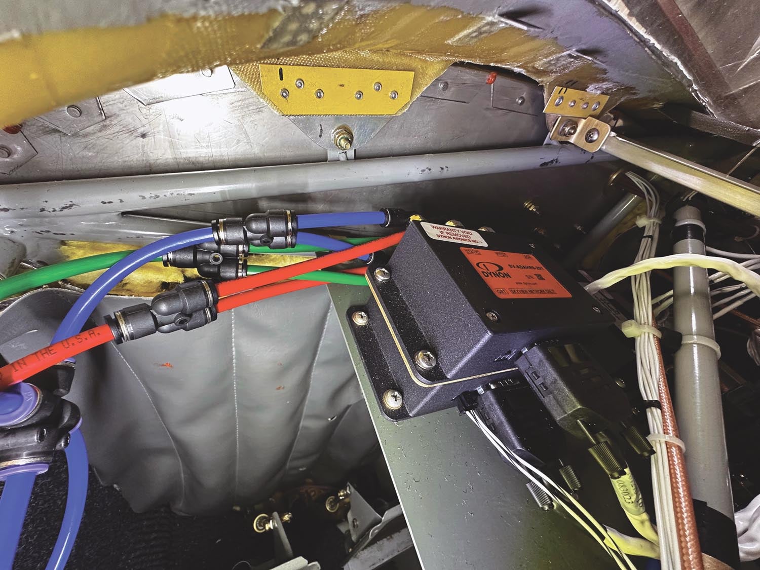
In my installation, the two ADAHRS modules were on a plate secured to a left-right tube on the cabin side of the firewall. They were joined by the SV-ARINC-429 module and one of the two SV-NET-HUB modules on the top and the backup battery for the primary HDX screen on the bottom. Now, assuming that fuselage cross tube was installed correctly back in, oh, 1998, it should be level laterally. I also know the in-flight pitch attitude, which I can relate to a known tube in the fuselage. And as long as the boxes are mounted square to the crossing tube, they should be in line with the long axis of the airplane. All good, but I forgot one thing when I installed the magnetometer in the right wing. (I knew from experience it’s a good place to put it, relatively free of interference.) I’d mounted it to the inside of the wing skin adjacent to an inspection panel and carefully considered where in the wing chord I would mount it so it would be at the same angle of incidence as the main ADAHRS. That much I got.
I forgot one thing: dihedral. The GlaStar wing runs a nominal 1.5° of dihedral and I’d mounted the module flat to the inside of the wing skin. Oops. Fortunately, a couple of thick nylon washers raised the inboard flange and got me to the desired range—meaning the magnetometer was now within 1° in all axes of the ADAHRS boxes. Oh, I had briefly considered putting the SV-MAG magnetometer in the tail cone where I’d had the equivalent Garmin unit, but the footprint was so different I couldn’t make it work. Word of advice—when you’re building mounting plates and brackets, go bigger than you think you need. If you build for today’s avionics, you might not be able to accommodate what’s best when you’re actually done.
Engine Matters
Where you locate the engine-monitoring module depends on many factors, but I have some thoughts here, too. (You’re surprised?) I’d started with a Dynon EMS-D10 mounted high on the copilot side of the panel. I didn’t like that location and moved it to the top of the radio rack, which gave me more of a kink in the service loop than I’d had before but an acceptable amount. Now, with the SV-EMS-220 module performing the same function (but not tied to any panel location) I had some choices to make. The easiest was to keep it in about the same place, which I did with simple brackets that allowed the box to span the top of the radio rack. It required the harnesses to make a deeper S-turn from there to the firewall penetration, but I could live with it. It was only after a later change that I had to move the box even closer to the firewall and considered re-terminating the wiring at the engine side and pulling more of the harness through.
For a new installation, again I suggest following the most popular choices for your airplane design. But always leave yourself a margin of service loop. You need access to the module, room to remove both the 37-pin main plug and the 25-pin EGT/CHT harness—and neither of these is exactly flexible—and space for the DB-9 SV-NET connector on the opposite long end of the module. This could have been much harder, of course, had Dynon not duplicated virtually all of the connections pin-for-pin from its legacy offering. I removed a few wires and reallocated the power-in wire to a main-bus location because that’s how the SV-EMS-220 reads ship’s voltage. It is, like most of the other SV boxes, actually powered through the SV-NET cable.
Knobs and Such
My original plan, looking at the way the HDX’s multi-function knobs on the lower corners of the display could be configured as well as with an eye on available real estate, was to have only the autopilot control panel external to the displays. It works great in the originally envisioned location, at the top of the radio stack, but after flying a few hours I realized the experts tapping me on the shoulder and asking, “Are you sure you don’t know the knob panel?” were on to something.
So I’ll say this after flying both configurations: You want the knobs. They give you direct access to the altimeter setting (baro) and heading and altitude bugs, and free you up to configure the screen knobs for other features. (When you’re looking at a moving map, that knob is always dedicated to the map anyway.) It’s 100% the way to go, plus the location of the knobs and the AP control panel near the top center of the stack makes my little GlaStar feel like some kind of tiny, exceedingly slow airliner. Ergonomically, this is a win.
Adding the knob set reveals one of the genius aspects of SkyView. Because most modules run through SV-NET, adding a new one means just having an open slot. Find the nine-wire network harness the right length, drop very shallowly into the setup menus to configure it and you’ve added a new feature.
Autopilot Setup
Fortunately, I had a TruTrak autopilot in the airplane previously, so the Dynon servos slipped right into the existing mounts. Note that if you’re a GlaStar owner, you’ll need to make the base plate that rests on the lower cage as well as the 90° bracket to connect to the servo bodies. The Dynon capstan servos come with the basic mounting hardware and bridle cables.
Once installed and wired—the main distinction here is that the power, ground and disconnect wires are separated from the network wires, and that Dynon will sell you a specialized AP connection harness properly configured—the AP was up and running quickly. You drop into the hardware setup section and follow the on-screen prompts, which have you place the controls at the four extreme corners and press a button each time. From that, the system determines the operating range and the orientation—does the pitch servo have to push the “right” way or reverse?—and that’s all there is. I started flying on the baseline settings and was really surprised how well it did. Real-world fine-tuning is ongoing but the documentation is thorough and clear. As long as you keep good notes, refining the system should be straightforward.
The Last Bits
I gave a lot of thought about where to mount most of the items, considering ergonomics as well as wiring efficiency and serviceability. I went back and forth on the SV-ADSB-472 module, which brings ADS-B In to the SkyView system. Did I want it behind the panel with a relatively thick RG-400 coax cable heading off to the antenna under the copilot seat? Or would I put the unit next to the antenna but need four 22-gauge wires (power, ground, data in, data out) to meander toward the panel? In the end, I had more room under the seat, so that’s where it went. For builders starting from scratch, I recommend giving all remote modules a bit of room behind the panel, rather than scrunching or stacking everything too tightly. You never know when an extra inch or two will help make a future upgrade easier.
Finally, I thought I’d learned a valuable lesson from my Sportsman project prior to 2010. It had three significantly different panels in the time I owned it—call it an occupational hazard—and each time I assembled the new parts, painted what needed to be painted and began the troubleshooting. In every case, changes were required that either forced some touch-up work later or a complete repaint of a panel. This time, I’d be smarter. Bare metal through the first few hours. And guess what? Everything worked the first time out. Every single thing. In the first hour of flight, having reset a couple of software parameters and refined a few displays, I sat back, folded my hands in my lap (the autopilot was flying) and groaned. There was nothing left to do.
Except tear it out and paint it. As soon as the sun comes out again in Oregon, that’ll be next. I already have placards from Aircraft Engravers ready to go. But for now, I’ll just enjoy the results of a complicated but understandable—and ultimately very successful—transplant operation.
![[Credit: JetStream Rider]](https://www.kitplanes.com/wp-content/uploads/2026/04/AdobeStock_345999332.jpg?w=218&h=150&crop=1 "2026 Avionics and Lights Buyer’s Guide")
![[Credit: Radiant Technology]](https://www.kitplanes.com/wp-content/uploads/2026/04/550095_5165745cc27748a598699799d796fd94mv2.jpg?w=218&h=150&crop=1 "Radiant Technology Unveils SafeGyro")
![[Credit: Dynon]](https://www.kitplanes.com/wp-content/uploads/2026/04/EMS-stand-alone_HDX.png?w=218&h=150&crop=1 "Dynon Unveils Scalable Engine Monitoring for Kitbuilders")


