It was a perfectly wonderful Oshkosh ’16. Weather wasn’t horrible, mosquitos were way down, airplane registrations were up, food on the field wasn’t half bad, and if I may say so, the forums were very well attended.
However, if you didn’t make the trip to “Wonderland on the Winnebago” this year, you may have missed some very interesting forum topics, one of which we will talk about this month: wire identification.
With the explosive growth of aircraft electronic devices, major changes in lighting, and a general overall increase in electrical and electronic devices, has come a major increase in the amount of wiring in our aircraft. While it is not common in light aircraft to identify the wires as it is in large turbine aircraft, it is still a cheap, easy way for you to keep from spending literally hundreds of hours later troubleshooting the electrical system in your aircraft if both ends of each wire have a unique identification. This is about the least expensive of any way I’ve been able to come up with.
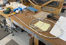
The basic idea is to print a whole bunch of sequential numbers in a word processing program (there are automatic serialization routines in Microsoft Word, ask any fourth grader how to do it) and then print those numbers onto small return address “sticky” labels cut to size.
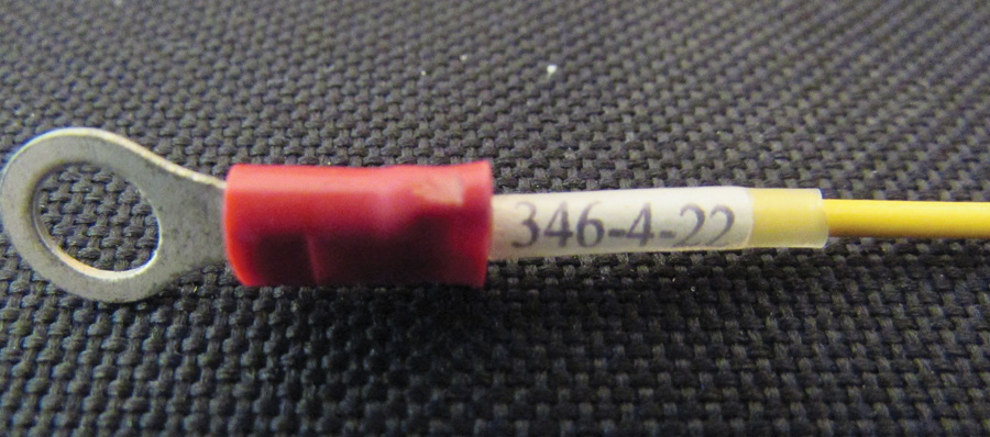
If we simply stopped here, the first time those labels got wet or treated harshly, those idents would be long gone. However, if we use clear shrink sleeving over the wire, then both the label and the numbering should last for a long time.
The last remaining problem is what numbers to use. So far as I have been able to determine, there is no standard numbering system, so I’ll throw out something that seems reasonable. If anybody wants to elaborate on this idea, I’ll be glad to post it as an update on my personal Kitplanes page (www.rstengineering.com/kitplanes).
How the System Works
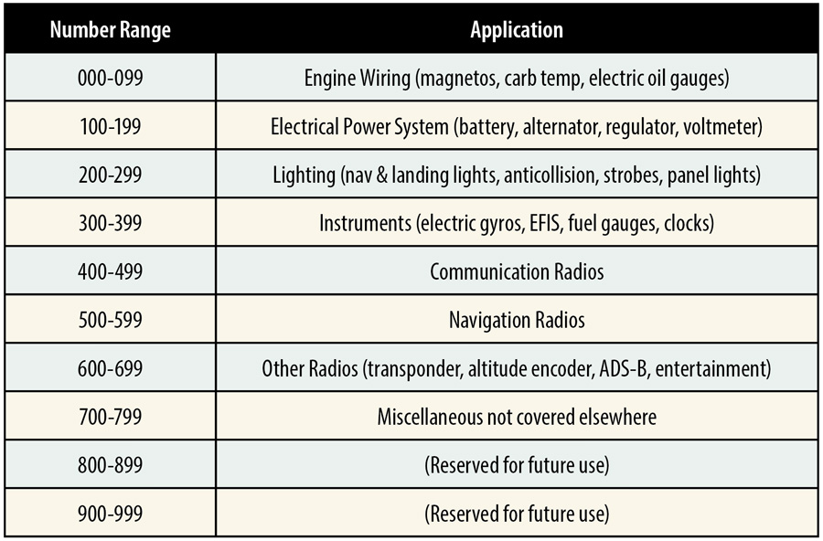
Figure 1 shows the number range used for each application. As an example, the range for wires connected to instruments, such as electric gyros, EFISes, fuel gauges, clocks, etc., is 300-399.
Looking at Figure 2, we see that the 46th wire in the instrument category goes between the right fuel gauge and the sender. Those of you who are proficient in Excel will probably make up a similar table for your own wire assignments.
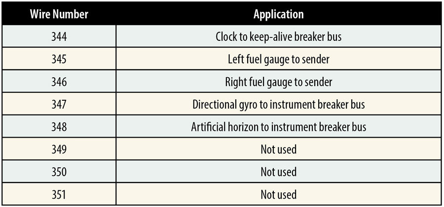
Figure 2: A small sample (#344 through #351) of individual wires in the instrument category. The complete range of wires for this category goes from #300 to #399.
And for those of you who have taken my advice to download the free schematic drawing program from my college web site (www.rstengineering.com/sierra, then click on MECH14 and download CMTM PCB & Schematic), here is another reason to do so.

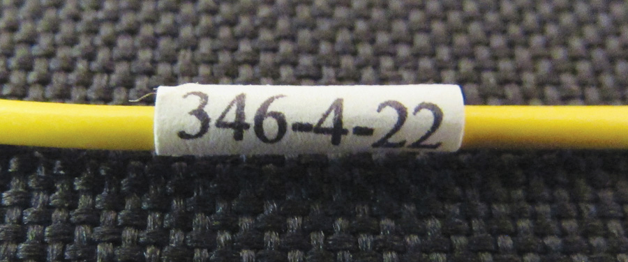
Figure 3: Wire #346-4-22 is the 46th wire in the instrument category. The 4 indicates the color is yellow, and 22 is the wire’s AWG size.
Continuing with the saga of wire #346, Figure 3 is what the partial schematic in your aircraft maintenance manual might look like for this circuit done with CMTM. Note that the wire between the terminal strip connecting the fuel sender to the right fuel gauge has been labeled #346-4-22. This is wire #346, with color #4.
What is color #4 you ask? Simply a yellow wire with the color of the wire designated by the plain old resistor color code that we’ve been using since forever, in accordance with Figure 4.
And the 22? Simply the AWG size of the wire used.
Shrink Sleeving
Here’s what you need to know about shrink sleeving:
- It is available from a lot of the usual sources: Mouser, Digikey, Jameco, and the like. The best and most available in small quantities is the plain old clear PVC sleeving.
- It shrinks about 2:1 in diameter and almost nothing in length. The diameter given in the ordering sheets is the unshrunk diameter.
- While a professional shrink heat gun is best, in a pinch a good high-heat hair dryer will do the job.
- Please don’t use a match, a cig lighter, a propane torch, etc. to do the shrinking—not unless you want to re-run half of the wires you are trying to label.
- Overlap the label itself about half the length of the label on both ends with shrink. This should keep out water, gasoline, hydraulic fluid, and everything else short of battery acid.
Oh, the little four-section terminal strip between the gauge wire and the sender wire? We will be talking a lot about that little part in a few months when we tackle the whole subject of aircraft wiring. For right now, just understand that I will almost never wire up an aircraft with a wire directly from part to part. That wire will nearly always have some sort of intermediate connector so that if I ever have to re-wire a circuit, I only have to wire from the intermediate connector to the affected part.
Not that I’ve ever had to rewire an airplane.
In the coming months we are going to be talking about that rubber duckie I promised last month, some way of making color-coded connectors, and a brand new design for a lighted whirligig wind indicator. It’s going to be a good year. Until then, stay tuned…

![]()
Jim Weir is the chief avioniker at RST Engineering. He answers avionics questions in the Internet newsgroup www.pilotsofamerica.com-Maintenance. His technical advisor, Cyndi Weir, got her Masters degree in English and Journalism and keeps Jim on the straight and narrow. Check out their web site at www.rst-engr.com/kitplanes for previous articles and supplements.

