Flying was at the top of my to-do list when I retired a few years ago. I really wanted to fly gyros, but I couldn’t find instruction near me in New Hampshire. Additionally, the flight schools and pilots I spoke with all told me gyroplanes were “dangerous machines.” To top things off, I discovered gyro rentals are impossible to find in New England. The idea of buying or building my own gyro was a little too daunting for me at the time, so I gave up on my dream of rotary flight and went for a fixed-wing Sport Pilot certificate instead. Aviation still proved to be everything I thought it would be…even with wings instead of blades. I quickly went “all in” and purchased a Light Sport Aircraft, racking up over 300 hours in my first year! But I still couldn’t shake my desire for gyroplanes.
Fortunately, as I learned more about aviation in general and gyroplanes in particular, I found a way to move forward with my dream. I added a gyro endorsement to my certificate by traveling out of state for training, and I went through Rotax school and earned a Light Sport Repair and Maintenance ticket so I would have a better understanding of the mechanical side of aviation. I was now on my way toward building and flying my own gyro, but which gyro? I couldn’t find a model that worked for me. I’m 6’3″ and am proportioned such that my shins bang into the bottom of the instrument panels on all the most popular, open-cockpit tandem gyros. I wasn’t interested in a side-by-side or enclosed tandem, and none of the single-seaters I initially looked at appealed to me. I did try FusionCopter’s Nano, an ultralight gyro, but while it was wonderfully built and flew very well, its 50-hp engine didn’t offer the performance I was looking for. (To be fair to the machine, I was really pushing its weight limit. It also didn’t help that I first flew it on a very warm day.)
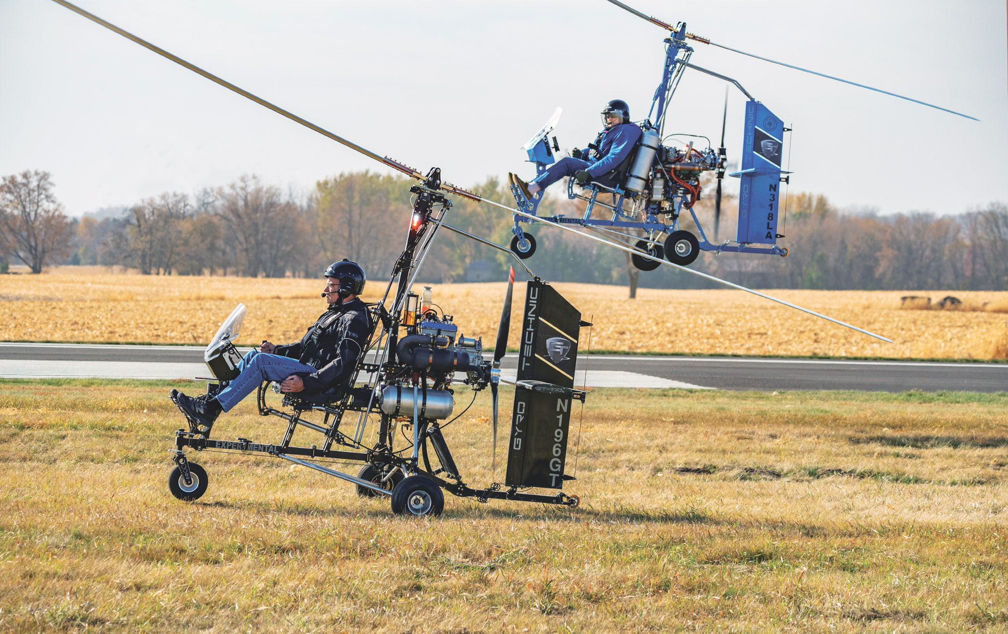
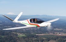
And then I came upon Gyro Technic at Sun ’n Fun in 2024. I was impressed beyond measure with the engineering, fit, and finish of the company’s machines, and power wouldn’t be a problem as their VX-2 model sports a 100-hp Rotax 912. Equally important, all the expert pilots I spoke with thought Gyro Technic made a great flying machine. To top things off, the company also offered builder’s assistance, something that would allow me to try my hand at putting together a flying machine. You can assemble a Gyro Technic at home, but if you’re a novice builder like me you might find the expert help invaluable, if not absolutely necessary! I contacted Gyro Technic’s owner, Denis Schoemaker, to get more details and within six months I was in Kasota, Minnesota, to build my dream. I could have started on my gyro sooner, but I wanted to complete the machine in late April when the weather would be more comfortable for open-cockpit flying.
An Improved Bensen-Type Gyro
Gyro Technic grew out of Schoemaker’s extensive background in robotics, tooling, and custom automation and his curiosity about gyroplanes. Using computer design and automation, he set out to build a dynamically stable gyroplane utilizing centerline thrust and a generously sized horizontal stabilizer and rudder. “By aligning the thrust vectors through the gyro’s center of gravity you eliminate unwanted attitude changes with changes in propeller or rotor thrust,” Schoemaker explains. Additionally, the open frame design eliminates the large side surface areas that enclosed gyros have, which cause unwanted yaw forces during uncoordinated turns. “I don’t even have a yaw string on my gyro because it’s not an issue. The small profile is also why my open cockpit gyros don’t need a long tail boom to counteract yaw.”
The company makes two models—the VX-1 and VX-2. Both are single-seaters, with the VX-2 featuring a four-stroke Rotax 912 and the VX-1 sporting either a Rotax or Simonini two-stroke. The two machines are similar in appearance and construction, use many of the same parts, and vary primarily to accommodate the differences between the two- and four-stroke engines. The VX-1 is about 50 pounds lighter than the VX-2. That makes it a more nimble machine (You can get the specifications of the machines at www.gyrotechnic.com.) “The VX-1’s lighter weight makes it very agile, but its two-stroke engine isn’t as fuel efficient as the four-stroke in the VX-2 so you can’t fly as long. It is less expensive though by about $15,000.”

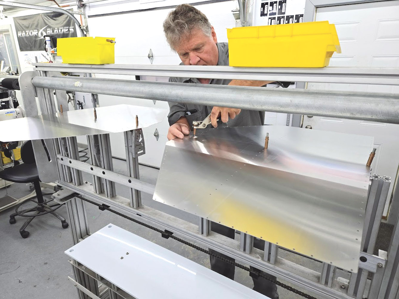
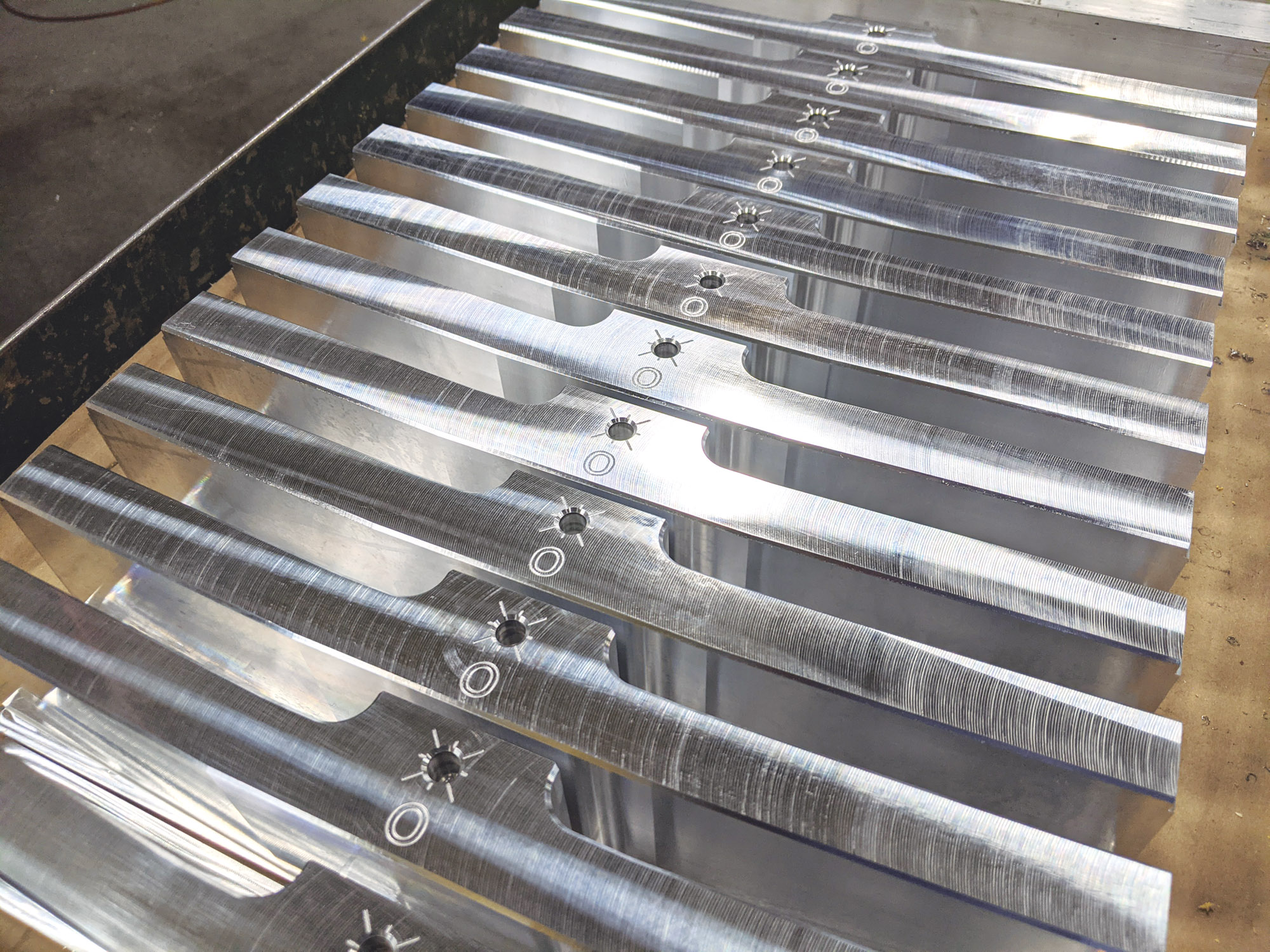
The VX-1 and VX-2 use the same rotor head and hubs. The blades on the VX-2 are 1 foot larger in diameter, and if there’s any magic in Gyro Technic’s machines it’s probably here in the blades. The company manufactures its blades in Minnesota, and its work represents American craftsmanship and engineering at its finest. Gyro Technic’s “Razor Blades” are made from machined, formed, and bonded aluminum, and they are incredibly strong and precise.
The blades are designed around a NACA 8H12 profile and have a built-in reflex and non-linear twist. Heat curing of the blades in a specially designed oven Gyro Technic put together ensures perfect adhesion and alignment of the materials. (You can see an excellent video about how a set of Razor Blades are made here: tinyurl.com/razorgyro.) The company’s hub setup is also unique in that it allows for simple tracking adjustment of the blades via a setscrew instead of adding clumsy and less precise shimming.

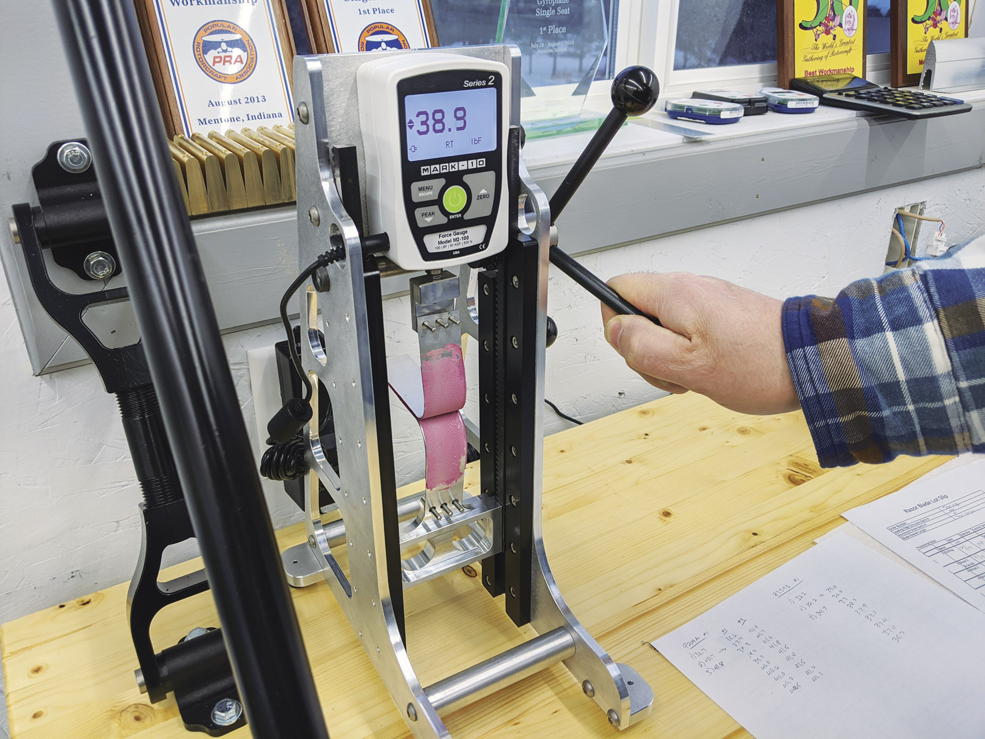
Gyro “stick-shake,” vibration and movement of the control stick during flight, due primarily to unbalanced or poorly tracking blades, is minimized with a set of Razors. The blades fly so well that Gyro Technic has established a market selling replacement systems for other companies’ gyros. The blades recently were awarded a “Section T” approval for use in the U.K. “I developed these blades not only for our own machines, but for legacy gyros too,” said Schoemaker. “We’re shipping them out all over the world.”
Gyro Technic’s kits start at just under $25,000 sans engine and avionics. As for a motor and instruments, you can go for simplicity or the latest and greatest like I did. In addition to the Rotax 912 iS, I ordered the Kanardia Nesis III and Emsis glass panels for flight and engine monitoring. I also added navigation, strobe, and landing lights to go with a radio and transponder. I regularly fly in somewhat crowded airspace and I need to be seen and heard as much as possible. At around $75,000 my build is on the high end, but this is an Experimental aircraft so you’re free to add or subtract items to fit your budget. A VX-1 can be built for as little as $50,000. The company will assist you in getting it all working together no matter your choices. Gyro Technic, however, does recommend certain engines and avionics packages to simplify and speed along the building process.
Week 1: Arrival, Skinning the Tail, and Building the Frame
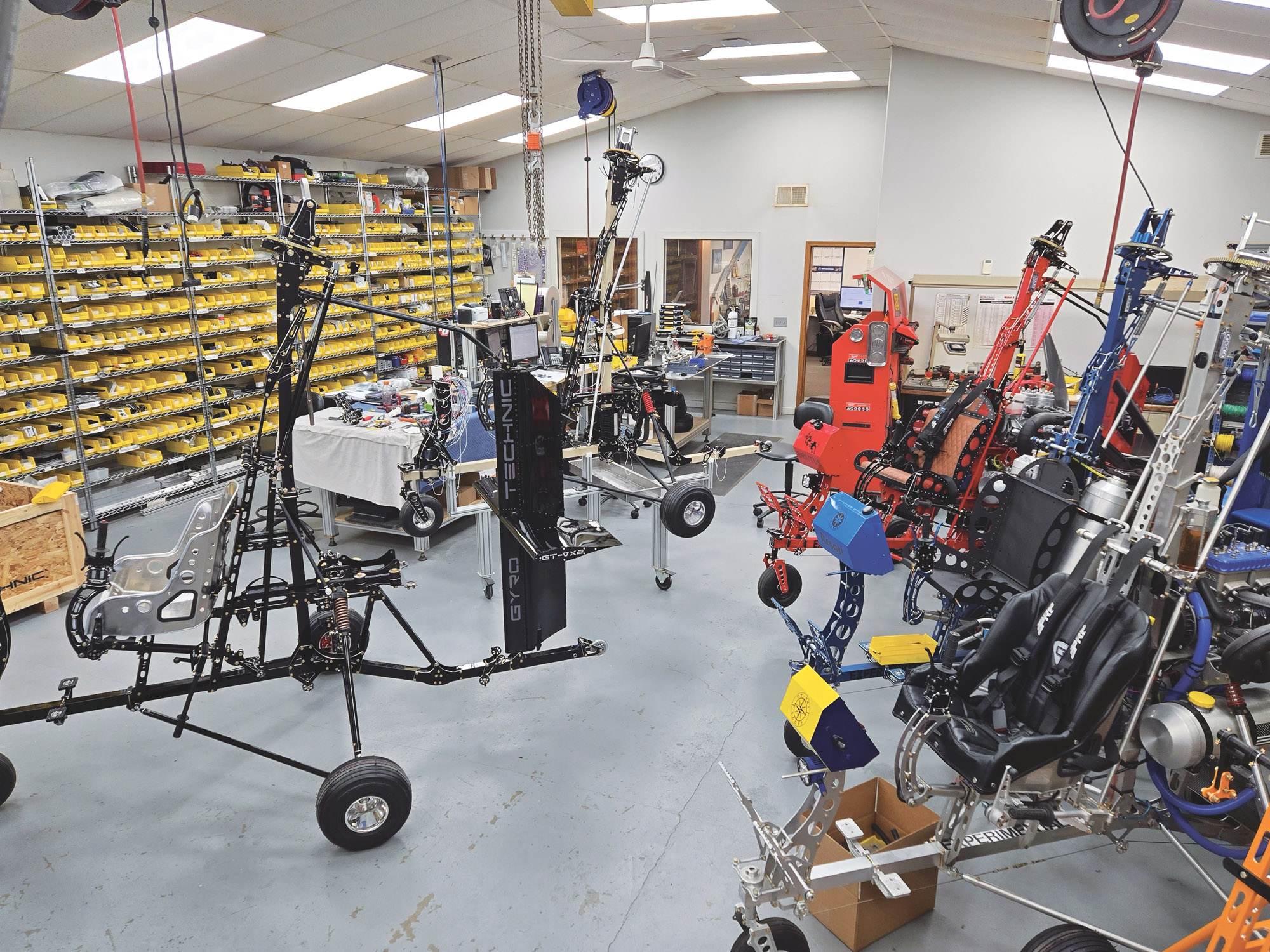
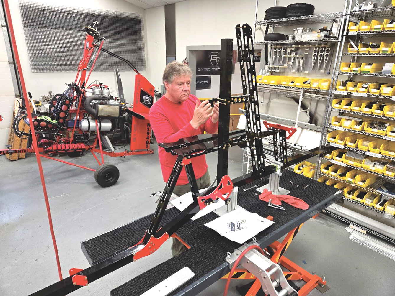
I arrived at Gyro Technic’s Minnesota manufacturing facility late in the afternoon of Sunday, April 13. Schoemaker helped me get settled into the bedroom and common area he has for housing builders. The bed, desk, shower, and cooking area were clean and cozy and more than adequate for my needs—just enough “me-space,” and all of it literally a few steps away from the shop where I’d be working. Schoemaker gave me a tour of the facility and then let me spend the rest of the evening resting from my two-day, 22-hour drive from New Hampshire.

The Gyro Technic crew was ready for me first thing Monday morning. Apart from Schoemaker, I’d also be working with the company’s three other employees: Grant Robertson, a former master auto mechanic and all-around tool whiz, for general assembly; Mike Petersen, an electrical engineer, for avionics and wiring; and machinist Mike Schaffer for any additional fabrication work I might need. All three would soon prove to be especially capable, helpful, and pleasant instructors/assistants. The shop is a joy to work in—fully equipped, well-lit, and comfortable—a good thing, as I would be spending the next few weeks working nine hours a day on my gyro with these people in this environment.
The first step of the build was to assemble my gyro’s horizontal stabilizer, vertical leading edge, and rudder. Schoemaker explained to me that I’d be bending pieces of precut and drilled aluminum sheet around prefabricated aluminum ribs and then riveting things in place. I have very little formal training in metal work, and if it weren’t for having watched a YouTube video a previous customer had made about their build at Gyro Technic I would have been a little nervous about doing such work. Metal shaping can be difficult and takes considerable time to master. The video, however, clued me in on a special machine Gyro Technic developed to assist in this stage of the process.
The machine fixes the stabilizer, leading edge, and rudder ribs in place as its rollers follow a set of guides and bend aluminum skins over both sides of the ribs at the same time. This forms the airfoil shapes perfectly, and you only need to insert Clecos into the predrilled holes as the machine’s rollers progress downward and bend the sheeting. You insert a few rivets here and there along the way with a pneumatic gun to keep things in place until you have all the necessary Clecos installed. The parts are then removed and set on a bench so you can permanently rivet everything together. Pneumatic rivet guns are a godsend! I put in more than 600 rivets in a few hours. My hands were feeling the strain of manually inserting and removing Clecos. I can’t imagine having to do that much riveting by hand.
The next step was to rivet together the gyro’s instrument pod. After spending the morning and the first part of the afternoon on the tail, putting together a simple box was child’s play, especially with the documentation Gyro Technic provides. The company’s parts and assembly diagrams are beautifully done and easy to follow. Every step of the way there was a diagram to show how things fit together. Looking at the illustrations brought back memories of putting together plastic models as a kid. Once I had the pod completed, the box and tail assemblies were off for powder coating. That was pretty much it for day one. I’d start on the frame the next day.
The frame of a Bensen-type gyro is the shape of an upside down “T.” The mast, fore, and aft sections of the “T” are bolted together with aluminum gussets. The assembly was Erector Set-simple, and by the end of the second day the skeleton of my gyro was well along. All the holes in the frame and gussets are predrilled, but almost all of them need reaming to remove excess paint, powder coating, or anodizing. Then, it’s just a matter of adding bolts, washers, and nuts.
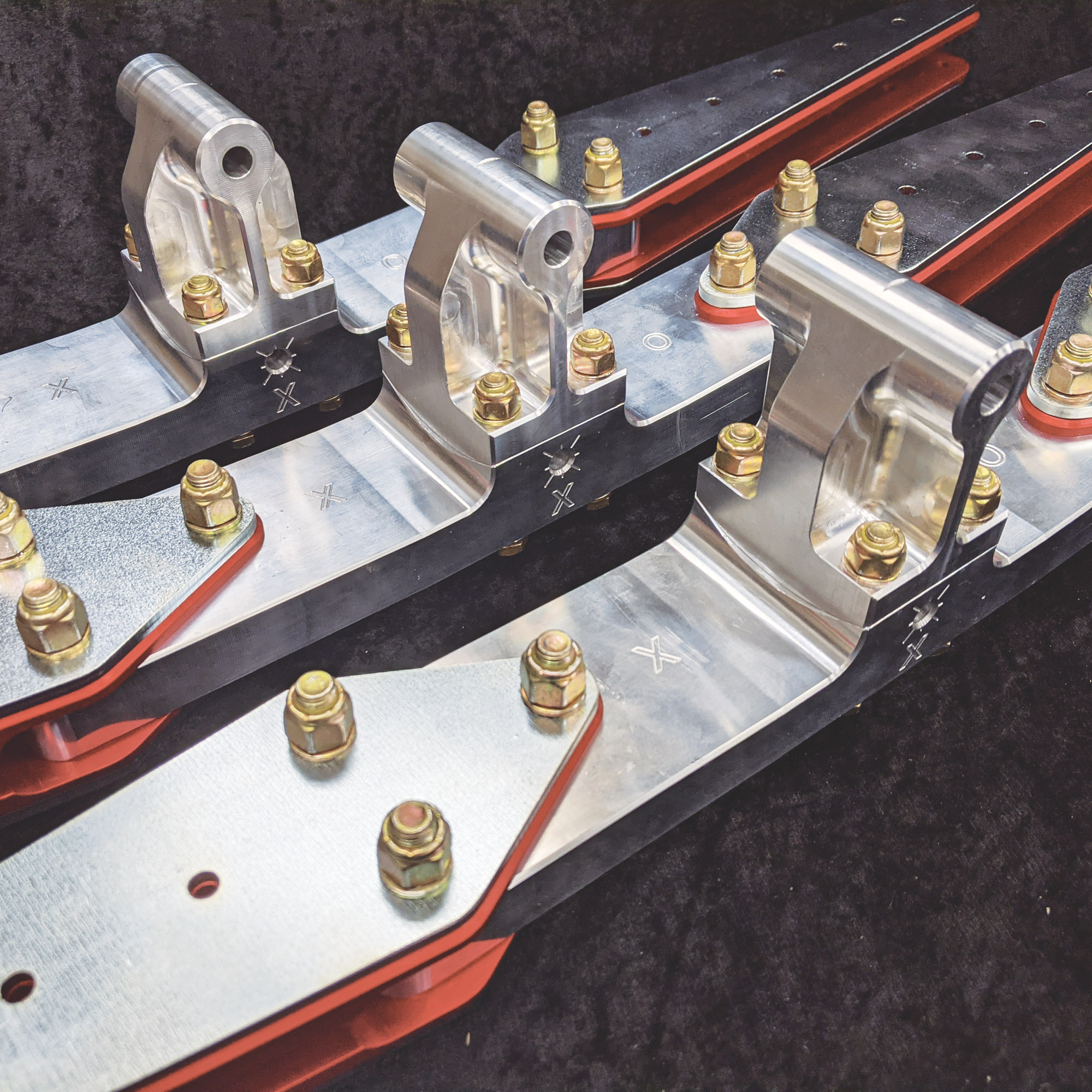
Part by part the gyro was coming together as I began to bolt pieces to the frame, including the landing gear attachment points, nosewheel, engine mount, and the seat frame assembly, among many others. I can’t describe how exciting it was to see a gyro emerge from a pile of parts. But I had a lot more work yet to do. A lot more work! That will be covered in Part 2 of this article.


")


Thanks for sharing your build experience, Mark! I especially appreciate your reassurance as I’m planning a similar adventure for this coming fall.
I’ve never built an experimental aircraft of any kind, so even though I’ve read AC 90-89, I’m a bit overwhelmed by trying to figure out the required paperwork.
Looking forward to your subsequent article(s)!
Comments are closed.