Many aircraft use screws to attach the wingtips to the wing. On most RVs, for example, approximately 40 AN507-6R6 screws are required per wingtip. I’ve noticed that on nicely painted airplanes that use screws to attach the wingtips, the screws often look stripped out and there is puckering of the wingskin between the attachment screws. For better appearance, and to make it easier to remove the wingtips, I decided to use piano hinge on my RV-7 to mount the tips to the wings.
Required parts are two 6-foot long pieces of 1.5-inch wide, .040-inch thick MS20257P4-6 piano hinge (Aircraft Spruce Part #03-00050-6), and two 6-foot long pieces of 1.25-inch wide, .040-inch thick MS20257P3-6 piano hinge (Aircraft Spruce Part #03-00049-6). The reason I used two different open widths of hinges is because I did not want to see the eyelets of the hinge where the wing and wingtip meet. The thicker hinge is mounted to the wing side, and the thinner hinge is mounted to the wingtip.
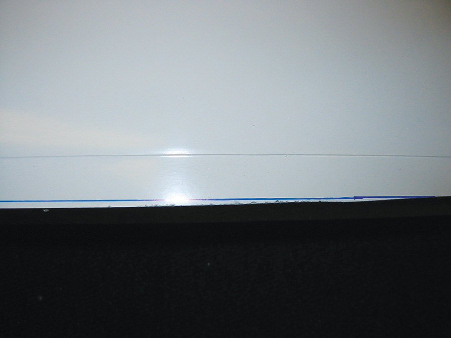
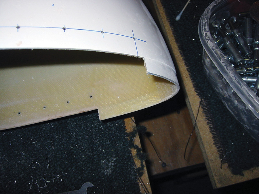
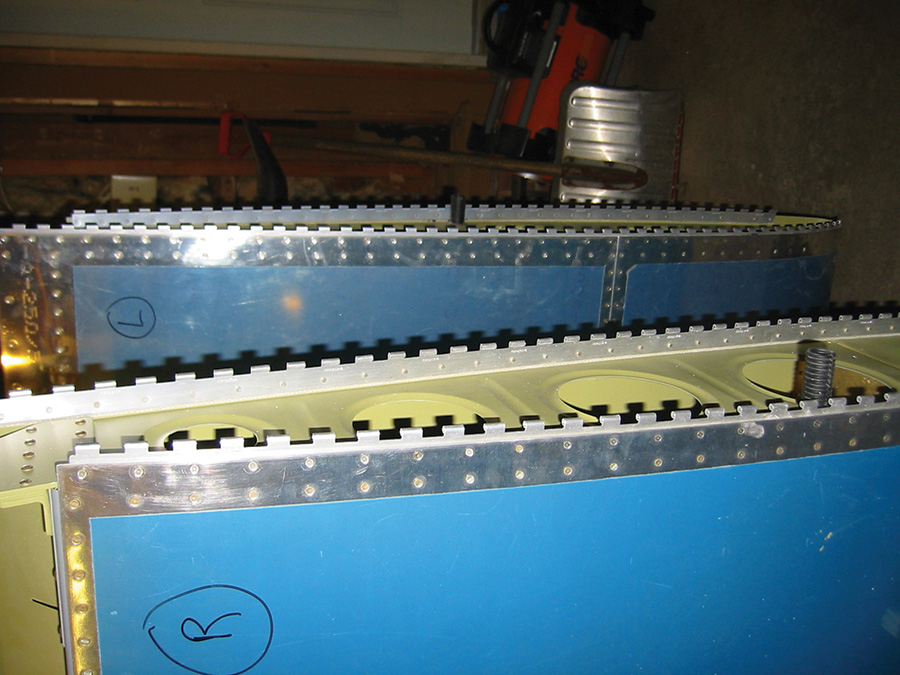
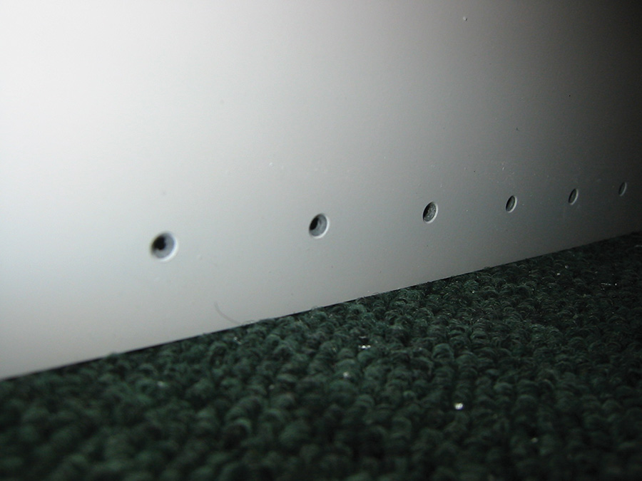
1. Trim the wingtip so it fits onto the wing. This wingtip flange was too wide, causing it to not seat flush with the end of the aluminum skin. The picture shows how the thickness of the flange varied along the length of the wingtip.
2. Don’t worry if the trailing edge of the wingtip is longer than the aileron. This can be fixed later by chopping off the wingtip’s trailing edge. The important thing is the general alignment of the wingtip. Make sure the aileron is centered and the trailing edge of the wingtip is aligned perfectly with the trailing edge of the aileron.
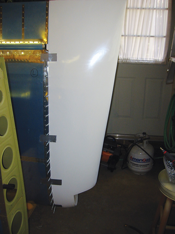
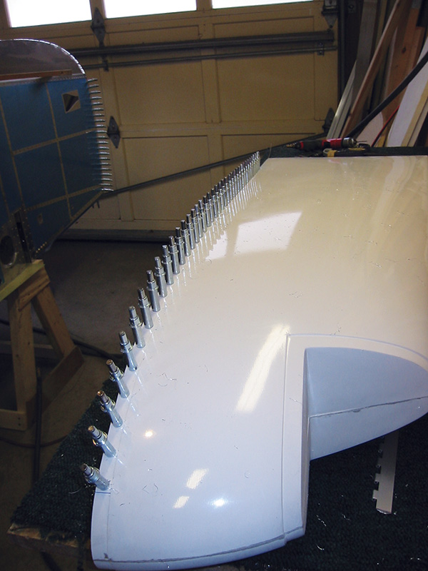
3. Tape the wingtip to the wing with duct tape and use the pre-drilled #40 holes on the outboard end of the wing to drill into the wingtip flange.
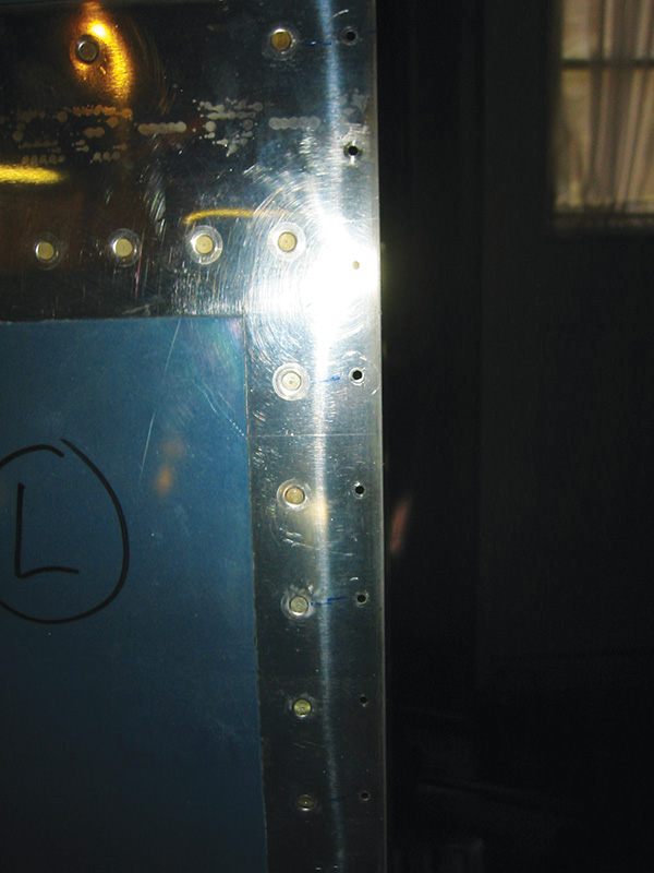
4. The default hole spacing for the #6 screws is too wide for a line of rivets. Use a rivet spanner to drill a new hole in between the existing holes on the outboard edge of the wingskin.
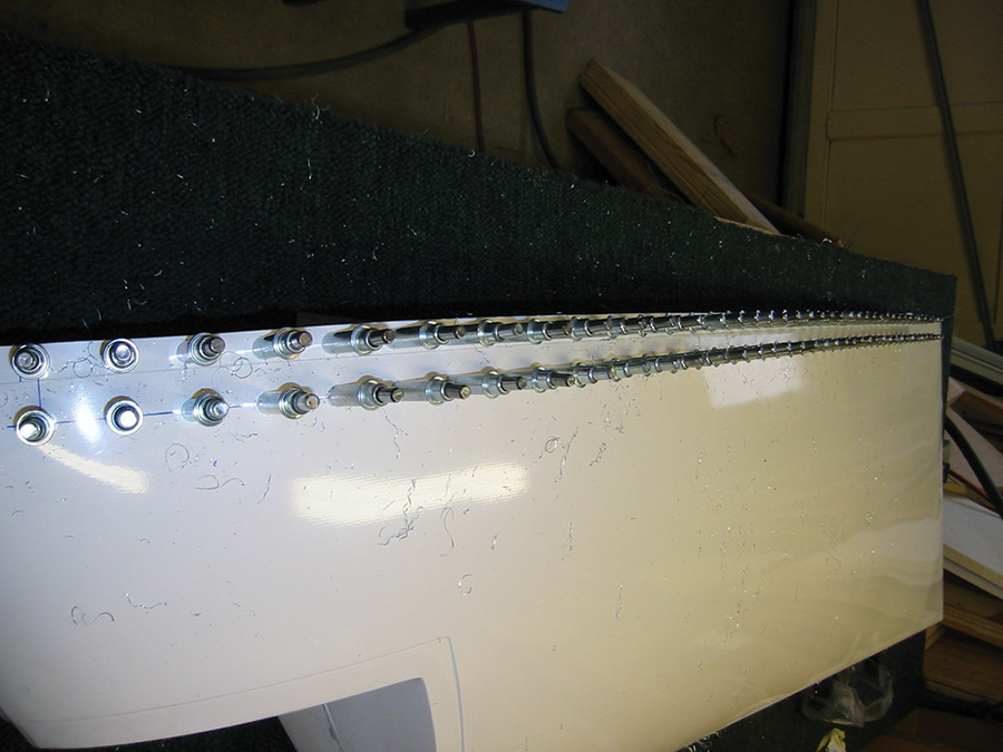
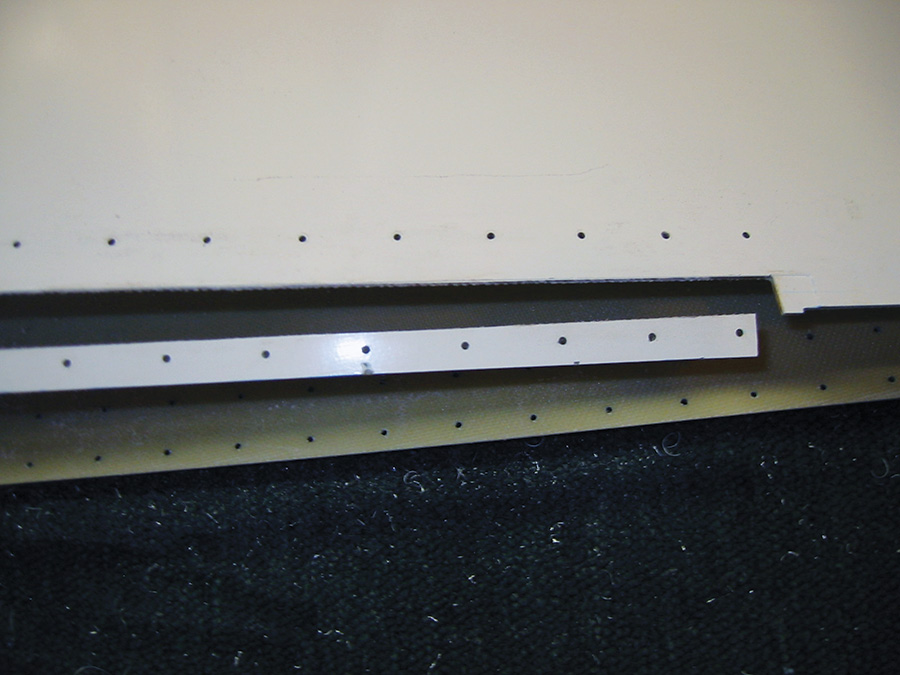
5. Now that the wingtip has been drilled to the wing, the wider P4 hinge material can be drilled to the wingtip using the holes drilled in steps 3 and 4. Use Clecoes in every hole to keep things tight.
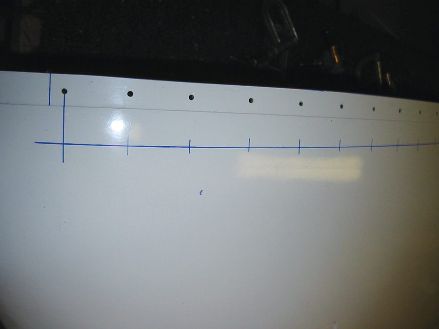
6. Next, drill the thinner P3 hinge to the wingtip. To do this, mark where the rivet line should be by using the existing wing-side holes in the wingtip flange as a guide.
7. Using the marks made in the previous step, backdrill the P3 hinge.
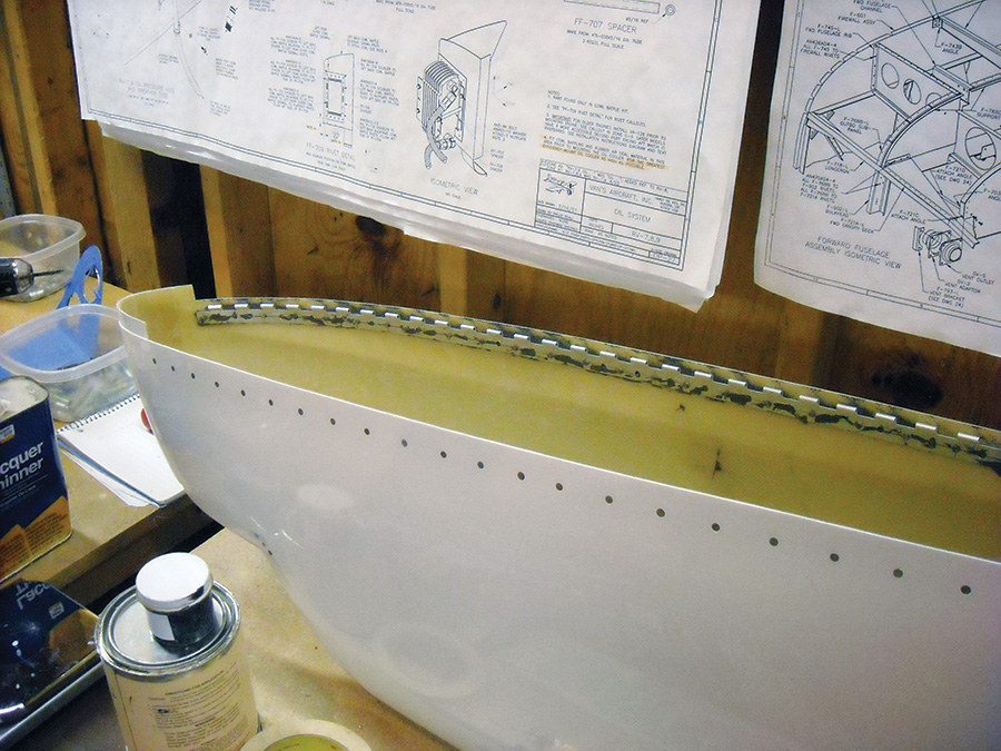
8. With all of the holes drilled in the hinges, it is time to remove the flange from the wingtip. This flange will be used as a spacer on the wing-side so the wing and wingtip are completely flush. Don’t cut the entire flange off—just the portion that has the hinge overlapping it. Keep the leading edge flange attached to the wingtip.
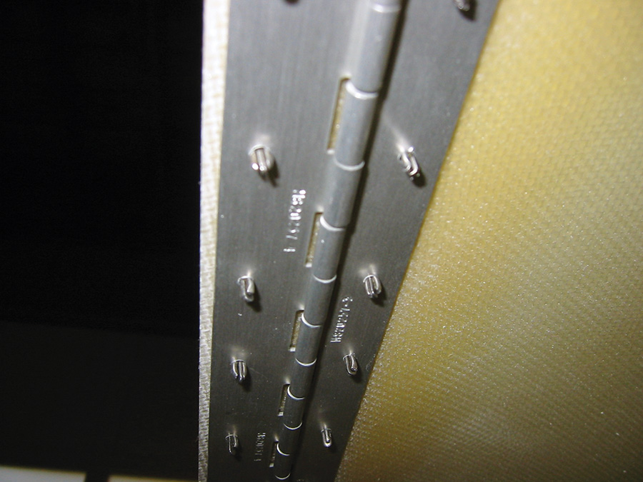
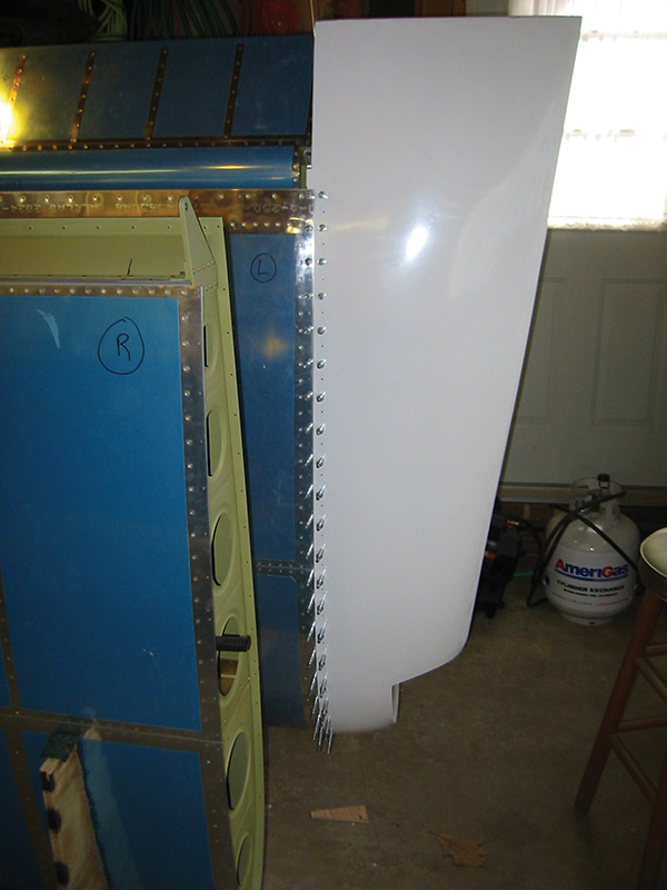
9. Do a test fit. Here you can see how the eyelets of the piano hinge won’t be visible in the seam between the wing and wingtip.
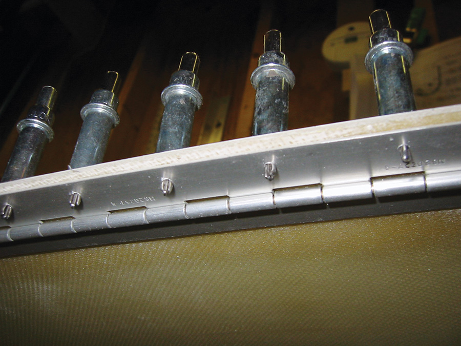
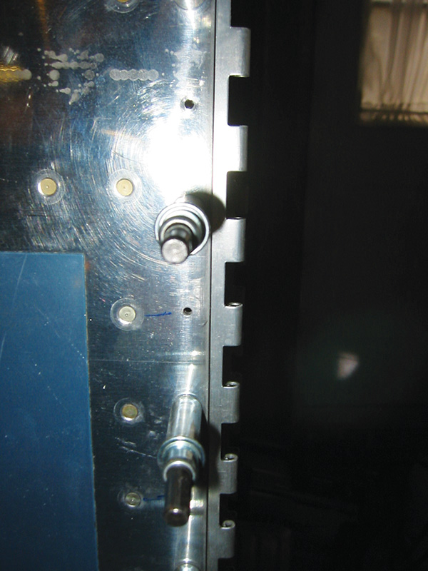
10. In the first photo above, notice how the flange from the wingtip acts as a spacer between the P4 hinge and the wingtip skin. It’s now time for a test fit (bottom photo). If the hinge pins don’t slide easily through the eyelets of the hinge, use BoeLube or some sort of wax as a lubricant. You can also slightly increase the diameter of the hinge eyelets. One way to do this is to take a scrap piece of hinge and heat up one side of it with a torch. Once hot, use a hammer to slightly flatten the end, then chuck the other end of the hinge pin into a drill, causing the pin to act as a reamer.
11. Permanently attach the wing side of the hinge to the wing. Dimple the holes in the skin and countersink the fiberglass flange from the wingtip.
12. For the wingtip P3 hinge to be attached, the wingtip #40 holes need to be countersunk. Use Pro-Seal to bond the wingtip hinge to the wingtip since sometimes rivets can pull out of fiberglass.
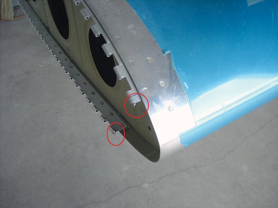
13. In order to prevent the hinge pins from sliding too far forward, install #4 stainless steel screws in the eyelets of the wing-side hinges.
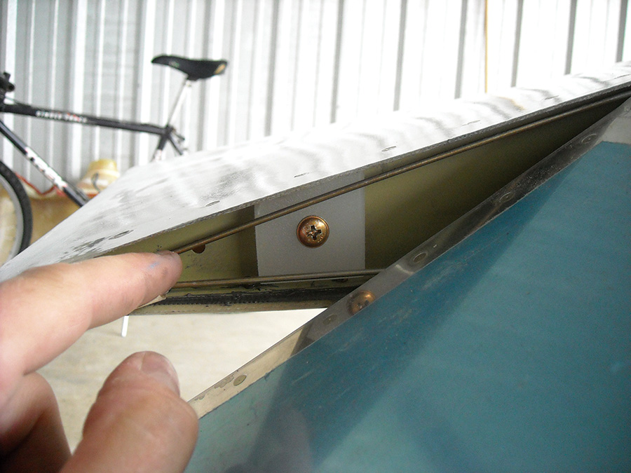
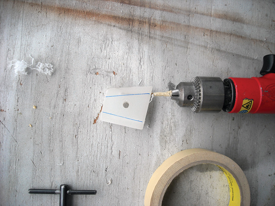
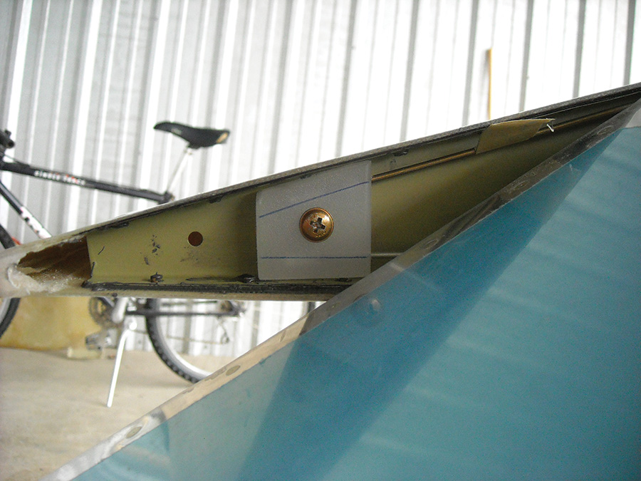
14. The final step is to secure the hinge pins to the wingtip rib. Cut a small piece of old plastic cutting board to the contour of the wingtip rib, drill a #12 hole in the middle, and attach the screw to a nut plate. Place the plastic block in the wingtip rib to get an idea where the pins would settle in the block.
15. Mark the block with a marker to show where the pins will enter into the block. Using a #40 bit, drill two holes into the block. Do not drill all of the way through because you do not want the pins to vibrate out and possibly interfere with the aileron.
16. The finished product. This modification has worked perfectly during the 3 years and 200 hours the author has flown his RV-7.







Just a thought…. If the screw holding the plastic block were to come loose could it jam the aileron?