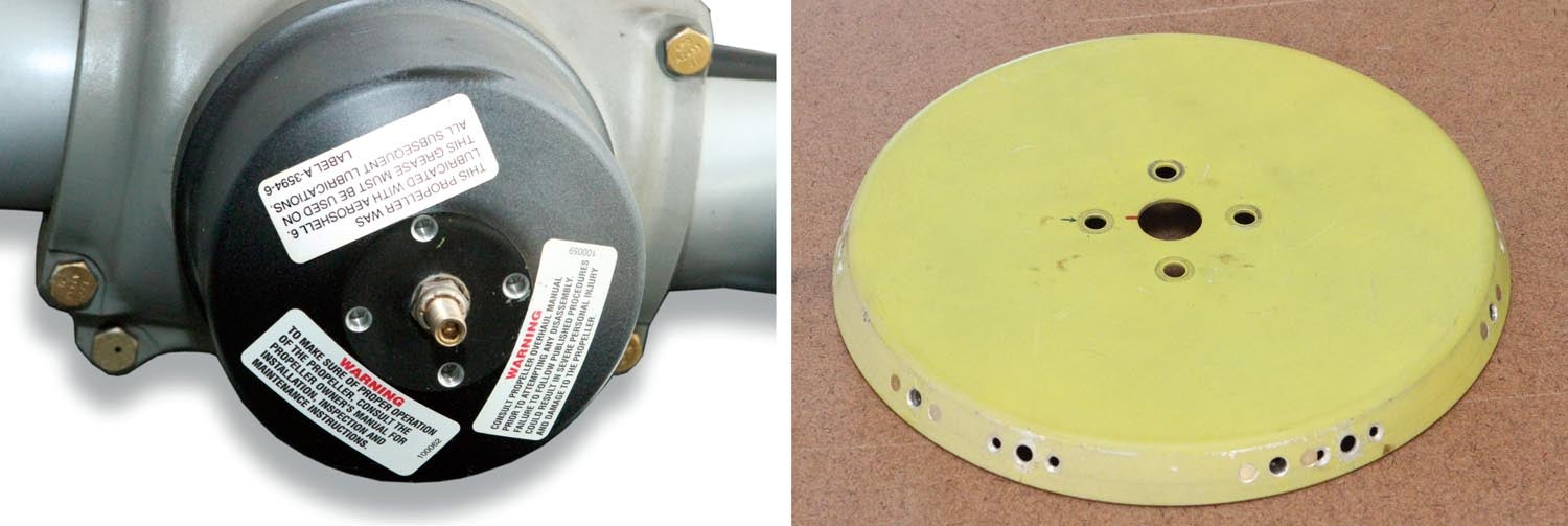
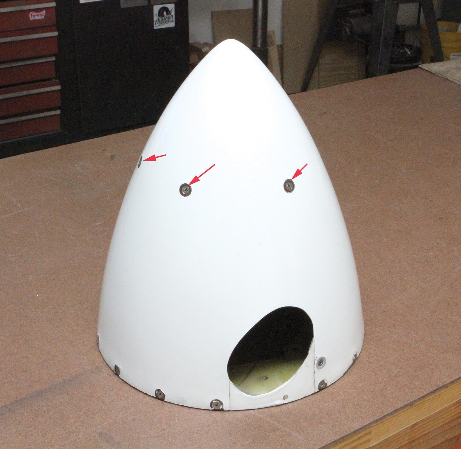
Spinner woes were the topic of midsummer musings on Van’s Air Force this year. Specifically, Bill from Virginia commented how, after getting his Hartzell prop hub back from an eddy current inspection (ECI) and installation of new seals, the spinner mounting holes on the S-603 forward bulkhead no longer lined up with the corresponding holes on the spinner. (For more information on this ECI inspection AD, refer to FAA document number E9-25290.)
As is typically the case with VAF, which is, without a doubt, the mother of all portals for homebuilders, the issue was discussed and solutions were posted in fairly rapid succession. Within a couple of days Bill had the answers he was looking for and then some.
KITPLANES® Editor at Large Paul Dye noted, “Unfortunately, that’s the way it works with a Hartzell prop—the black ‘dome’ never goes back on with the same exact clocking. (I don’t know how the prop shop thinks they could have done it.) What you hope for is that it will be far enough off that you can reuse the forward bulkhead by just drilling new holes and putting on new nut plates. What’s frustrating is when it’s just a degree or two off and the holes for new and old interfere.”
Next up was Tim from Peoria, who added, “Just had mine resealed this spring. My alignment was changed, but not by much. I just took a file and slotted the four bolt holes. If you do a search, you should come up with a thread on VAF discussing this. (Perhaps your alignment is too far off for slotting and new holes will need to be drilled.)”
Don from Louisiana offered, “This one is pretty easy. The prop shop has to torque the dome (pressure cylinder) on and it ends up where it ends up. Usually it’s a little more righty-tighty from where it was before. If off by a little, I slot the holes; if a lot just move the nut plates. Nothing wrong with installing a new bulkhead, but it’s not necessary.”
But it was what Keith from Georgia posted that caught the eye of the home shop machinist: “Just got mine back from the prop shop. Six-year service. Looks brand new. Was aware that the (bulkhead/spinner) holes would need to be ‘adjusted.’ Prop shop isn’t going to be concerned about those holes lining up with your spinner. Their concern is proper torque on reassembly, so I’m told. And seems much more important. Friend with a milling machine, offered to do the relocating of the holes to exactly fit. About half an hour. Bought him lunch. Good to have talented friends. Tim’s file method, above, would work. But this is a little more precise.”
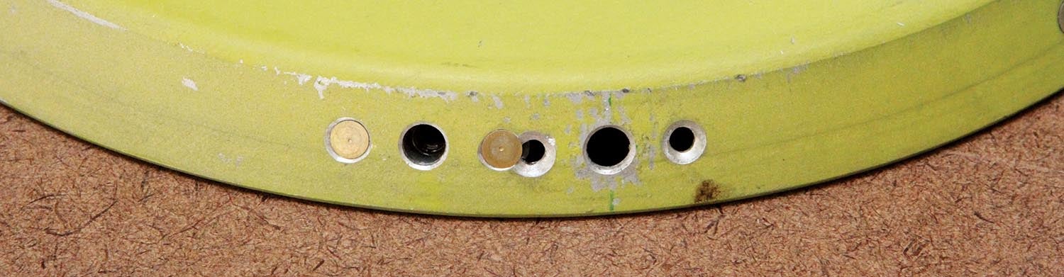
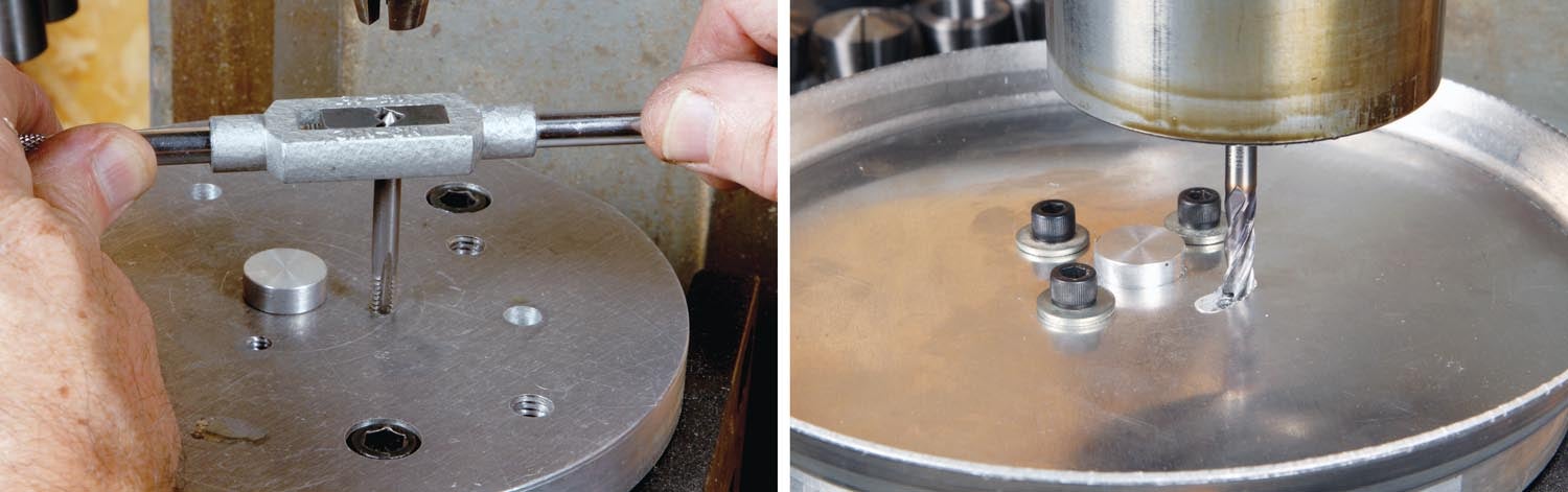
Keith included two photos with his post. One of his spinner bulkhead indeed being modified on a milling machine and the other was of the bulkhead after machining, showing how the holes had been slotted. What was missing in the description was how Keith’s very clever friend (a friend indeed!) made the slots, which were concentric arcs, using a rotary table. That one photo, as they say, was worth a thousand words!
When Paul saw Keith’s photos, the genesis for this month’s column began to gel. Could slotting the bulkhead eliminate the need to redrill and reposition the nut plates?
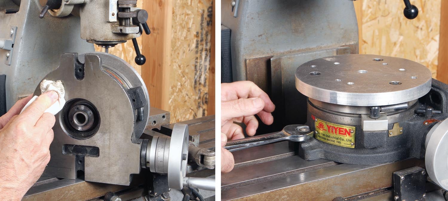
Regular readers may remember a brief introduction to the rotary table back in the August 2022 issue. As mentioned then, rotary tables are indispensable for milling arcs and circles and for indexing hole patterns or milling teeth for sprockets or gears. While the need for rotary tables has been eliminated by CNC machines in manufacturing, in the home shop, rotary tables play a vital roll when it comes to a job like this.
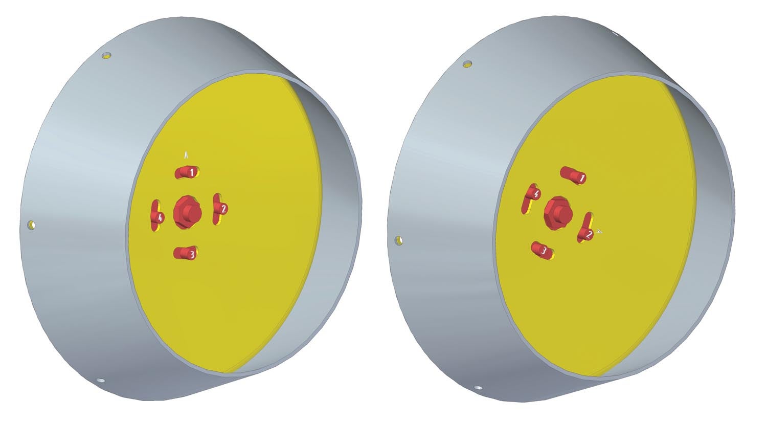
The first step was to play with some geometry to see if there was a slot solution that could completely eliminate the need to redrill and reposition nut plates. Rather than befuddle my brain with a bunch of sine and cosine calculations, I used Solid Edge to model the three key components of the assembly: the cylinder housing with bolt holes, the bulkhead and a segment of the spinner with the recommended six mounting holes. Then using the assembly feature in Solid Edge, I combined the components and, by manipulating the hub clocking, I was able to verify that slots having 30° of arc were sufficient to accommodate any possible hub position.
EAA members may download a free version of Solid Edge Community Edition for non-commercial use.

No 3D CAD software? You could also do the same thing by sketching the components and making cutouts to rotate the “parts” around.
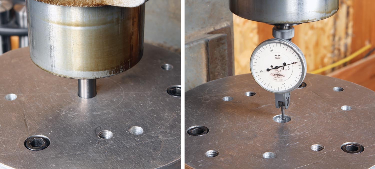
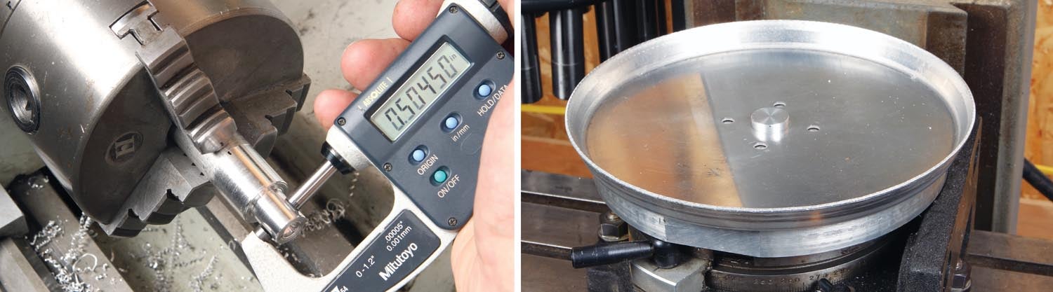
With the theoretical proof in hand, it was out to the shop to set up and make some chips!


I do not have a CS prop however (as an engineer) it amazes me that the prop shop doesn’t have a jig to hold the black ‘dome’ in place when it is reinstalled. The “clocking” position should be noted before disassembly so the “dome” can be reinstalled at the same angle on reassembly. I’m sure this is not just a VAF issue.
Bob, what method did you use to add the part number and modification markings when you were done?
I used a “13-character alpha-numeric stamp” with StazOn ink to mark the part. number and date. You can reado more about this in my column “Trail of Crumbs” https://www.kitplanes.com/home-shop-machinist-43/
Comments are closed.