Back in November 1999, I sadly consigned my old battery eating “buzz box,” a WW-II 1940s-era mechanical doorbell-ringer magneto timer, to that big buzz box dumpster in the sky. In its place, I brought forth one of those newfangled integrated-circuit, low-power, electronic audio buzzers with optical LED display powered by a few small AA cells. That prototype magneto timer has well and faithfully served these past 22 years and several hundred of my annuals and Experimental homebuilt condition inspections.

As with all things, I have always been aware of some shortcomings in my original design. The main problem was a mode where the entire box was quiet and unlit. Was there a power disconnect or was this a normal response? Unfortunately, you couldn’t tell without moving the prop to un-time the engine. And, is an external battery necessary, or can I run this from my aircraft battery?
To answer these questions it is necessary to understand just a little bit about the internals of a magneto. The simplistic explanation of a magneto is that there is a large coil of wire with several thousand turns mounted in a cavity with a whirring magnet in the middle of that coil. Now, it is the function of a coil of wire with a spinning magnet to keep the current in the coil constant. If, for whatever reason, the current in the magneto load is changed, that coil acts in a way to keep the current the same by changing the voltage in the new load to make this current the same. In particular, if the load is completely removed, the coil voltage will rise to a really-huge value in a vain effort to keep that current constant. That huge voltage will be more than sufficient to jump a small gap in a spark plug specifically designed to let that spark happen. Load opens, voltage jumps to tens of thousands of volts, jumps the 0.018-inch spark plug gap, igniting that 15% mixture of gasoline/85% air, which explodes on the piston, rotating the crank, twisting the propeller, and repeating this 20 times a second at 2400 engine rpm.
Just as an aside, a magneto is a way of converting mechanical energy (rotating magnet) directly into electrical energy to spark the engine. This technology is a descendent of elderly 1920s-era Ford farm tractor engines. This does away with the need of any other systems to keep the engine turning. Later technology (1930s) depended on mechanical engine-driven generators to charge an electrical battery to supply that current into an ignition coil, through “points” to break that current and thus spark the engine into life—today’s technology. And, as usual, there are good arguments on both sides as to which is the more reliable, less weight, and “best” way to do ignition. Magneto is fail-safe (but mechanical), generator is more efficient and more reliable (but electrical). Toss your coin.
But I digress. I wanted to take that 1999 mag time design and bring it screaming and kicking into the current millennium. I think I succeeded in most respects but was fascinated with one failure.
The failure was the search for a better heart for the design, the “chip” operational amplifier LM324.
There are designs that are considered classics of time. The DC-3 and the 737. The 1957 Chevy and 1953 Corvette. The Vari-EZ and the B-52(x). The Mona Lisa and The Thinker. And now the LM324 integrated circuit.
I tried the later “improvements” like the field-effect transistor version LF353 and the CMOS (complementary metal oxide semiconductor) LMC6024. They had a hard time driving the LEDs and the beeper at the same time. They were extremely sensitive to environmental concerns like static electricity and varying parameters with being inside a refrigerated tin shed hangar in January and tin shed oven in July. Moreover, they are between five and 10 times the price of the venerable 324.
The clear winner was the elderly standard LM324, first introduced by National Semiconductor in 1972, at the astounding (at the time) price tag extrapolated to $17.50 in 2021 dollars. Today, that exact same device is widely available for about 50 cents, 2021 pricing.
Here are some of the changes and improvements from our KITPLANES® 1999 design:
- The mag timer will run from a 9-volt battery, the 12-volt aircraft system or the 12-volt HOG supply.
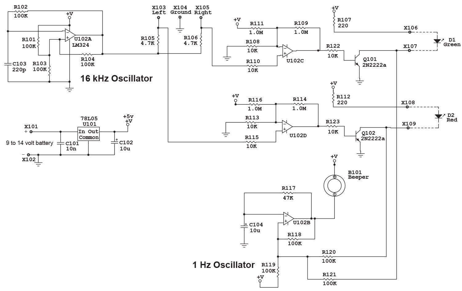
- The unregulated AA-cell battery supply was replaced with an electronic voltage regulator to make the operation virtually impervious to power supply battery voltage variations.
- The voltage spikes expected from the breaker points were such that we used Zener diodes (three of them) in the original design. Later investigation showed the Zeners were determined not to be necessary due to the incredibly robust design on both inputs and outputs of the LM324.
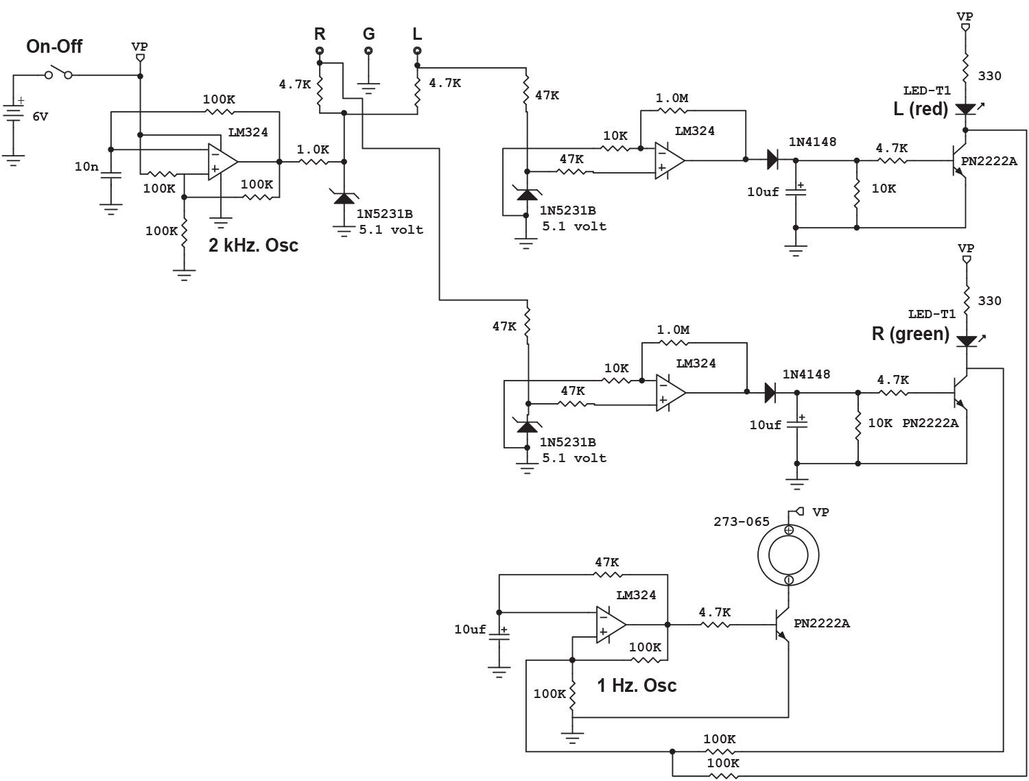
- The driver oscillator is now 16 kHz, up from 2 kHz in the original design. This makes both the LEDs and the beeper “chirp” in one mode (open points) and truly beep and flash in the closed-points mode.
- The mechanical buzzer from Radio Shack (a current hog as well as “The Shack” being out of business) was replaced with an electronic low-current beeper with a much more penetrating tone.
- All of the parts are now truly “garden-variety” devices that you can get from dozens of sources. The one exception is the little beeper that is available from All Electronics, SparkFun, Amazon and half a dozen more sources.
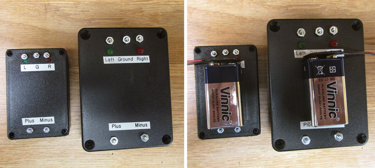
- To bring the price down, eliminate the On/Off switch in favor of just disconnecting the battery, and use holes in the chassis to mount the LEDs. To provide power supply connections for less than a dime, use a plastic chassis and simple screw-nut fasteners.
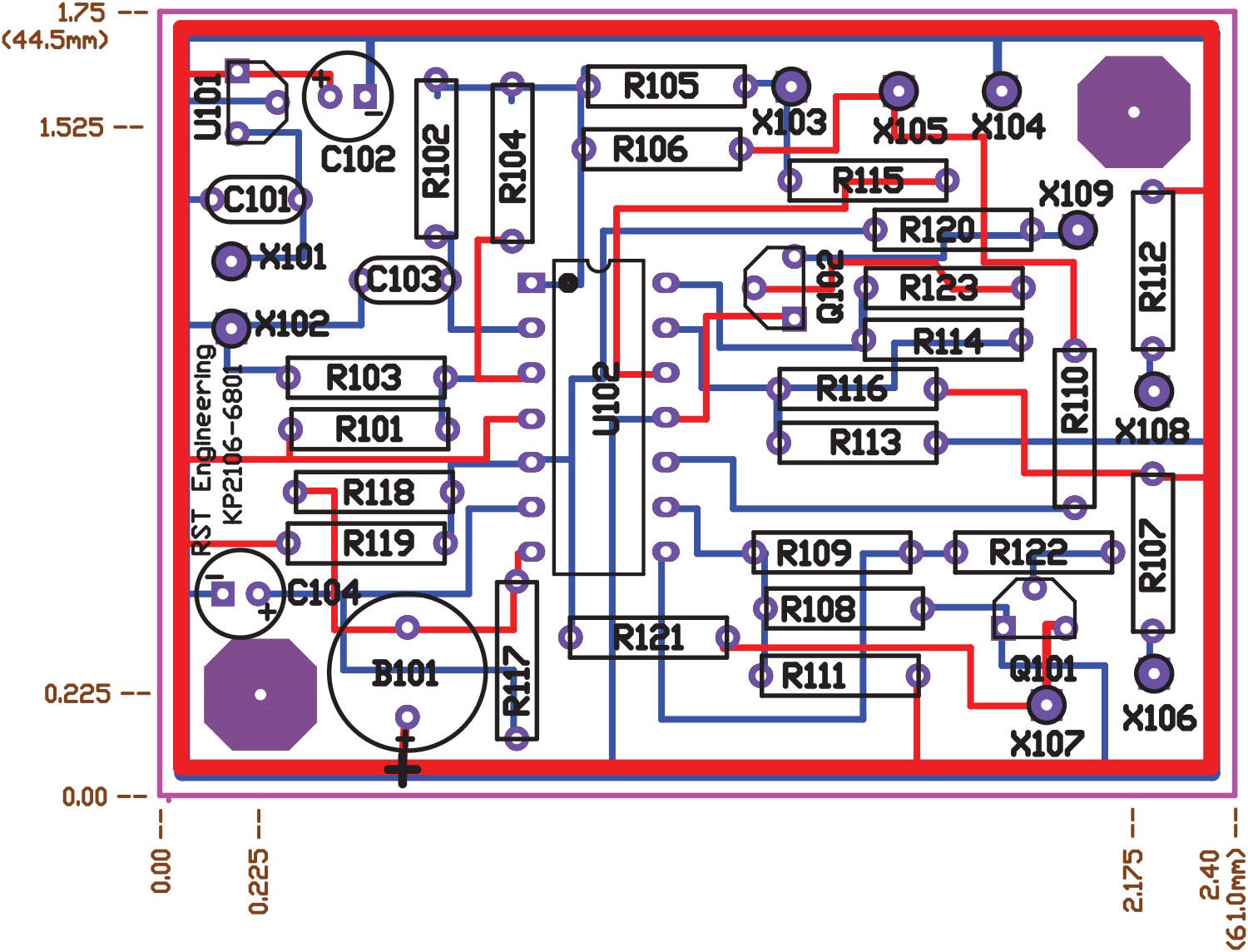
- Finally, as will be true in all of my hardware designs, there is a full set of manufacturing files for the PC board that goes along with this project at www.rstengineering.com.
As I write this in the middle of February, it is a beautiful pre-spring 60° day with sunshine overflowing the sky. That is sandwiched in between last week’s snowstorm and next week’s five days of cold rain. I promise, spring is on the way and I’ll get back to the HOG project as soon as I can. But there are some other interesting things we can do until the April showers bring May flowers and I’m not freezing my hiney in the hangar.
I’m not sure I can do all of these, but I’m going to give some of them a try. How about a digital fuel gauge that reads out in gallons (or liters) instead of Empty—Half—Full. Or digital meter indications with a “slosh filter” that shows fuel movements in minutes instead of seconds. Or maybe a couple of “fun” antennas for your home or hangar station: a Yagi gain antenna for distant station reception or a portable dipole collapsible antenna using multi-section whip antenna elements for radio communications Field Day. Or…let your imagination (and your email suggestions) run wild. Write me at jim@rstengineering.com. I don’t promise to violate basic physics principles, but maybe we can bend them a little.
Until then…Stay tuned…


i wanna say big thank you Jim Weir, for share your schematic of buzz box, is working, is very help for me, first i made 16khz circuit but have a problem, if the magneto contact point close or open, the led still light out, so i decide to try made 2khz oscilator but circuit is use 16khz, now is working, opened contact point of magneto, led is lit, and close contact point led light out, thats all, is hard schematic, thank’s again
regard,
yd1lps, Indonesia amateur radio
Comments are closed.