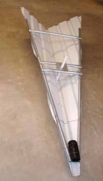
For slow approach speeds and landing on short runways, knowledge of the wind direction is essential. Sometimes my windsock, with its smaller size, can be difficult to see, especially in a slight wind. After studying the problem, I came up with a simple wind tetrahedron that is very sensitive (2 knots) and can easily be seen. Being bright white, 6 feet long and 2.5 feet wide makes it highly visible even from pattern altitude.
Materials You’ll Need
Start with a 6-foot length of white U-panel roofing material (normal width is 38 inches), then add:
- Two 10-foot lengths of three-quarter-inch, thin-wall EMT conduit
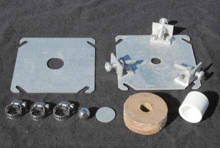
- One 4-inch steel electrical box blank cover (unpunched)
- One 4-inch steel electrical box cover with half-inch knockout (actual hole is about 7/8 inch)
- One 7/8-inch diameter metal disk (knockout) from the electrical box cover
- 1 foot of half-inch PVC pipe
- 1 half-inch PVC cap
- 1 half-inch PVC coupling
- 1 half-inch marble or ball bearing
- A 3-foot length of half-inch steel rod
- 6 feet of 2-inch steel pipe
- Three small hose clamps
- One metal or wood spacer disk with a half-inch hole and outside diameter to fit inside 2-inch pipe
- Three 3/4-inch aluminum angles 1 inch long
- Various sheet metal screws, bolts and nuts.
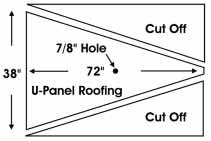
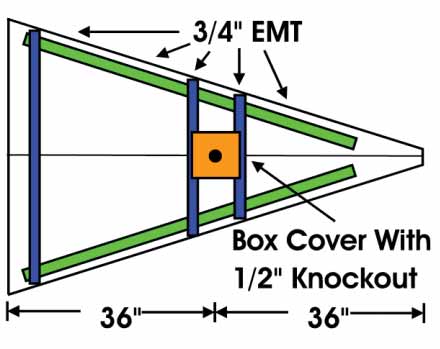
The U-panel will have a ridge down the middle. In the center of the U-panel (36 inches from either end) drill a 7/8-inch hole in the center ridge. From the outer sides of the middle ridge, draw lines to the far corners (Figure 1). The width of the ridge will be the nose of the tetrahedron. Use a metal cutting blade in a circular saw to cut the U-panel to make a triangle. Smooth any rough edges.
Bend the panel at a right angle along each side of the center ridge, keeping the top of the ridge flat. A perfect right angle is not necessary at this point. Cut two pieces of EMT 5 feet long. Screw these to the flat area near the bottom edge of the triangle on each side (Figure 2, Photo 1). Holding the bend to 90, measure the distance at the back of the tetrahedron for the EMT cross brace. Cut an EMT this length. Flatten the EMT ends a bit and screw the cross brace to the side EMT lengths.
With the tetrahedron on its back, use a framing square from the hole in the center ridge to determine where the steel electrical box cover (with half-inch knockout or 7/8-inch hole) will be located. Cut cross EMTs the appropriate length. Flatten the ends of the EMTs, screw the electrical box cover to the EMTs, and then screw the cross EMTs to the side EMTs. Save the half-inch knockout for later.
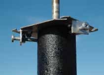
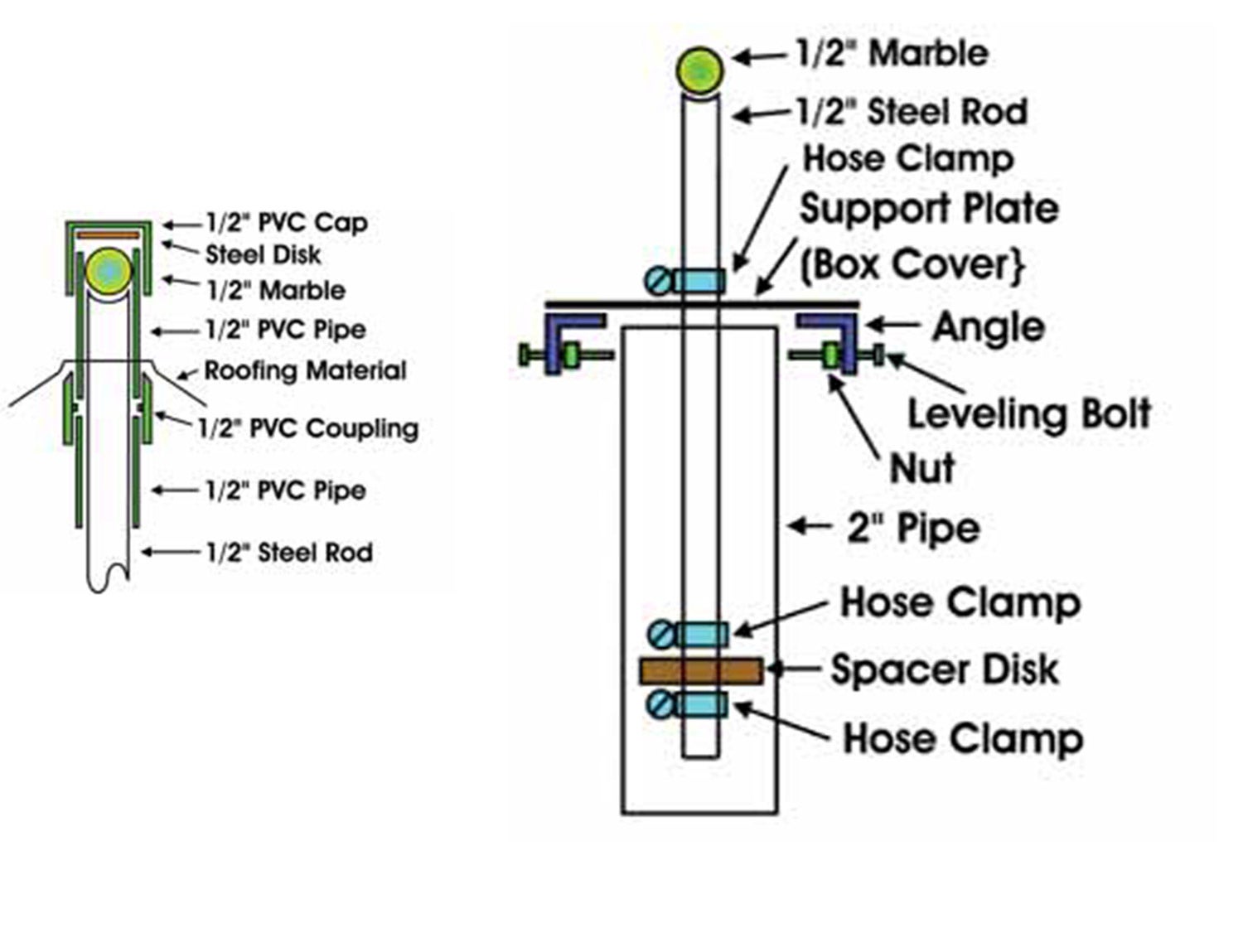
Drill a half-inch hole in the center of the 4-inch blank box cover, which will be the support and centering plate. Drill a quarter-inch hole in the center of one side of each of the three aluminum angles for the quarter-inch centering bolts. Space and mount the angles evenly (120) around the half-inch hole in the box cover, leaving enough room to fit over the steel pipe. Make the spacer disk (with half-inch hole) to just fit inside the pipe (Photos 2 and 3).
Grind an eighth-inch dimple in the top of the half-inch rod, using a hobby rotary tool, for the bottom-bearing surface. The radius of the dimple should allow the marble to rest at its bottom (Figure 3). File the half-inch knockout so that it will fit inside the PVC cap (it should almost fit already).
Place the knockout (steel disk) into the cap and glue the cap onto a 4-inch length of PVC pipe. Slightly bevel two sides of one end of the PVC coupling so that it will fit into the center ridge of the U-panel. Put the PVC pipe through the hole in the center ridge and glue the coupling to it. Cut another length of half-inch PVC pipe (about 7 inches) so it will extend from the coupling through the hole in the box cover mounted to the cross EMTs (Photo 1).
when it comes to sensitivity. Figure 4 (right). Mounting and leveling details.
Solidly mount and level the 2-inch pipe into the ground with about 4 feet remaining above the surface. Using the hose clamps, attach the spacer disk near the bottom end of the half-inch rod. Slide the support plate followed by a hose clamp down the rod about a foot and tighten the clamp (remember this clamp supports the weight of the tetrahedron). Put the rod into the steel pipe, and level and secure it with the leveling bolts (Figure 4, Photo 3).
operation.
Place the marble or ball bearing (with a bit of grease) in the dimple and slide the tetrahedron in place. The support plate clamp may be moved up or down to provide clearance for motion. Some weight will have to be added to the front to balance it. When the PVC pipe is not dragging on the sides of the steel rod, the balance is good. (See the black pipe used to balance the tetrahedron in Photo 1.)
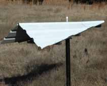
Photo 4 shows the tetrahedron in operation. Other materials such as plywood can be used, but keeping it light will enhance its sensitivity, and metal will last for years.
![[Credit: magniX]](https://www.kitplanes.com/wp-content/uploads/2026/04/Magnix.jpg?w=218&h=150&crop=1 "magniX Opens Pre-Orders for an Electric Engine Aimed at Homebuilders")


Sounds like a neat DIY project, but unfortunately all that remains is the text of the article, and no pics or drawings are included any longer.
The second “Figure 1” in the updated post is really “Photo 3. Support plate and leveling bolts.”
Thanks, Dustin. We’ve updated the post with images.
Guys, The second “Figure 1” in the updated post is really “Photo 3. Support plate and leveling bolts.”
Comments are closed.