Back in the September 2014 issue of KITPLANES, I wrote about holding odd-shaped parts on the lathe [“Home Shop Machinist—The Lathey Guy’s Guide to Work Holding“]. This month I’ll discuss the ins and outs of work-holding strategies for large diameter and long and slender parts on the lathe.
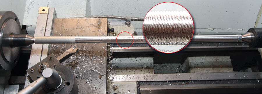
Chatter occurs when the workpiece flexes under the cutting force. The close-up inset shows what happened on this -inch bar between centers. The unsupported middle section is rough and pock-marked with wobbly lines.
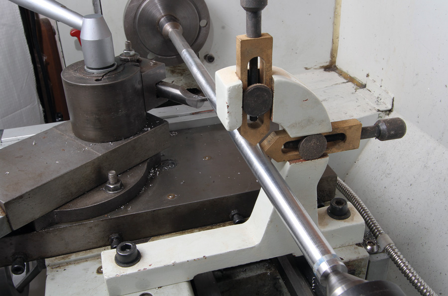
Every lathe comes with a steadyrest and a follow-rest. The steadyrest bolts directly to the bed of the lathe and provides three-points of contact (at 0, 120, and 240) to prevent deflection. You can use it to support the free end of a long or large-diameter part, or position it anywhere along a slender part to provide support from deflection and chatter. The follow-rest is typically used only for parts turned between centers. It’s called a follow-rest because it is bolted to, and moves with, the carriage. Two adjustable rub-blocks are at angles opposite the cutter to prevent the work from bowing or otherwise flexing, thereby eliminating chatter marks and dimensional defects that would otherwise occur.
What’s chatter? Chatter is caused by the pressure of the cutting tool pushing the workpiece off-axis. As the part deflects, the cutting pressure decreases to the point where the part will spring back, where upon it digs into the tool again. This deflection-and-spring-back cycle is characterized by a high frequency howl, vibration, and a nasty pattern on the part.
Because of the type of work I do, I rarely use the follow-rest. But there are certain jobs where the follow-rest would be a necessity: such as threading a long lead screw or making plane shafting. But if your bar has steps or a taper, or has other features, like a keyway or flat, the follow-rest is not going to work. That’s where the steadyrest comes in. Since the steadyrest doesn’t traverse with the carriage, you can fix it wherever you need support. It all depends on what you want to do.
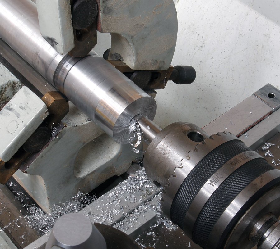
Say you want to face off the end of a large pipe or tube. It can be clamped in the reverse jaws no problem, but if it is a bit too long, the force of even the lightest cut can leverage it right out of the chuck.
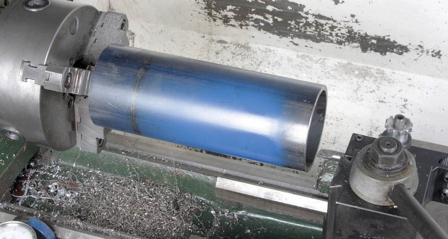
Don’t do this! This length of large-diameter pipe is gripped tight with the reverse jaws (the clamping jaws are on the inside pushing outward against the ID of the pipe), but it’s too long to safely face-turn the unsupported end. Even the lightest cutting forces against the end could send it flying.

Do this! The same pipe, this time supported at the free end by the steadyrest. With the rub-blocks adjusted to prevent any deflection, any type of cut (facing, boring or turning) can be made safely.
Long bars or tubes are sometimes less than perfectly straight. It’s possible to chuck a long bar in the lathe and set the steady at the distant end and have it off-axis. So it’s a good idea to reference the centerline of the spindle. You can do this with a dial- or test-indicator. Zero the indicator at the chuck, then traverse the length of the bar to see if it’s running true (this is done with the lathe off). A slight discrepancy can be corrected using the rub blocks on the steadyrest to coax it back in line. About 0.005 inch per foot is my personal limit, but it depends on the material. Extruded aluminum bars can be out of round by that much. If a ground or drawn 4130 bar is out that much, you should check to make sure it’s not warped or bent, or if it’s being compromised by some debris in one of the chuck jaws.
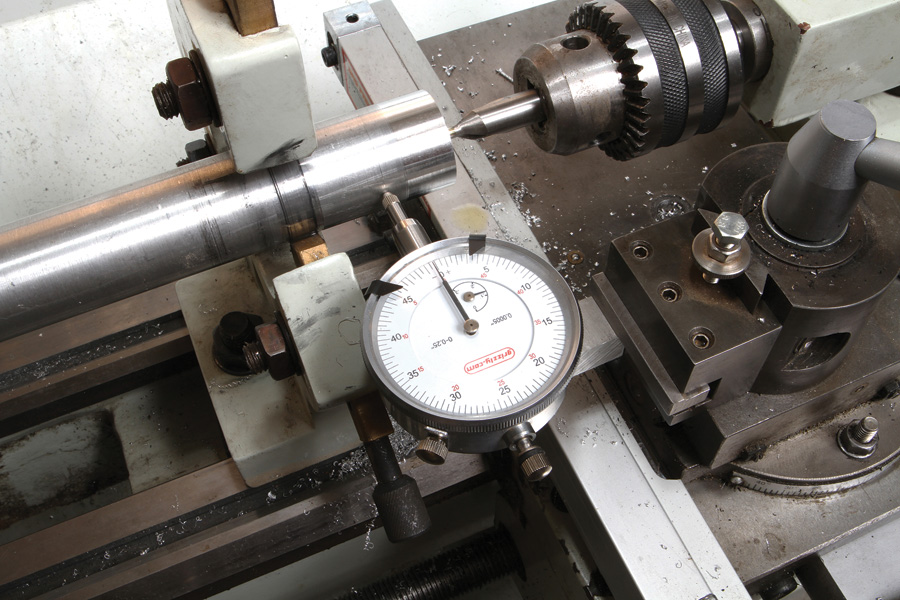
Mounted in tool-holder, this dial indicator is used to verify the centerline is on target for drilling.
If your workpiece is straight and on center, set the steadyrest into position and adjust each rub block until they’re almost touching. About 0.004 inch, which is the thickness of a piece of paper, is perfect. Then carefully adjust each rub block until it just touches the work, but with no pressure. Dab some heavy oil on the block, and you’re ready to turn. Ideally, the rub blocks should just barely touch the workpiece. Even then they will burnish the part where they’re rubbing. Keeping the blocks well-oiled with heavy oil (30W or higher, or way oil) will prevent them from heating up and binding.
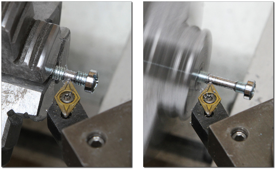
Turning this 8-32 screw into a 1-1/4-inch long crossbar required nibbling inch at a time and as close to the chuck as possible. Note the positioning of the diamond insert and use of the left-hand tool holder to reach the narrow gap between the screw head and chuck.
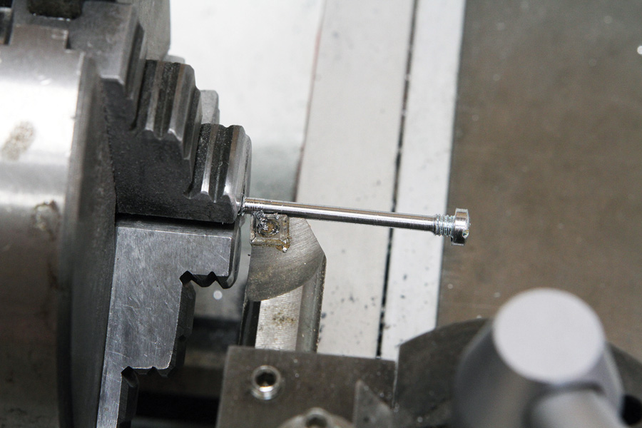
Once enough space allowed, I switched to the right-hand tool holder to continue to nibble the threads away until the bar was long enough to cut to length. Prior to cutting off, I polished the tool marks away with 320- and 400-grit sandpaper.
Steadyless Turning
Often long parts can be satisfactorily turned without using a steady. As long as they fit through the spindle, you can turn a segment, reposition the part in the chuck, turn the next segment, and so on. The drawback is there will be tell-tale signs you used this procedure. If dimensional accuracy is not that important, the evidence can be eliminated by polishing it on the lathe with 180- then 220-grit sandpaper.
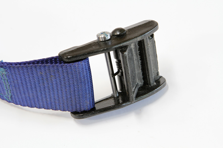
I recently had an occasion to employ a version of the turn-reposition-turn method to repair a broken cam buckle for the battery hold-down strap on my Jabiru. The buckle went limp when the crossbar—the part that keeps spring tension on the clasp—snapped off. Since a new strap would likely have the same weak point, I repaired it with a 0.100-inch diameter stainless-steel crossbar turned from a two-inch long 8-32 fillister head screw. I left about 3/16-inch worth of threads near the head. This design allows the screw to be tightened securely, but without tensioning the frame (see photos). I considered using a spring pin, but decided the die-cast frame might be too fragile.

![]()
Bob Hadley is the R&D manager for a California-based consumer products company. He holds a Sport Pilot certificate and a Light-Sport Repairman certificate with inspection authorization for his Jabiru J250-SP.
Got a question for or job that needs assistance from the Home Shop Machinist? Send us a description of the part and where it’s used. We’ll consider it for a potential topic for a future HSM column. If we pick your request, be prepared to supply the raw material and, if it’s part of a published plan, access to the original design drawings. Send inquiries via e-mail to: [email protected] and put HMS in the subject line. Due to liability, certain items may be limited to the construction of a demonstration part for instructional use and display only.

