As homebuilders, we are accustomed to doing a lot of preliminary and/or tooling work to build one or two pieces for our aircraft. The work may be as simple as a wood block used to form a piece of metal or as complicated as a full airframe jig. Either way, the effort usually is rewarded in a better part.

Electronic pieces are no different. But the effort to design, lay out, print (and expose and develop) the resist pattern, etch, clean, drill, stuff and solder a printed circuit board (PCB) for only one example just isn’t worth the effort. Still, the performance and ruggedness of PCBs are desirable in our creations.
My Example
The need for an auxiliary fuel transfer pump controller in my GlaStar Sportsman serves as an example of a construction method that achieves this goal without nearly as much effort. A commercial controller, which does nothing but warn you when the source tank is dry, costs $300 and must be installed at the tank. This one, which I think is more capable, costs less than $25 in parts and mounts behind the panel, saving precious panel real estate.
Let me back up and explain the impetus for this project. The Sportsman has 15-gallon mains and 10-gallon auxiliaries in the wings, and they are too far apart to be interconnected to act as one tank. For operation on long cross-country flights, the procedure is to draw down the main tanks and then pump the fuel from the auxiliary tanks inboard. Some pilots do this manually a little bit at a time, and some choose to draw down the mains by just more than the capacity of the auxiliaries and transfer all at once.
With my system, both transfer buttons are pushed an hour into the flight and forgotten. Every half hour later they are pushed again. The controller circuit, nothing more than a simple timer, runs the pumps and turns them off automatically. This routine has several advantages. There is no worry about over filling the mains and pumping fuel overboard. The pumps turn off automatically, so I can’t leave them on with dry tanks, warning or no warning. And I have at least ⅔-full main tanks until all fuel is transferred. This not only gives me a 2-hour window to remember to transfer more fuel, it also provides the maximum range flexibility if the transfer system fails.
The Nuts and Bolts
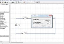
Figure 1 shows the final schematic for the controller; one is needed for each tank. It is a programmable timer that is adjusted to turn on and transfer exactly 2 gallons each time the transfer button is pushed, which takes about 4 minutes. The button includes an LED that shows the pump is on.
The final schematic is developed using a “breadboard.” Photo 1 shows a commercial solderless breadboard but the special plug-in sockets are available for less than $11 (Mouser 383-X1000). In actual development it didn’t look nearly this clean. There is much replacement, adding and removing of components. Use #22 solid wire to make the jumpers. Once the circuit is working as desired, we diverge from the PCB method.
The one-off example is built on a fiberglass sheet pre-punched with 0.042 holes on a 0.1-inch grid pattern and coated with copper on one side (Mouser 574-169P44WEC1). Twenty-one dollars get you a 4.5×17-inch piece, enough for several projects. Where the leads stick through, the copper is first countersunk routed away from the edge with a Dremel 117 cutter. The exception is any lead going to ground. Here the copper is unaltered, and the lead is soldered directly to it. So the copper side forms a broad ground plane that helps tame electronic noise and gremlins.
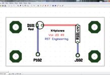
Determine component placement and connection-wire routing on grid paper with colored pencils (you will do a lot of revising). Quarter-inch-grid paper representing each 0.1 inch works well. This is easier than PCB layout because there is no restriction on crossing wires and no need to route ground connections. But it is worth the effort to place components so as to minimize crossings. Connect the signal lines first, and finish by wiring all the power lines in red. Photo 2 shows the actual work on grid paper. It is about the seventh full iteration with many small region retries in between. Figure 2 shows the final routing for documentation purposes of both left and right controllers on a 2×3.8-inch board. The insulated leads are shown with dots; the grounded leads have the rectangle.
Photo 3 is the board partway through routing out the insulated lead holes. Each hole to be cut back was marked with a thick point felt pen. The cutting can be done by hand as shown, but more consistent results are obtained using the Dremel drill press accessory.
The components are mounted on the insulated side and tack stabilized with hot-melt glue. Wire-wrap sockets are used for the integrated circuits. Their long posts make it easy to connect wires slightly above the copper surface. The excess post is then clipped off when you’re done. Wire wrap trifurcated terminals (Mouser 574-T49/C) are used for off-board wire connections and the jumper array.
Shorts, Not Bermuda
Two issues relating to short leads are illustrated by the relays. Drill out any short lead hole to 3⁄32 inch. Before inserting the component, tin each lead and also some #22 solid wire. Solder the two together and cover with heat-shrink tubing to serve as a through hole insulator. The heat-shrink holds the joint together if the solder melts while connecting another wire. Not all leads are on 0.1-inch centers. For long leads, just bend them to meet the grid. This was done with the 2N4401 transistors. But with the short leads on the relay this is not possible. Just drill out two or more adjacent holes as needed.
The leads themselves can be used to connect to other components. Use small needle-nose pliers to bend the lead above the copper surface. Cover each connection with insulation or heat-shrink tubing. Use bare solid wire for daisy-chain connections. Solder and insulate one connection at a time, wrapping the wire once around each lead to be connected. For power leads to the relay contacts use #22. All other lines use the smaller #24 solid wire for clearance. Work from one side to another, clipping excess leads/wires as a connection is finished. When completed, briefly apply a heat gun to the component side to smooth and flow the hot glue.
After final testing, apply several coats of Performix liquid electrical tape, available at Wal-Mart, to the copper/lead side of the board. This synthetic rubber product is longer lasting than the vinyl product sold elsewhere. The spray-can version produces smooth coatings, but the less expensive brush applicator works just fine. When coating, mask off the corners where the mounting hardware is located to be able to ground the board to the case.
Photo 4 shows the completed lead side of the controller halfway through the coating process. The upper half of the board looked like a rat’s nest with wire leads using random insulation; the lower was done with heat-shrink tubing. Although the heat-shrink part looked better, either method works fine and both look the same when done. Add Liquid Tape until all wires are encapsulated. When the coatings are dry you have a vibration- and weather-resistant circuit ready for mounting and cabling as shown in Photo 5. The circuit breaker/switch is used to turn off the controller early if needed.
Projects like this can be a lot of fun, solving problems inexpensively while you learn a new skill. What’s not to like?


