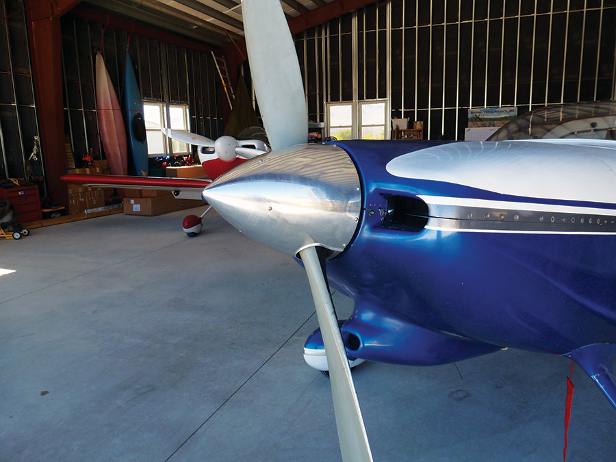
I have been in love with the look of aluminum spinners on aircraft for as long as I can remember. To me it just looks right-plus there are other advantages. Here are the pros:
Consistent weight distribution, thus is less likely to cause balance issues.
- No issues with hole elongation during annual removal and inspection cycles.
- Can be polished to achieve that shiny finish.
- Accurate prop flange cut-outs.
- Flanges are flared to increase strength.
- No pinholes.
- Looks great!
- Can also be painted if desired. (But why would you want to?)
And here are the cons:
- Slightly heavier than a fiberglass spinner.
- Requires more care when installing as mistakes cannot be repaired like they can with fiberglass.
In 2005 while I was still flying a Zenith 601XL(B) with a Jabiru 6 cylinder engine, I purchased my first spinner for my two-blade Jabiru wooden prop from Allan Barton at Cummins Spinners. A few years later, when I upgraded to a three-blade carbon-fiber Petroni prop for the Zenith, I immediately contacted Allan and asked him to supply me with a new spinner to suit. He even offered to sell the old spinner for me.
When I started building my RV-7, there was never any question in my mind about what was going to be on its nose-it had to be a polished aluminum spinner. The only thing stopping me was, at the time, Cummins did not have a spinner for a fixed-pitch Sensenich prop. So each year while I was building the RV and still flying my Zenith to airshows, I would drop by and visit Allan at his stand and ask him how he was progressing with the development of my spinner. Year after year, he gave me the same answer: “No, not yet.” And so we continued to play our little game.
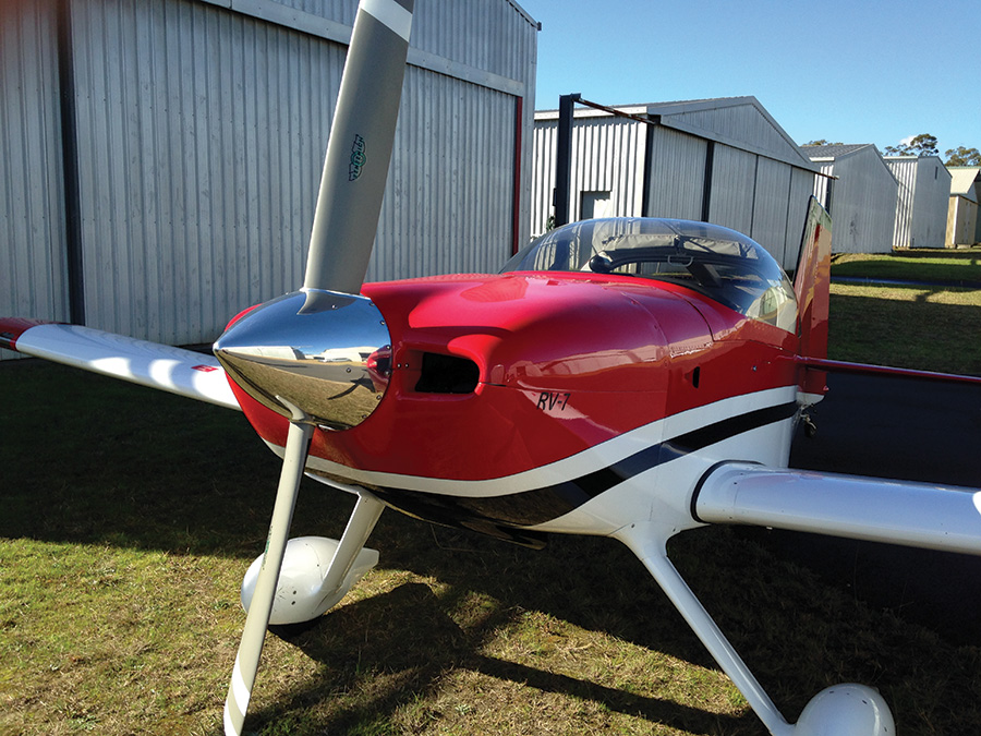
Eventually in 2012, after four years and two months of building, my RV-7 was up and flying. It sported Van’s standard fiberglass spinner, which looked good, but to me, not anywhere near as good as a polished aluminum spinner.
However, Easter of 2013 would be my turning point. This time Allan surprised me by asking if I would like to volunteer to test a new Sensenich spinner for them. My response was, “When do you want me in Bendigo?”
“Monday would be fine,” said Allan. And that’s how it played out. It was Good Friday when my bluff was called, so all I had to do was convince my wife Anne-Marie to let me go out again to play.
Cummins Spinners is located right at the airport making it very convenient for us pesky customers to drop by. To cut a long story short I flew into Bendigo Airport Monday afternoon, parked the RV in Allan’s hangar, and we began the process of fitting a new spinner.
1. Remove the old spinner, front plate, prop, back plate, and spacer, remembering to mark everything for orientation. The old spinner and its front and back plates can be set aside; these parts can’t be reused because it is too difficult to measure and mark the locations of the holes that have been previously drilled.
Place the entire assembly on a bench in preparation for marking and drilling the new spinner and back plates. Use tape to mark the orientation of the prop, spacer, front and back plates.
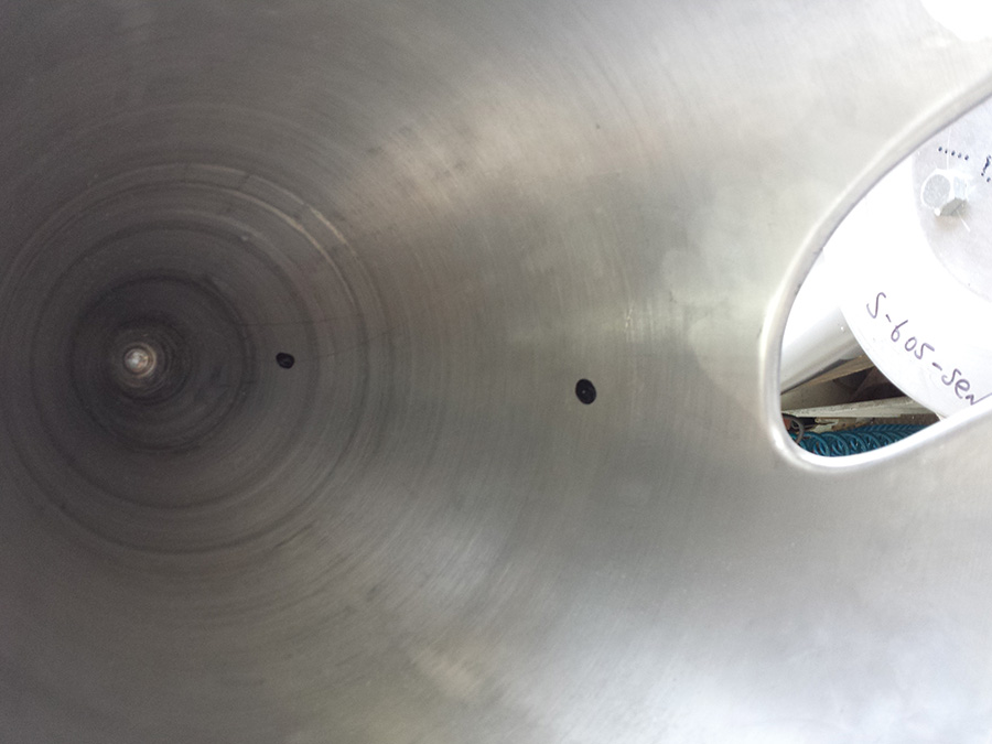
2. Mark the inside of the aluminum spinner with a Sharpie to indicate its orientation relative to the prop.
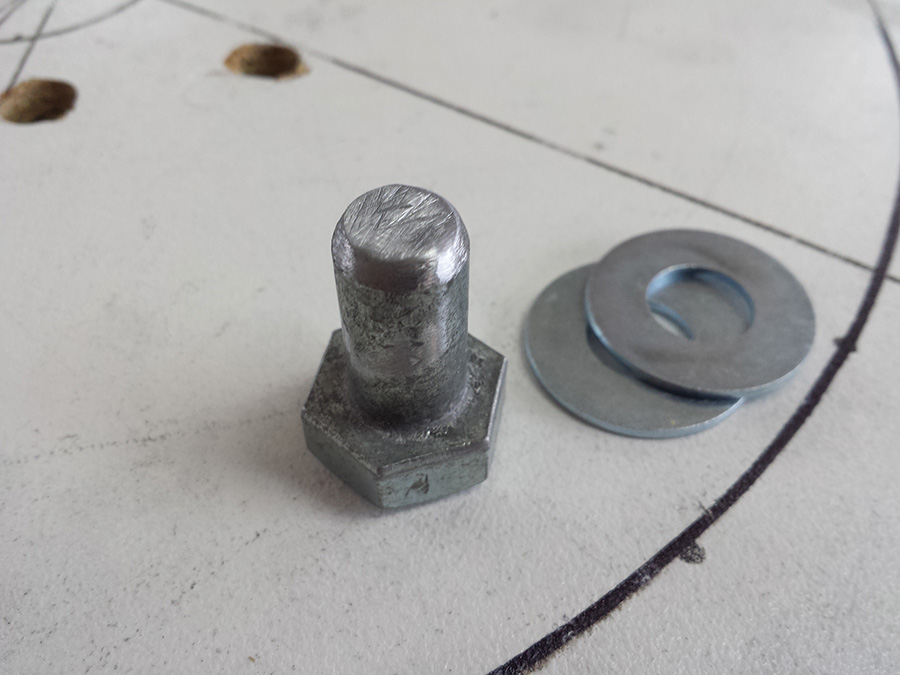
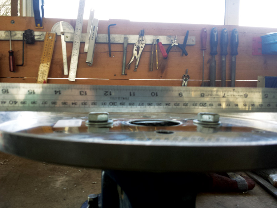
3. Cut the ends off some hardware-store bolts to use as locating pins in place of the prop spacer. Use enough washers to ensure that the back plate is not compressed when the prop is placed on the back plate. You can also use wooden spacers to properly support the back plate. This step is extremely important! The back plate must be fully supported and sitting flat to stop the back plate edges from spreading and causing an issue with the position of the mounting holes in the back plate.
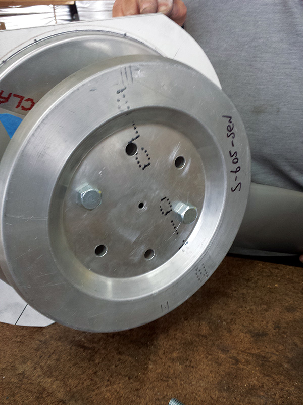
4. Position the prop face down and locate the back plate using the tape that was previously applied to ensure correct orientation. Next, insert the locating bolts.
5. Use enough washers to raise the bolt heads, making them level with the flange of the rear back plate.
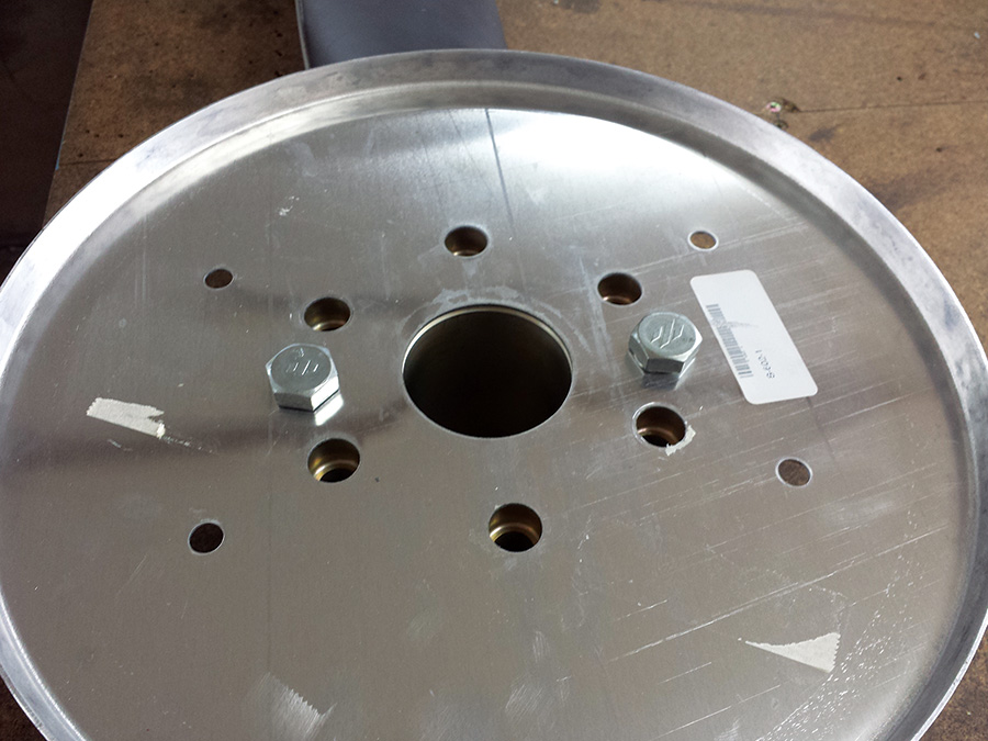
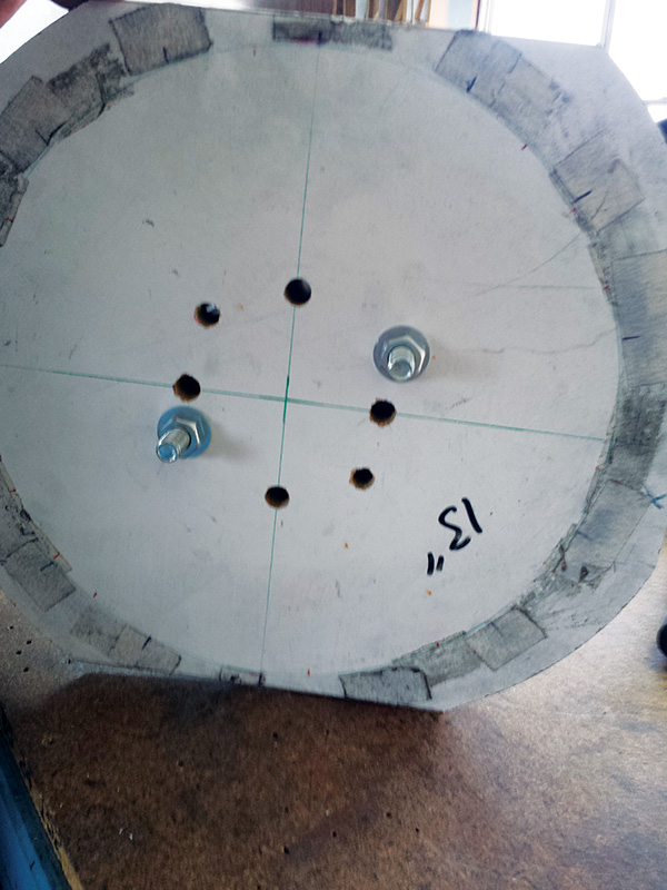
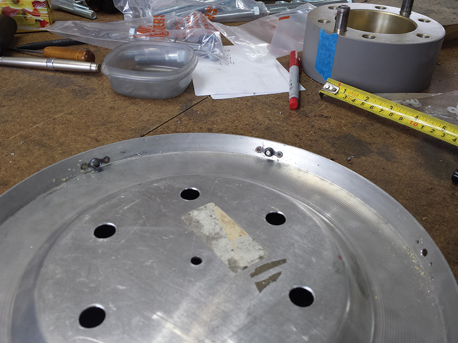
6. Use tape on the backside of the back plate to hold the bolts in position. The second photo shows the front side of the back plate with the locating bolts inserted.
7. Flip the entire assembly right side up.
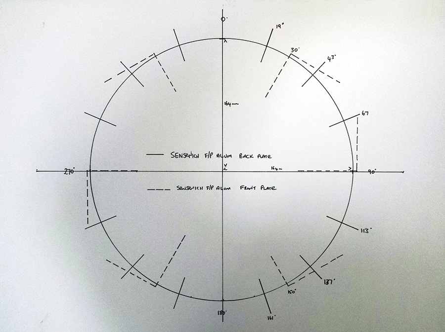
8. Fasten the appropriate template to a piece of plywood or particle board that you have drilled to suit your propeller bolt pattern. The template will be used to mark the position of the holes that will be drilled to install nutplates on the front and back plates of the spinner.
9. Install the spinner front plate using two hardware-store bolts that are long enough to bolt the entire assembly together (propeller, front plate, back plate and plywood template).
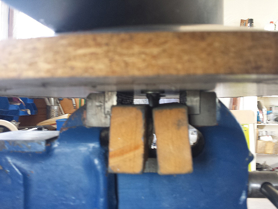
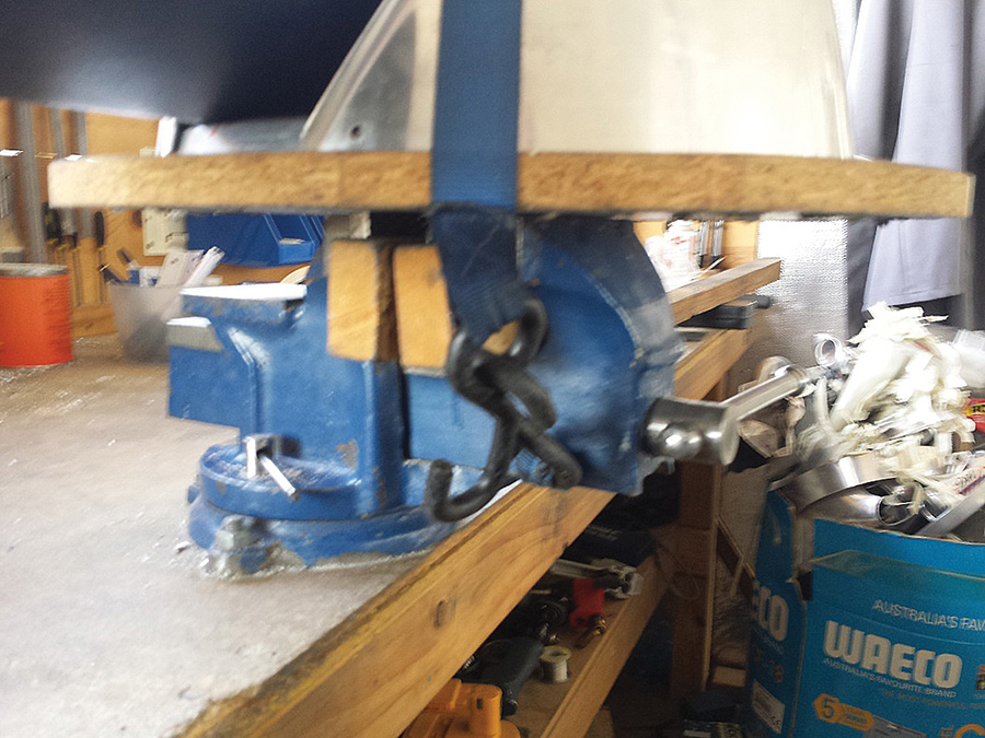
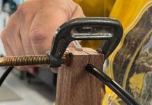
10. Clamp the through bolts holding the prop and spinner front and back plates into a vise using wooden blocks.
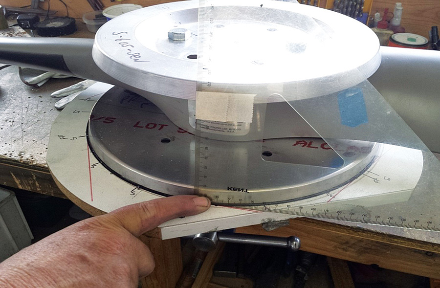
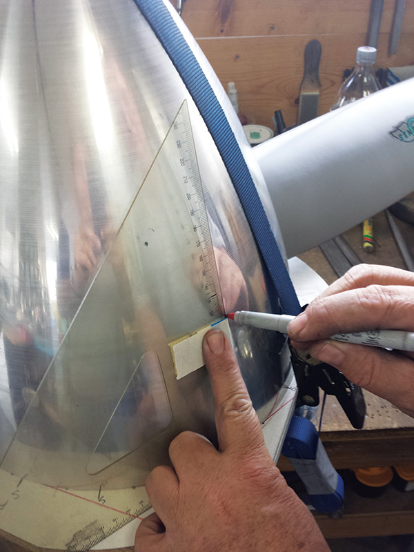
11. Determine the center of the front- plate flange using a triangle. Use masking tape to mark the center point on the triangle as shown-this will be used later. To ensure your measurements are square to the spinner cone, the bottom of the triangle needs to line up on one of the perpendicular lines drawn on the supplied template (red lines in the picture).
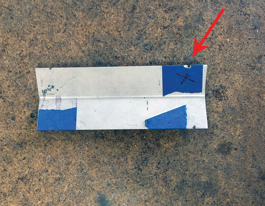
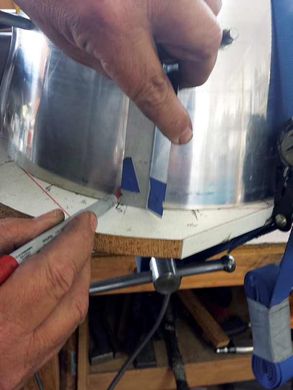
12. Measure the center point of the back plate face and make a marking tool with a slot filed at the height of the center point. This tool will allow accurate marking of the drilling points for the back plate.
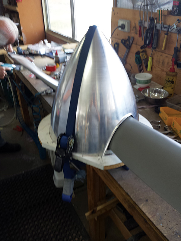
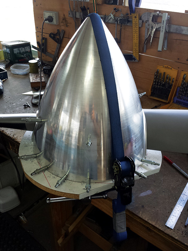
13. Place the spinner over the assembly that you have clamped into the vise, and align the spinner cutouts to ensure equal spacing around the propeller. Use a ratchet strap placed around the spinner and vise to firmly clamp the spinner into position so that it does not move when drilling.
14. Mark the top and bottom of the spinner with the center point measurements of the front and back plates taken earlier. If the ratchet strap stops you from marking any of the holes, drill and Cleco the holes that are accessible before moving the ratchet strap to mark and drill the remaining holes.
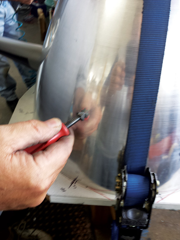
15. Use a suitable tool to make an indent for each hole; this ensures that your drill bit does not wander. Important! Do not use an automatic center punch as this could damage the cone.
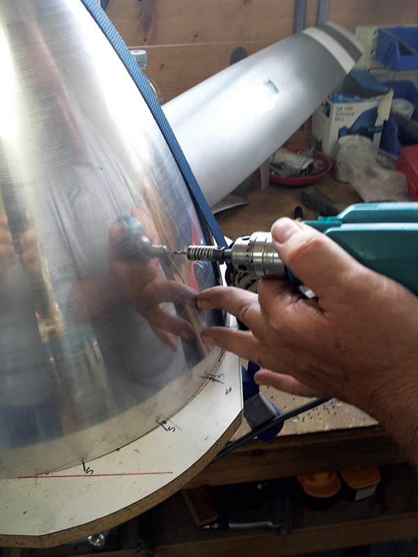
16. Drill only the front plate at this stage, adding Clecoes as you go to ensure no movement. Once the front plate has been drilled and Clecoed, move onto drilling the back plate. All holes should be drilled to 3/32 inch (#40 pilot holes) at this stage.
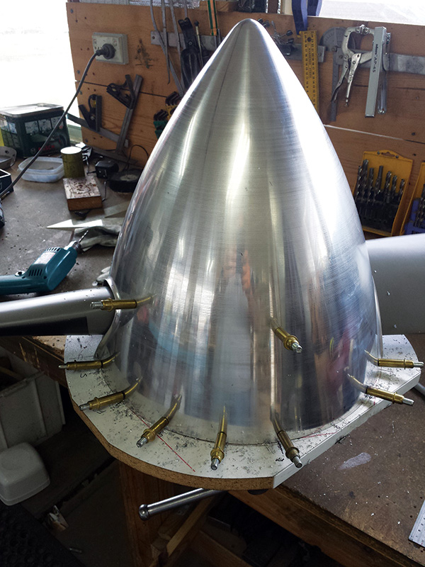
17. Once the spinner has been drilled to #40 and each hole secured with a Cleco, enlarge each hole one at a time for #8 screws using an appropriately sized drill bit. Use Clecoes to maintain proper alignment.
18. Before disassembling the spinner, check once again that you have marked the spinner, prop, front plate, and back plate to ensure correct orientation for reassembly. Replace any masking tape used earlier with a black Sharpie mark.
19. Follow standard aircraft construction techniques and ensure that all holes are properly deburred before installing nutplates. Install nutplates at each hole location using the countersunk rivets provided.
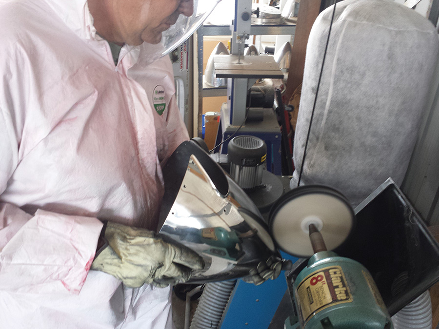
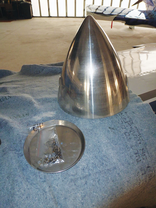
20. Once you have installed the nutplates, it’s time to think about polishing. The polishing machine that Cummins Spinners uses is an 8-inch bench grinder. The first polishing wheel is stitched cotton, 8×1 inch. Use brown/tripoli bar polishing compound. The second wheel is loose calico, 8×1 inch. Use green/stainless steel buffing compound. The final clean is done by hand with Silvo silver polish.
The photo shows the author learning to polish, being very careful not to let the wheel catch the edge of the spinner and throw it across the room.
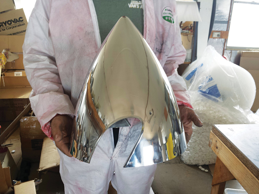
21. After two hours of polishing, here is the finished product, ready for installation on the author’s RV-7.
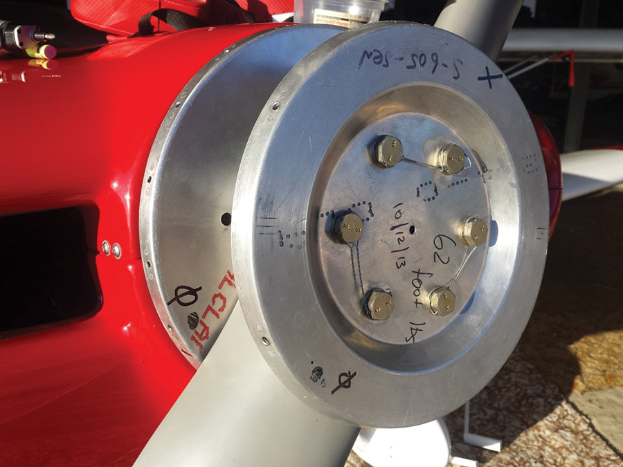
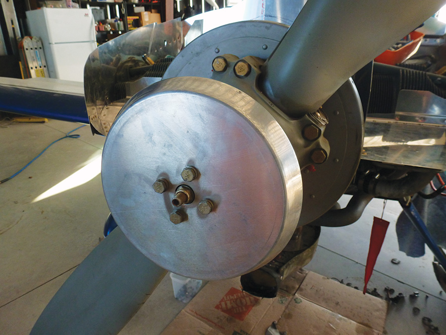
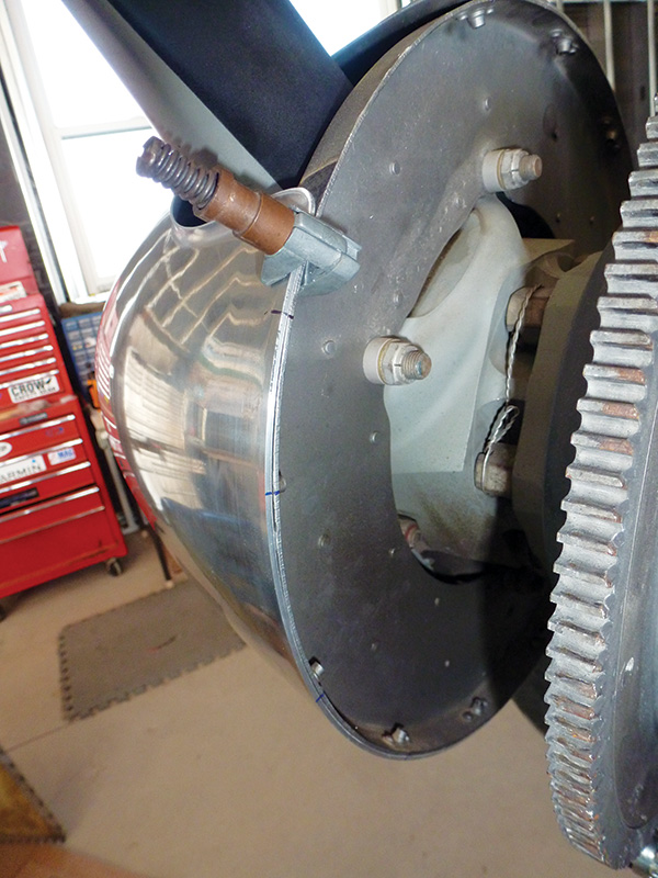
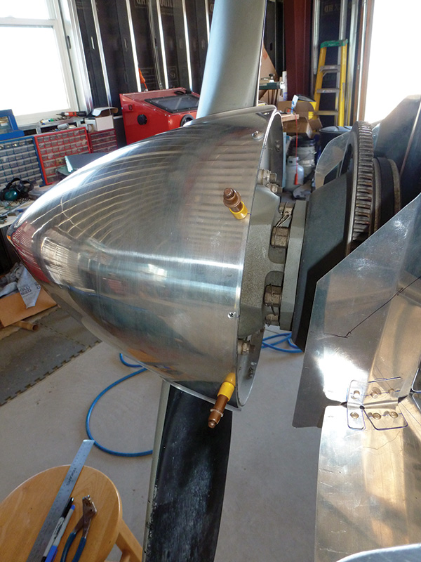
22. Reassemble the prop spacer, back plate, prop, and front plate. Remember to torque the bolts to the correct setting and apply safety wire.
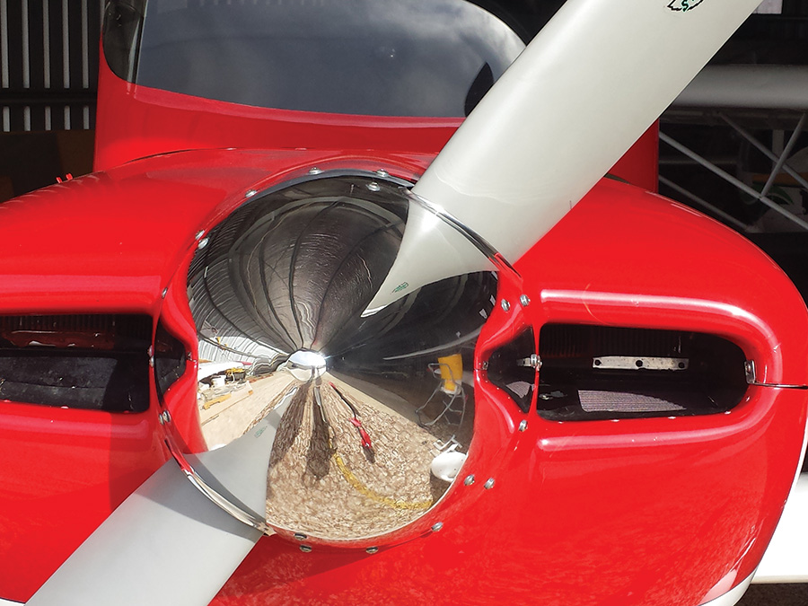
23. Attach the spinner and you’re ready to fly!

