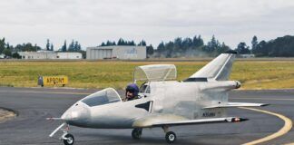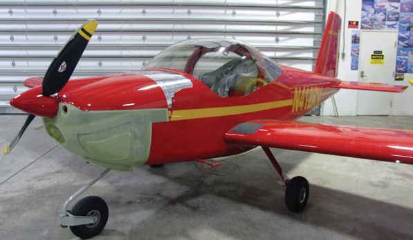
The Van’s Aircraft RV-12 kit prototype gets some factory tweaking.
In the first installment of this series, we described wing and flaperon construction and noted that the second kit segment available was the forward fuselage. Shortly after we got the forward fuselage segment, the empennage/tail cone subkit became available. Because new RV-12 builders will receive the tail cone and empennage subkits first, followed by the forward fuselage and then the wings, we’ll discuss the tail kit in this episode. This is out of chronological order for our project, but in the right order and probably more useful for newer builders.
Getting Started
The Van’s Aircraft factory is less than an hour’s drive from our home in Oregon’s Willamette Valley, and a longbed pickup truck served to take delivery of the tail cone and empennage kit. The longest pieces are the tail cone skins—just shy of 9 feet long. The next-largest part is the stabilator skin, which is about 8 feet long and comes from the factory with the leading edge pre-bent. Benefiting from being able to take delivery at Van’s and needing no crating, we loaded our kit parts in less than 5 minutes from a cart at the back of the factory. A large envelope contained the 11×17 building manual plus inventory sheets for the tail cone/empennage segment.
Back home, my wife, Lois, completed the inventory in less than an hour. The list of parts is considerably shorter than either the wing/flaperon or forward fuselage kit. All components were present and counted—except for two leading-edge stabilator ribs numbered HS1206. And an error had supplied three VS1206 ribs for the vertical stabilizer when only one is necessary. The factory quickly supplied the missing HS1206 ribs, and I returned the unneeded vertical stab ribs.
An Easy Sequence
It’s easy to see why Van’s Aircraft and many other kit airplane projects begin with the tail. Construction here is relatively simple and less expensive than wing or fuselage sections. If a learning-curve mistake here wastes a part, replacement is likely to be less than devastating. Sixteen pages of general guidance including planset conventions, construction tips, design philosophy and parts recognition precede construction details. (The same boilerplate set came with our wing kit because we received it first.)
As noted in the first article of this series, building amounts to following specific numbered instructions that are accompanied by detailed perspective and exploded-view drawings. Empennage building begins with preparation of the four formed, bent, drilled and slightly machined aluminum brackets that capture the rudder hinges. As always, factory parts require removing a protective blue vinyl film, smoothing edges with a file, and deburring rivet and other holes if their edges are sharp. After placing a bearing assembly between two bracket halves and using Clecoes to hold the pieces together temporarily, solid rivets are squeezed to turn each three-piece unit into a flight-worthy rudder bracket/bearing assembly.
Vertical Fin and Rudder
A factory-bent and -drilled U-channel plus left and right sparcap stiffeners make up the vertical fin trailing-edge spar. Match-drilling through factory-punched holes is required, unlike most rivet operations where all holes are punched to rivet size. The first of many nutplates is squeeze-riveted in place. In many cases, skins need to be dimpled and nutplate legs need to be countersunk to accommodate flush rivets. Engineers at Van’s have designed the solid-riveting operations so that you can get at them with a rivet squeezer. But in some cases, we found it advantageous to use a rivet gun and bucking bar.
Five ribs—four horizontal and one vertical—make up the vertical fin skeleton as they are Clecoed and then riveted to the spar. Except for the bottom leading edge of the fin, the entire skin is in one pre-bent Alclad aluminum piece. Eighteen #8 flush nutplates are attached to the bottom forward part of the skin before it is pull-riveted to the fin skeleton. Flushhead 8-32 screws eventually fasten the lower forward skin to the 18 nutplates in the main fin skin and to a rib riveted to the top fuselage skin. Upper and lower rudder-hinge assemblies are bolted to nutplates installed previously in the fin spar.
The constant-chord rudder consists of a spar, five ribs, bent skin and hinge brackets. A painted factory-made double control horn completes the rudder except for the fiberglass rudder tip. A pair of stabilator anti-servo tabs is built next and set aside to await completion of the stabilator itself.
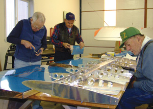
Jim Ashford (left), Doug Davis and Bob Schwarzler prepare the stabilator skeleton and skin for getting them together.
The Stabilator
The all-moving pitch-control surface is a first for a Van’s design. The reason is that a stabilator can be smaller than an elevator/horizontal stab configuration, and keeping the horizontal tail short enough for highway width limits was a primary goal.
Stabilator construction begins with a beefy and complex box spar with its inboard forward, aft, top and bottom webs, square ribs and nutplate attachment for hinge brackets, upper and lower control horns and counterweight attachment devices. Steel parts come welded and painted. Nutplates of several sizes are required, and some attach points require flush rivets.
Once the spar is built, eight sets of nose and main stabilator ribs are riveted in place. There is a full-span main trailing-edge spar to which long piano-hinge halves for the anti-servo tab halves are installed in the center of the stabilator, along with a pair of rear ribs at each stabilator tip.
Deburring and then fastening the entire single-piece stabilator skin to the skeleton was a confidence-building joy. Using an awl to shift ribs slightly left or right caused the rivet holes to line up, permitting quick work pull-riveting the entire stabilator. Following the instructions, we installed the steel counterweight with its 5.5 pounds of lead castings and then removed this assembly after assuring that the bolt holes to fasten it permanently were correct.
The Really Big Piece
The entire tail cone comes with the RV-12 empennage kit, and building it comes next. The first steps involved making three fuselage bulkhead rings (the manual calls them frames) from six stampings that are riveted together top and bottom. The rear frame halves are joined at the top with a plate that becomes the forward vertical fin attachment. Eighteen rivets combine the mounting plate, the frame halves and a stiffening bracket.
Four of the 9-foot tail cone metal sheets required breaking their riveted edges, which means bending the metal down a few degrees about a quarter inch from the edge so that riveting leaves no gap between the two metal sheets. Sometimes we used a special roller meant for this, but it can also be done carefully using a straight piece of wood about a foot long.
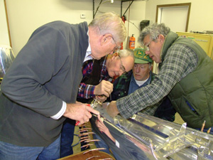
“Shall we vote on how this goes?”
I also prepared the complex rear fuselage bulkhead. It consists of a main piece and a stiffener, eight nutplates (for the vertical fin spar), four brackets for the stabilator hinge and 89 rivets of various types, shapes and sizes. There is also a tail-tiedown fitting to make from an extrusion. It requires using a drill template and a 3⁄8 x 16 tap to run threads an inch deep. The tail tiedown extrusion, which includes a factory-machined slot for part of the pitch trim system, is then riveted to the bulkhead. I found it much easier to “buck and bash” the heavier eighth-inch rivets with my rivet gun and bucking bar than to hand-squeeze them. The bulkhead is small enough that I could hold it in a wood vise, then sight and hold the bucking bar with one hand while positioning the gun for a straight shot with the other hand.
A few rivets went askew and had to be drilled and redone, but aviation rivets have a dimple in the factory head for easy centering, and drilled rivets usually come out without enlarging the hole substantially. Although pulled rivets are easy, really fast, and permit riveting where a bucking bar can’t go, I’ve done enough solid riveting just on the RV-12 kit to enjoy the process.
After all this work including some preparation of the two side skins, we began the tail cone by placing the two bottom skins upside down on two sawhorses. The outboard edges of the bottom skins contain J-shape, factory-bent stiffeners, and there is a corresponding cutout in the left and right bottom of the three frames that allows hooking them to the bottom skin stiffeners. Assembly starts by hooking the frames to the right bottom skin (which is on the left because it is upside down). The three frames are Clecoed to the right bottom skin.
The left bottom skin is then swung into position to hook into the corresponding cutouts in the other side of each frame bottom. A few Clecoes hold the left skin to the frames, and now the inboard (centerline) rivet holes on left and right bottom skins begin to line up and are Clecoed. Next the left and right 9-foot bottom corner skins (with J-shape stiffeners built into their top edges) can be swung into position and Clecoed. We now have four tail-cone-length skins attached with Clecoes to the three frames. This is beginning to look like the bottom of an airplane! Masking tape is placed on all rivet holes within 7 inches of the forward end of the tail cone to prevent premature riveting in this area, which will attach to the forward fuselage.
Now the riveting fun begins. Each of the three rows of rivet holes (centerline and at the bottom corners) gets more than 100 rivets. I frantically alternated between poking rivets and removing Clecoes, while Bob Schwarzler and Lois, both armed with pneumatic rivet pullers, secured sheet metal permanently. We turned the riveted tail cone right side up, swung the side skin stiffeners into their cutouts and Clecoed the two sides in place. At this point we also Clecoed the rear bulkhead to the bottom and side skins.
Before the upper corners and top skins are attached, the double-sided static port system is installed while it’s easy to get at it. Strings for the stabilator control cables are run, and the five-conductor pitch trim wire is tie-wrapped inside the tail cone. Eighth-inch holes are in the side skins for left and right static ports (which are special pulled rivets that require removing the mandrils to let the air in). Plastic tubing and a T fitting complete the static system. The two pre-bent top corner skins are hooked, Clecoed and installed like the other pieces, followed by the single top skin.
Empennage Attachment
With the really big piece done, the entire empennage (fin, rudder and stabilator) is bolted to the tail for the first time. The objective is to check stabilator and rudder clearances. The process revealed that one of the four nutplates in the forward vertical fin was the wrong size. Fortunately, it is accessible from the bottom and was soon replaced. Stabilator installation includes poking the counterweight through the rear bulkhead, and that requires unbolting the counterweight tube so the assembly can be rotated 90° to fit the weights through the horizontal rectangular hole in the bulkhead as the stabilator is eased into position.
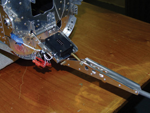
The electric pitch-trim system positions the stabilator’s anti-servo tab control tube.
Attaching the stabilator with its AN4-12 bolts at first required awkward handling in the center of the stabilator. Then I remembered my four-leg grabber tool, which made it easy to get the loose bolts in and out. After the clearance check, we removed the stabilator, and I worked on the upper and lower fiberglass tail fairing. It comes as two high-quality fiberglass pieces with accurate scribe lines for cutting away excess material. (Ours is an early kit. The tail fairing now comes with a later kit segment.) The process included rough cutting with hand saws, trimming exactly to the scribe lines (I used Perma-Grit bars and files), wet-sanding the parts, mounting eight nutplates in the lower segment, and priming and painting using rattle cans. Priming always reveals pinholes even in the best fiberglass parts. Some builders mix microballoons into epoxy resin to fill pinholes, but a neighbor suggested something much easier: lightweight spackling compound over the pinholes followed by fine sanding and another coat of primer. This worked well. The manual provides a detailed and accurate way to place holes in the two tail fairing parts and the rear fuselage where they attach. Nutplates are riveted into the fuselage.
Pitch Trim
Many parts make up the electric trim system, which changes the length of the tube that drives the anti-servo tab. The electric servo with its five wires (two for the motor and three that sense trim position) is mounted on a platform that changes angle as the stabilator is moved. The process includes checking the servo in its extreme positions and corresponding anti-servo tab clearances. After checking mechanical and electric operation of the trim system, we installed it permanently but removed the stabilator to avoid hangar rash.
Looking Ahead
Next in the planned sequence is the forward fuselage. Then comes the finish kit, which includes the landing gear and brakes, canopy, engine cowl, fuel tank and some other systems. The avionics package and the firewall-forward kit including the Rotax 912ULS engine should complete the kit, but a documentation package with placards and required ground and flight tests will follow. There’s lots left to do, but progress is quick, especially when working with a group of happy volunteers like ours.
For more information, call 503/678-6545 or visit www.vansaircraft.com.

