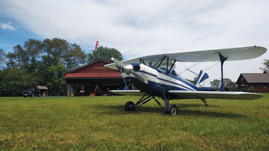
When I purchased my Starduster One (SA-100) earlier this year, the seller described it as “a handful” on the ground. During the thousand-mile cross-country trip home [“Biplane Cross-Country,” May 2018], I came to agree with him. I was no stranger to taildraggers (admittedly slower and tamer ones for the most part), but except for a few landings on a grass strip along the way, I never managed a landing I was happy with.
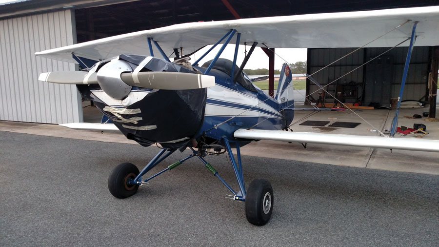
Part of the problem turned out to be a malfunctioning airspeed indicator, which made it difficult to get a handle on the proper speed during final approach and flare, but that didn’t explain the difficulty with directional control during takeoff and after touching down. Then, after I got the plane home, a head on-photo of the plane made it obvious that it was sitting one wing low, and a friend suggested that weak bungees on one side could account for the poor ground handling.
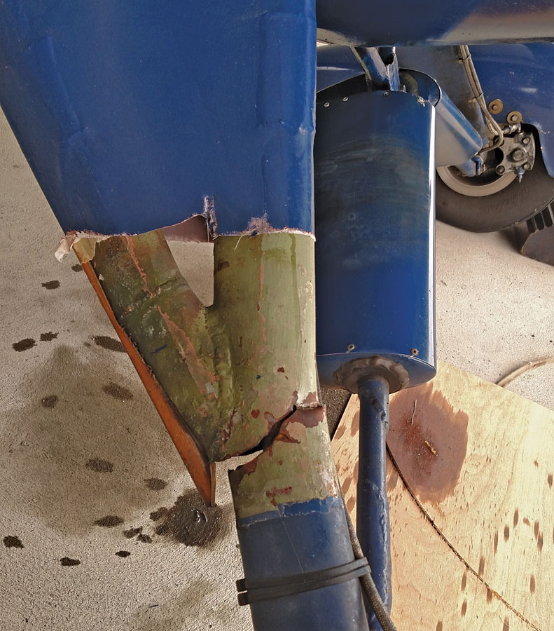
Removing the fabric revealed the extent of the damage. I was lucky to make it home!
I never even looked at the bungees. When I returned to the airport for the first time after getting the plane home, I could see that something was wrong under the fabric covering the right landing gear leg. Cutting the fabric away revealed a crack in the leg, which was visibly bent. Judging from corrosion on the cracked edges, it was clear that the crack had been present to some extent for quite some time, hidden by the glued-on fabric. With time (and no doubt some of my less-than-elegant landings during the trip home), it progressed to the point that the streamlined tube leg was completely severed, and only an inner round tube (not on the original plans) was holding it together. I was extremely lucky to make it home! I should point out that I do not blame the seller of the plane or the A&P who did the condition inspection, as until it actually bent, there was no way the crack could have been seen without peeling off the fabric.
A repair of the existing gear was an option, but it was obvious that it had already been repaired more than once. The logbook has an entry describing how the gear was cut and rewelded to correct an alignment problem, but it looked like there had been more undocumented repairs. Fortunately, the problem hadn’t surfaced before I got the plane home, or I might have considered a hack repair. With the plane safely in my hangar at home, though, I decided it was best to build a new landing gear from scratch. Furthermore, there was a new and improved gear design from Starduster that not only eliminated the weak spot where the crack originated, but also lengthened the gear for a better three-point attitude.
Bungees or Springs?
The first step was to accurately define my existing geometry. Fortunately, I had the original Starduster drawings, as well as the updated gear drawing. However, unlike in today’s world of cookie-cutter kits like Van’s RV series and others, older scratch-built designs are much more one of a kind, and my plane is no exception. The gear geometry was close to the original design, but the builder had used external bungee struts like you see on a J-3 Cub, though with streamlined covers instead of a Cub’s leather boots. The original Starduster design has the bungees inside the fuselage. I suspect the gear may have been repurposed from some other aircraft when my plane was built, with the inner round tube part of the original gear slipped into the outer streamline tubes of the Starduster design. Converting to the internal bungees would have been a major undertaking, so I decided to keep the external strut arrangement. The new longer gear legs would mean extending or remaking the bungee struts, though, and they had obviously been reworked more than once already, so I decided to look into using new die-spring struts instead of the original bungees. If it could be made to work, the premade spring struts sold by Wag-Aero would save a lot of work, as well as being a much cleaner installation.
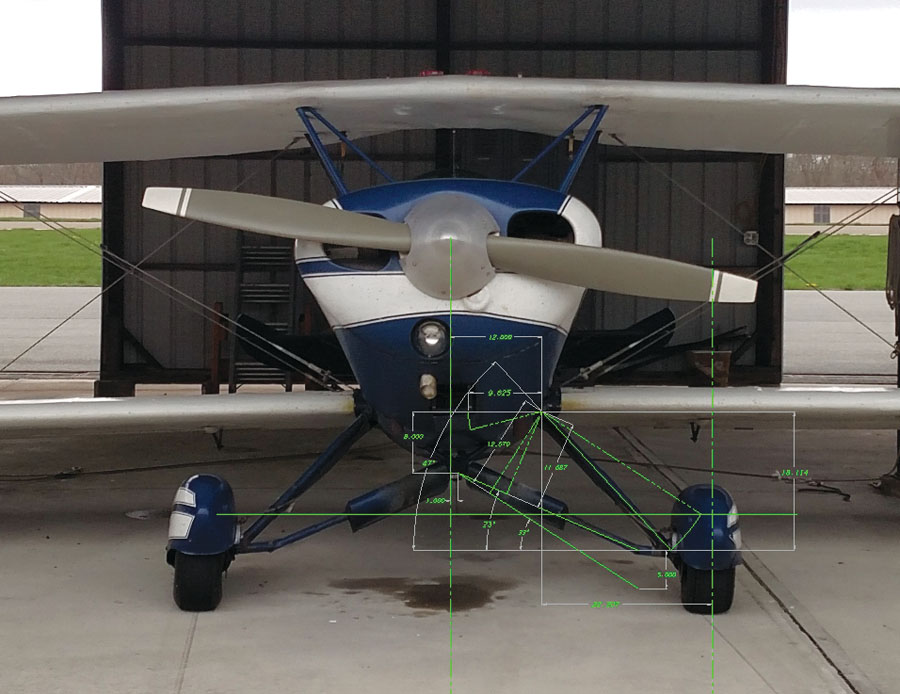
Front view with overlaid CAD layout. The plane is visibly sitting right wing low.
Working with CAD
For the first rough layout, I took the nose-on photo of the plane and imported it into my CAD system. I use KeyCreator (formerly known as CADKEY) in my day job, and its free-form direct modeling approach is a lot more suited to “blue-sky” thinking and preliminary design than the currently popular parametric history based modelers like SolidWorks and others. Scaling the photo to the actual dimensions of the aircraft, I laid some rough geometry over it to calculate the angles and loads for the shock struts. Wag-Aero didn’t have any load versus deflection information on their strut design, but taking a similar approach with a photo of the shock strut from their website and making some educated guesses on the components used, I decided there was a good enough chance it would work to go ahead and order them. They’re supplied long, to be cut and terminated according to the buyer’s needs. Once in hand I would know exactly what I had, and until I cut them, I could always return them if they weren’t suitable.
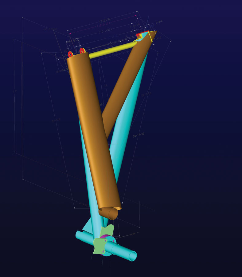
CAD model showing both gear versions. The earlier Starduster design is shown in brown, the new version in blue. The new version is much stronger.
While waiting for parts to arrive, I created a 3D CAD model of the original landing gear, as shown on the drawings. Welded aircraft structures are in many ways closer to blacksmithing than the precision machinery I normally work with, and the 1960s-era drawings I was working with left a lot to the imagination, but I finally figured it out. At the same time, I modeled the new design for the Starduster gear over the original on the same model to compare the two. Of course, the final parts won’t exactly match the CAD model after welding, bending, and hammering, but it helped to visualize things and generate cut patterns. I also printed it full size so I could lay the parts on the paper drawing to check them as I went along.
Refining the Design
Lines traced over a photograph are fine for the first approximation, but aren’t good enough for an accurate design, so it was time to get some real measurements. Borrowing a cherry picker from a friend, I hoisted the plane by the engine mount and removed the landing gear, then using plumb bobs and a level, I made careful measurements of the gear attach points on the fuselage. Unsurprisingly, they were close, but not identical, to the dimensions shown on the plans. Of particular importance was the fact that the pivot bolts on each side weren’t exactly in line. The misalignment wasn’t enough to interfere with the pivoting action, but enough to mean that the new gear would have to be welded with the same built-in misalignment. Whether it was always that way or due to wear and tear I don’t know, but the misalignment was exactly the same and in the same direction on both sides. This made it easier to construct a jig to build the new gear on. I had already made some brackets to bolt to a pair of heavy-duty jack stands, and attaching them in place of the landing gear, I lowered the plane back down and took the old gear legs home for further measurements.
Measurements made on the original gear legs at home agreed with the measurements I made under the plane, which was encouraging. I adjusted the CAD model to reflect reality, then refined the new gear model to be a blend of the old geometry and the new. Finally, I was ready to start cutting metal.
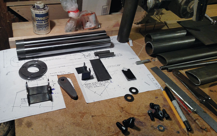
Some of the cut parts ready for fitting and welding. Premade “weld-on” axles were purchased.
Making Actual Parts
The first parts made were the small bits for the upper end of the legs, cut and bent from 4130 sheet. Next was the angle cut at the top of the front legs, which would set the angle that everything else had to match. I could have done it with a saw and grinder, but since I have a small milling machine, I set it up in a swivel vise and milled it at the precise angle. I then flattened the tube ends slightly to match the upper bracket length and tack welded them in place.
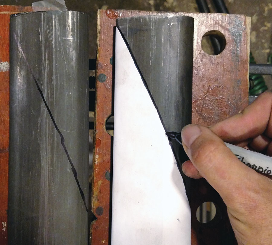
Tracing the cut line from the paper pattern.
The next parts to cut were the rear gear legs. There are rules of thumb to lay out and cut fishmouth tube intersections, but I instead used my CAD system’s surface unwrap function to generate a precise paper pattern. Cut out and taped around the tubes, I used the pattern to trace the intersection curve. After rough-cutting it with a cutoff wheel, I finished it with a disk sander and air grinder, laying the tubes together on the full-size print to check the alignment. Only a small amount of tweaking from the traced cut line was necessary.
Around this time I built the jig to match the attachment points on the fuselage. Four brackets were cut from aluminum angle and screwed to a piece of plywood with epoxy around the brackets to keep them from shifting. The next step was to cut the shape for the top of the rear tube. This was a bit tricky to cut, but I again used the mill to get the angle right.
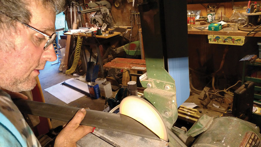
Grinding the cut line with a disk sander.
Finally, I was ready to put the gear leg together. After bolting and clamping the parts in the jig, I tack welded the small parts to the upper end, bent the cover plate, and brought the assemblies to a friend for finish welding. I’ll weld non-critical stuff myself, but I’m not a good enough welder for something like this. My friend Joe is, though, and he volunteered to TIG weld everything together for me. As TIG leaves a very concentrated heat affected area, all welds were stress relieved with a torch afterward.
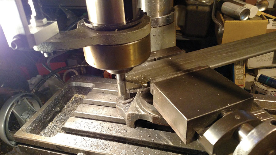
Angle cutting the streamline tube on the mill.

Cutting the notch in the flattened tubing for the upper bolt bushing.
With the upper ends welded, I returned to the jig to tack the tubes together at the lower end and fit the upper cross tubes. I again used a paper pattern from the CAD to trim the cross tubes, but this time I found it easier to freehand cut the rough fishmouth shape on the mill, then finish it with the hand grinder.
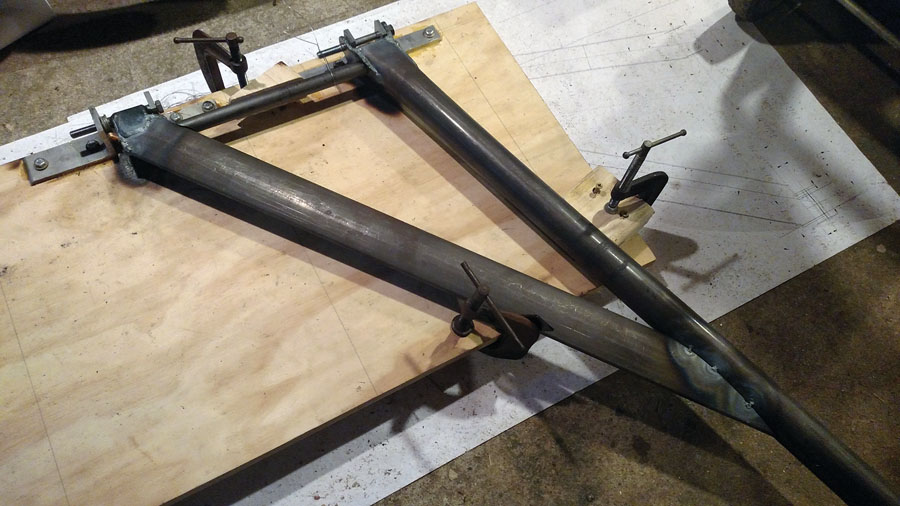
Parts in the jig for tack welding.
After tack welding the front, rear, and cross tubes together, I brought them to the airport to verify the fit on the plane before final welding. Another fit check on the plane to verify that nothing had moved during finish welding, and it was time for the trickiest part—getting the axles lined up perfectly. This had to be done on the plane in several steps. First was to measure the distance from the end of each leg to a point on the tail of the plane. I used one of the tail-spring mounting bolts as a reference point. There was a 3/8-inch difference, so I offset the axles slightly in the CAD model, 3/16 inch forward on one side and 3/16 inch aft on the other, to compensate before creating the flat patterns to cut the tubes. Once rough-cut with a Sawzall and ground close to the final line, it was time to head to the hangar with welding tanks, jacks, hand grinder, etc.
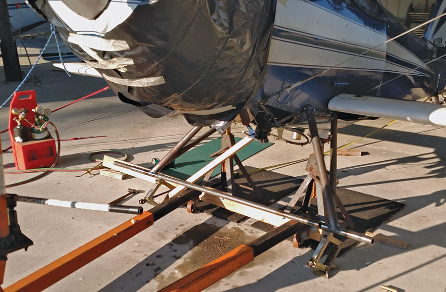
The axles have just been tack welded in place. Note the long tube through both axles to hold them in line during the process.
Working at the Airport
I had already cut a long piece of 1-1/4-inch tubing to slip inside the axles to hold them perfectly in line while welding. At the airport, with the plane suspended and leveled, and the axles resting on a pair of jacks, I lined everything up and checked the fit and alignment. It was nearly perfect, and the tubes cut to the CAD pattern needed only minimal touching up with the grinder before tack welding the axles to the legs. With the rear gusset also tacked into place, I turned my attention to the spring struts while waiting for Joe to finish-weld the axles.
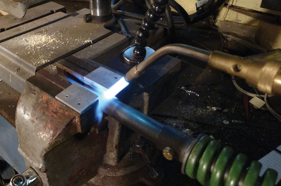
Heating the tube after flattening the end. The aluminum angles have radiused edges to protect the tube from the knurled faces and sharp edges of the vise.
Earlier, when the spring struts had arrived, I disassembled them to determine the working range and loads. I have access to a hydraulic press with a load cell at work, which made it possible to measure the actual spring rate since Wag-Aero was unable to provide this information. This confirmed that my guess about the spring used was close and that it should be suitable. The measured spring rate was 1600 pounds per inch with 1/8-inch (200 pounds) initial compression. Based on this, the struts would extend another 3/8 inch with the airplane sitting on the ground at full gross weight, so the struts would need to be cut 3/8 inch shorter than the measured distance. I was a little concerned about the short 1-1/4-inch travel of the spring compared to the original bungees, but the actual wheel travel is double that, and this type of strut is successfully used on many other aircraft.
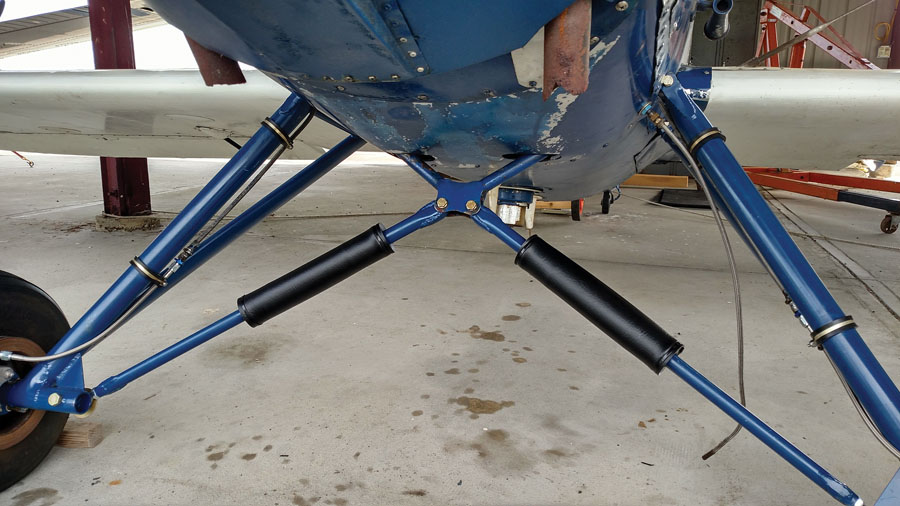
The spring covers in place on the gear. Yes, the exhaust needs some attention. The fuel tank vent hose still needs to be secured to the gear leg.
The tops of the bungee struts attached between two plates below the fuselage, and I duplicated that on the new spring struts. The bottom went into a fork cut on the end of the axle, and I initially planned to do the same with the new gear. But with the geometry finalized, the spring struts would better align just behind the axle, rather than on the axle centerline. The twisting moment on the axle would be negligible, and I considered that better than an out-of-plane load on the upper attach points. I wanted some adjustment anyway, not knowing for sure how the springs would behave. A swiveling ball rod end would give me the needed adjustment and compensate for any misalignment at the axle. MIL-SPEC rod ends are obscenely expensive, but similar commercial ones are far more reasonable. The -inch size I chose were made for racing and off-road vehicle suspensions, and rated over 16,000 pounds each, so I had no worries there. I was more concerned with the bolt holding the rod end to the axle, which is why I chose the largest one I could fit in the tube end. After a rough stress analysis to satisfy myself that the -inch AN bolt in single shear would be adequate, I ordered the rod ends, along with threaded weld-in tube plugs to fit the lower end of the struts.
At the top of the strut, I had to flatten the 1-inch tube to fit inside the attach plates. Squeezed in a vise to 3/4 inch and heated with a torch to relieve stress and limit springback, the end was then notched to fit the bolt bushing, and the ends ground back at a 60-degree angle using the disk sander. A cover plate was bent, and it was all welded together. The lower end would be cut to the final length after making the measurement during the final fit check of the gear on the plane.
The plane is finally resting on its wheels again. The brake calipers still have to be mounted, and the wheels are being held on with a temporary hack while waiting for the proper axle nuts to arrive.
Almost Finished
With the axles welded, it was time for one last alignment check on the plane and, at the same time, to get the final dimension for the spring struts. I had already drilled the hole in the axle for the lower bolt bushing (using a 3/4-inch OD bushing, in case I needed to drill it in the future for a larger bolt), but it wasn’t yet welded in place, so I could still slip the long alignment tube through. As it turned out, the alignment tube would no longer slip all the way through the axles. Presumably, there was some slight distortion from welding, but by cutting the tube shorter, I could get about six inches in from the inboard side, which was enough. The alignment was still good, and after measuring for the spring strut lengths (not quite the same on both sides), I cut the tubes, prepared reinforcing plates, and brought them back to Joe for the last bit of welding.
As the airplane is currently in an open hangar, I elected to protect the tube interiors with linseed oil. A small hole was drilled in each end of the leg tubes and oil injected into the tubes with a syringe. After sloshing them around to coat the entire tube, I set them aside to drain overnight. That was a rather messy job. After plugging the holes with drive screws coated with epoxy, I cleaned the excess oil off the outside with solvent and sandblasted the gear to get it ready for paint.
Since the spring struts couldn’t be completely sealed, I left a 1/16-inch hole at the bottom to drain any water that might get in. I debated how, and to what extent, to paint the spring struts. With the upper end flattened and welded, they couldn’t be completely disassembled, and not wanting paint on the sliding surfaces, I painted them assembled with the spring portion masked off. To avoid scratching the paint during disassembly (which required clamping them in a vise), I took them apart one more time to coat the sliding surfaces with white lithium grease before painting.
Since I didn’t need much paint, I took a piece of the fabric to the local NAPA auto parts store, where they can match and mix up automotive paint in custom colors and put the paint into a disposable spray can. I also got two cans of primer: one of standard primer for the steel parts and one of self-etching primer for the traditional Starduster aluminum gear fairings or “spats,” which I would fabricate later. One can was barely enough for the gear, so I had to go back for another can for the spats.
Finally, everything was ready to put the plane back on its wheels. With the plane in an open hangar, I was nervous about leaving it supported on the jack stands for an extended time. Even with the plane tied down securely and the jack stands sitting on thick rubber pads, it was much less forgiving than tires and sprung gear. I had originally expected to have it off the gear for no more than a week or so, but life intervenes, and it was now three months later. Fortunately, the weather had been good.
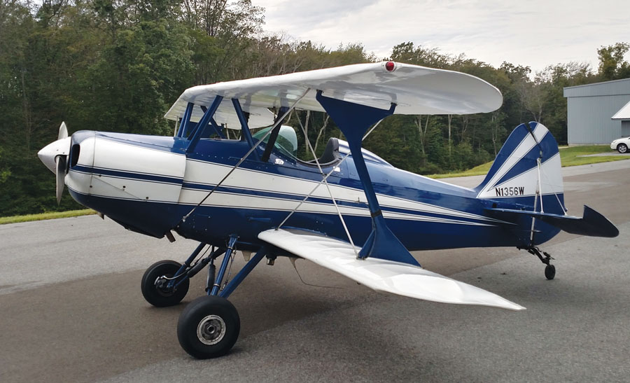
Back on the ground at home after successful test flights.
Frustration
When packing everything up to take it to the hangar in the morning, I discovered the axle nuts I intended to reuse had a 1-1/2-16 thread, as did the original axles. Unfortunately, the new axles had a 1-1/2-12 thread. Grrrr. And, of course, it’s not the kind of thing you can find locally—believe me, I tried! I put it all together anyway, and after slipping the wheels onto the axles, the plane was actually sitting on its wheels again. To temporarily hold things together, I cobbled up a hack using some threaded rod, a piece of tubing, and some aluminum bar. Not good enough to fly or even taxi, it was good enough to roll the plane around and check the tracking. It rolled easily (unlike before), the initial spring extension was exactly the 3/8 inch I had calculated, and when I hoisted the plane up 6 inches and dropped it, everything moved properly and nothing broke.
The axle nuts weren’t the only remaining issue. With the longer gear, the brake hoses weren’t long enough. I wanted to replace them all the way back to the parking brake valve, but access in the front of the cockpit was so difficult, it was much easier to add an additional piece of hose at the caliper end with a coupling. The additional length would also allow a neater installation inside the spats.
While waiting for parts to arrive, I finished cleaning things up and replaced the cowling and other fairings I had removed. I also took some measurements and made some adjustments to the rod ends to get the plane perfectly level.
I was still waiting for the proper axle nuts, kindly sent by Starduster guru Dave Baxter, but I replaced the temporary hack with modified hex nuts from an industrial supplier. With those in place and the calipers mounted, the plane could finally be taxied. What a pleasure…it tracked straight, not nearly as squirrely as before, and the new gear soaked up the bumps just fine while bouncing over the rough end of the grass alongside the runway. The next evening, I installed the new hoses, bled the brakes, and tidied everything up.
The last task before flying was to finish making and installing the spring covers. These consisted of plastic disks, cut in half, then drilled and tapped for screws to hold them together once in place on the spring struts. A flexible vinyl cover was secured with zip ties in grooves on the outer diameter of the disks. The upper disk is clamped to the upper tube, while the lower one is a clearance fit to allow the tube to extend.
Four months after the problem was discovered, the Starduster was ready to fly! As noted during taxi testing, it tracked straight as an arrow, and the takeoff was effortless. Before landing on the paved runway at Chester (Connecticut) Airport, my home field, I flew to the grass runway of nearby Salmon River Airfield for the first landings. It took some time to get used to landing the plane—it’s no Cub—but it wasn’t the holy terror it was before.
All that remained was to mount the wheel pants and fabricate the spats traditionally used on Stardusters. Not only do they give the plane a distinctive look, but being removable, they won’t hide any problems like the fabric cover did on the old gear.
Unfortunately, that never happened. Only a few weeks and 8 hours’ flying time after finishing the gear, engine problems led to a forced landing in what looked like a big, beautiful hayfield from the air, but turned out to be a marsh with tall clumpy grass. I walked away with no injuries, but the airplane (including the new landing gear) was seriously damaged. Now I have a somewhat larger rebuild project.


Sorry to hear about the mishap/forced landing. Thankfully you’re okay and still have the (considerable) skills to repair your ship.