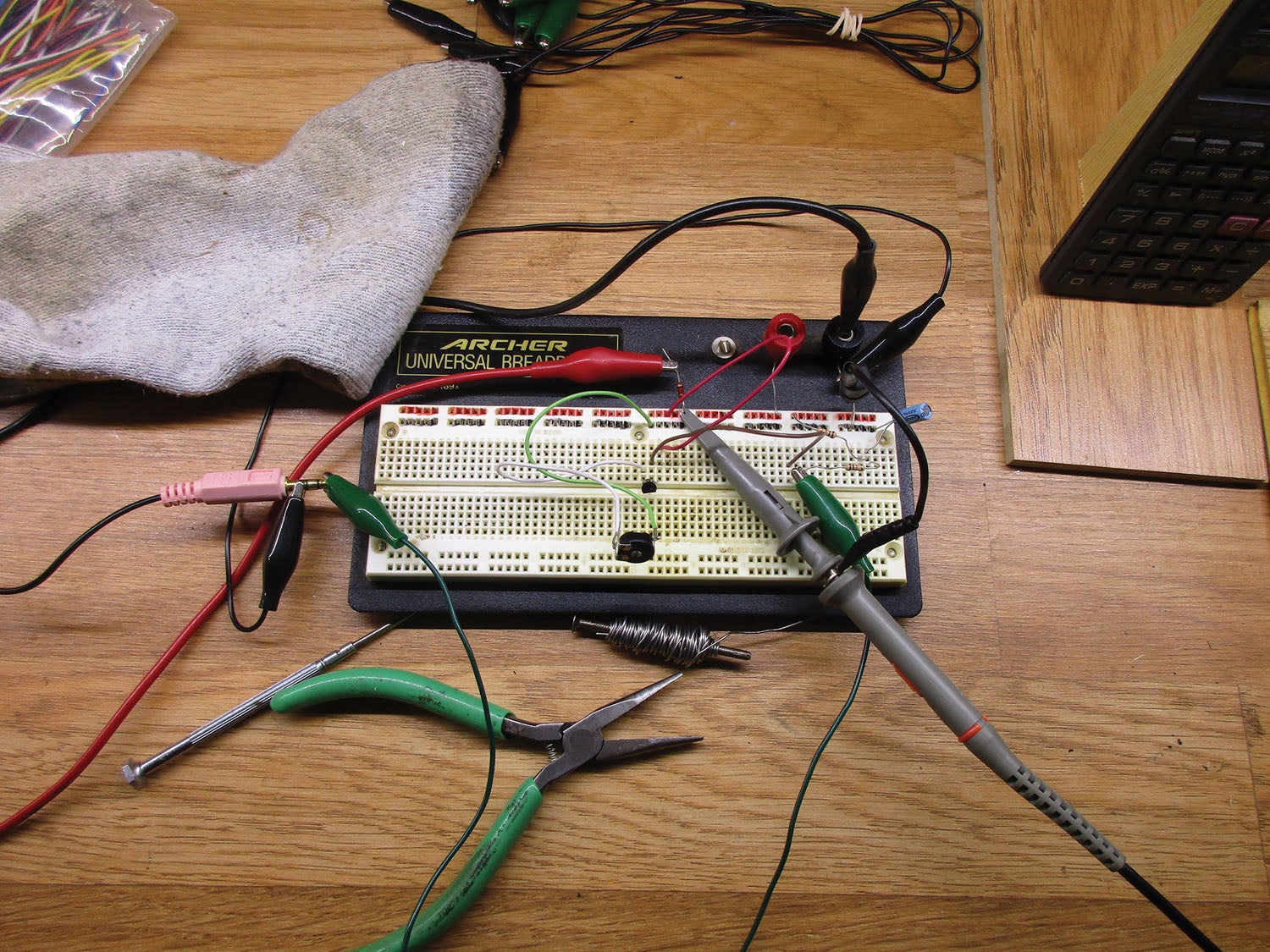
Otto von Bismarck said that if you enjoy sausage and law, you should never watch either of them being made. I will add to that list electronic circuits when first trying to get them to work. We generally call these circuits “breadboards” because back in the vacuum-tube days, these trial circuits were actually soldered together and bolted to kitchen breadboards. The image you get this month shows the breadboard circuit for this project—not that I would recommend this construction for permanent installation.
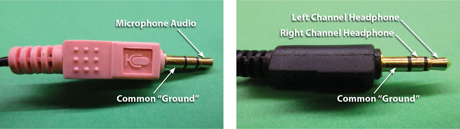
A short time ago, I got an email asking if there was an easy way of converting a computer headset for aircraft use. I asked what “easy” meant, and the answer was how to wire that little computer plug to the big aircraft plugs directly. That just isn’t possible. Let me elaborate.
Way back in 1917, the first air-to-ground transmission was accomplished in Morse code. A year or so later, we made the great leap to transmitting voice. The problem was that the cutting-edge technology of the day was using a microphone consisting of a couple of tin can lids squeezing a small sack of ground-up coal between them…the carbon microphone. When your voice hit that can lid, it jostled the coal around and thus the resistance between those two can lids varied in time with your voice. Thus was born the carbon microphone.
You should recall that it was about this time that Bell’s revolutionary invention—the telephone—was starting to be widely implemented throughout the world. For the telephone to work, you needed two things. One was that carbon microphone that translated the transmitter’s voice into a change in resistance, and the other was an electromagnet near the receiver’s ear that would vibrate another tin can lid with those same voices making sounds in the receiver’s ear.
Since airplanes at the time could be counted in dozens and the telephones being installed counted in millions, it seemed reasonable that aircraft would adopt microphones and earphones being produced by the millions for their very few aircraft radios.
(Just as an aside, since the broadcast radios of the day were using amplitude modulation [AM] and frequency modulation [FM] wouldn’t be invented for another couple of dozen years, aircraft radios were then and still are using AM as the mode of operation.)
So, aircraft radios today require carbon microphone circuitry for the transmitter and electromagnets for reception. Not only that, but we are stuck with aircraft radios designed using the old telephone microphone impedances of 150 ohms and 300-ohm receiver impedances (slightly modified).
Computers for the home didn’t really take off until the 1980s, and by that time we had much better microphones to pick from. Specifically, we had the capacitor microphone, which consists of a very small metal plate with a very small metalized plastic film separated by air from the metal plate. The voice jiggles the plastic film, which changes the capacitance between the plate and the film, then do a little electronic wizardry, and bingo, a capacitor microphone. Rugged, sensitive, and almost impossible to break. But they don’t produce anywhere near the voltage that a carbon microphone produces, and they are much higher impedance than a carbon microphone.
But transistors are such neat little devices in that they can take the tiny little signal from the capacitor microphone and convert it into a signal strong enough to mimic a carbon microphone while giving us the impedance match we need in the bargain.
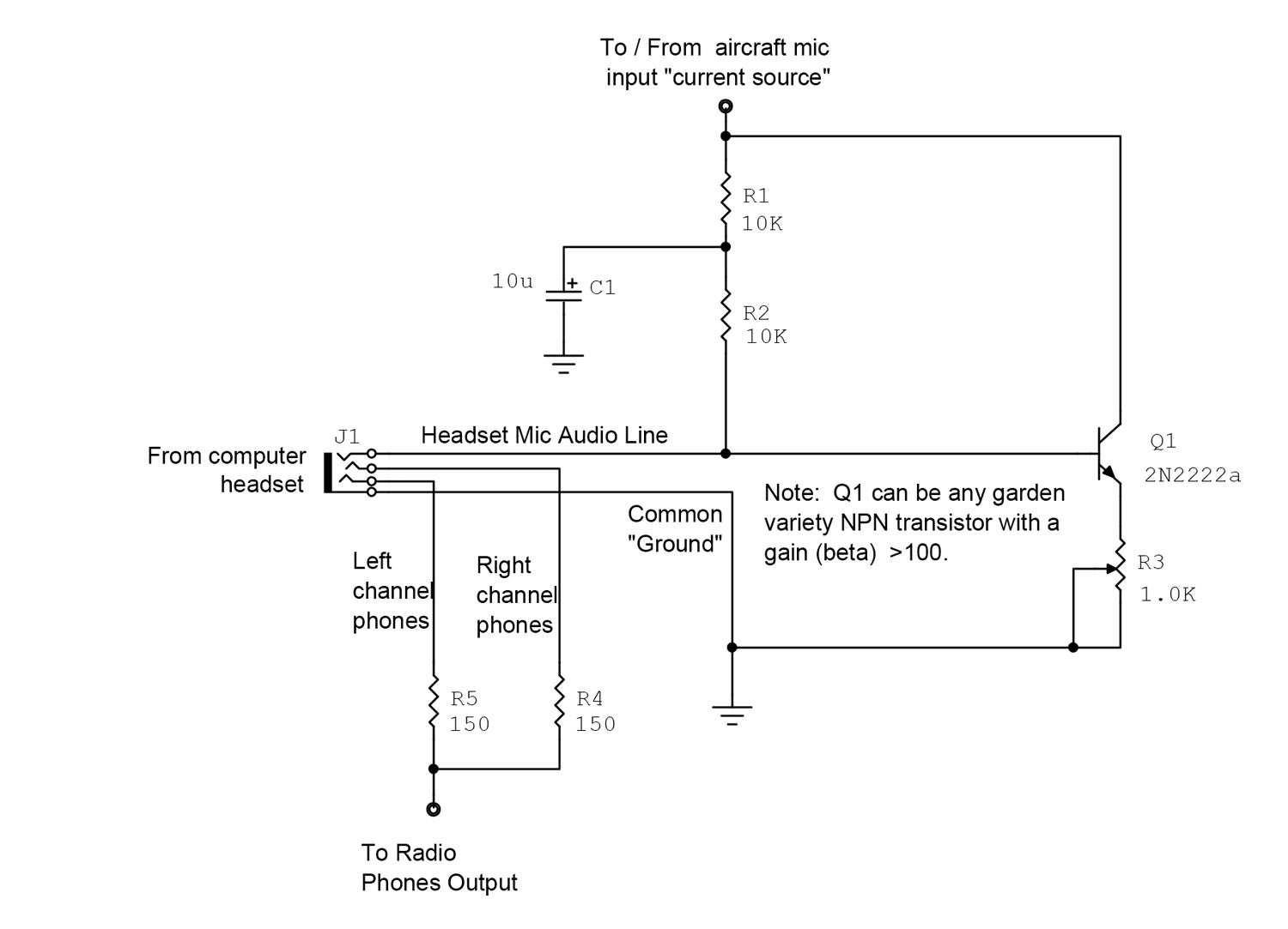
The circuitry inside the radio consists of a constant current source (either a relatively large-value resistor or a transistor in a current source configuration) that provides somewhere between 5 and 15 milliamperes of direct current from the 12-volt power source. We can use that current source to power both the capacitor microphone and a single-stage transistor amplifier to get the required voltage and current to simulate that carbon microphone. You will see this current called several names: phantom power, mic bias current and several lesser used terms. But the schematic diagram shows how this circuit takes the mic bias current and powers the microphone and transistor simultaneously.

There is a variable resistor in the emitter circuit of our transistor amplifier. The standard specification for an aircraft microphone is 150 millivolts RMS (which is about 500 millivolts peak to peak). This resistor is adjusted to provide this amount of voltage from your voice when you talk into the microphone. If you don’t have access to a way of measuring this voltage, it is possible to plug a known good microphone into your aircraft radio and use a portable radio with a friend at some distance from the aircraft. Use the known microphone as a test and then plug your modified computer microphone into the radio and adjust the variable resistor for the same “loudness” from the remote receiver. You may, if you like, adjust that resistor for the correct volume, take it out, measure it and put a fixed resistor in its place.
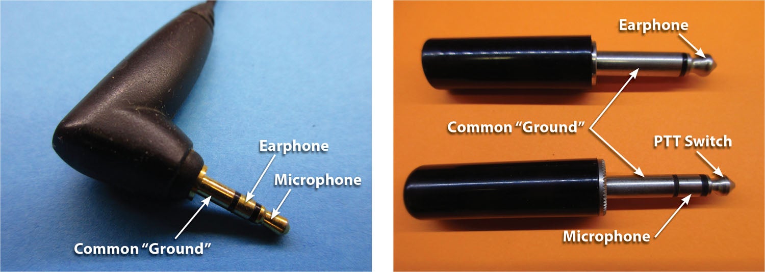
Thus far we have taken care of one half of the headset. It’s now time to discuss the other half…the earphones.
Back up a few paragraphs where I said the earphones that Bell used were 300-ohm devices. That’s fine, but a telephone only has one earpiece. We need both ears covered and that gives us two choices: We can run two earphones in series to give us 600 ohms or in parallel to give us 150 ohms. Originally we ran them in series because that puts less of a load on the radio. What we found in the mid-1960s (and specifically at that little unpleasantness in Vietnam) is that when one earphone broke a wire, it opened the circuit and the whole headphone went dead. If we ran them in parallel, then one earphone would be off, but the other one would still work. We then redesigned our radios to drive four sets of earphones at 150 ohms, which works out to 38 ohms, four sets of 150 ohms in parallel.
That’s all well and good, but the computer earphones are 32 ohms—each. Even worse, the stereo computer ’phones have 32 ohms each side, and if we drive them in parallel, that’s 16 ohms. Four of those at the same time on the radio means we have to drive a 4-ohm load. Most radios won’t do that. But there are a couple of solutions.
One: We pick which ear we want to listen to and only use one of the earphones.
Two: We use a series resistor to up the impedance of the headphones. The downside to this is that it cuts the volume of the headset down. Most of today’s radios have enough reserve volume to blast standard aircraft headphones into the threshold of pain. That means if somebody is using a normal aircraft headphone and we adjust the radio volume up, it will be way too loud in their aircraft headphones. And then we can play around with resistor values to cut their headphones down to our modified computer headphone level. Kind of like rubbing your tummy and patting your head at the same time.
Enough of this. Next month we’ll have a complete report on the small HOG solar cell to keep the aircraft battery happy. Two versions. Easy circuitry. More later. Until then…Stay tuned…


s")


Hi Jim Weir Love your columns… reminds me of the days of Popular Electronics ! Having worked for AT&T for 35 years I thought you might want to know what the 3 parts of a telephone cord plug are called . You got 2 right (“tip” ; then “ring” ) the third is called a “sleeve”! FYI . Keep them coming… & Tnx Neil Nisita
Comments are closed.