The size and planform of the ailerons are set by the roll-control power needed to meet flying qualities and maneuvering requirements. Once the designer has defined these parameters, it’s time to pay attention to the design details of the ailerons and the control forces needed to fly the airplane.
There are a wide variety of aileron design concepts and devices to control aileron hinge moments. This month we will take a look at the three most common approaches.
Plain Aileron
The earliest form of aileron is a simple surface hinged directly to the leading edge of the movable surface. This is called a “plain aileron” and it remains in common use today.
Plain ailerons typically come in two varieties: In the first, the hinge is placed vertically halfway between the upper and lower surface of the aileron, and the leading edge of the aileron is formed into a segment of a cylinder so that the deflected aileron presents a smoothly curved surface to the air at the hinge line.
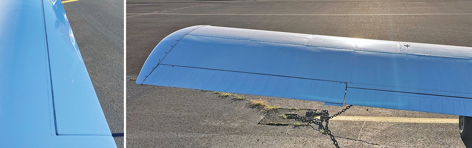
The second type of plain aileron, which is commonly used on metal airplanes, is to hinge the aileron with a piano hinge connecting the trailing edge of the upper wing skin to the leading edge of the aileron skin. Piano-hinged ailerons are light and simple, but they must have a significant gap between the wing and aileron on the lower surface in order to let the aileron deflect downwards. This gap costs drag, but it is possible to partially fair the gap with a properly designed seal.
The primary advantages of plain ailerons are that they are mechanically simple and it is relatively easy to seal the aileron gap aerodynamically to minimize drag.
On the negative side, plain ailerons do not have any form of aerodynamic balance to control hinge moments and, accordingly, for a given aileron planform and area, they have the highest hinge moments.
The total hinge moment is a function of the aileron chord and area, and the airspeed of the airplane. The stick forces the pilot must exert to fly the airplane can vary dramatically depending on the speed at which the airplane flies and the roll-control power needed to meet roll maneuvering requirements. For many airplanes the hinge moments generated by plain ailerons are completely acceptable and a plain aileron is a good design choice.
Aerodynamically Balanced Aileron
As airplanes developed, hinge moments became a serious design issue. Airplanes got bigger and faster, and reached the point where stick forces required to control the airplane using simple plain-flap control surfaces directly moved by the pilot’s strength became too high for a single pilot to comfortably handle.
This manifested in two ways. For transport aircraft and bombers, the airplanes and their control surfaces simply got so big that the forces exerted by the control surfaces became too large to handle.
In the fighter world the airplanes did not get much bigger, but speed increased dramatically. The WW-I Sopwith Camel had a top speed of 113 mph while the P-51D Mustang of WW-II had a top speed of 440 mph. Aerodynamic force (dynamic pressure) is a function of airspeed squared, so the P-51 experiences 15 times the aerodynamic force per unit area as the Camel. The issue was particularly acute for fighters where roll rates and roll agility were of critical importance in air combat.
As aileron forces rose, designers came up with new design concepts that reduced aileron hinge moments dramatically. Using a combination of hinge placement and nose shaping, these new designs enabled a single pilot to control very large airplanes like WW-II bombers and very fast airplanes like WW-II fighters with a mechanical control system.
Moving the hinge line aft so that some of the area of the aileron is ahead of the hinge places the pivot point closer to the center of pressure of the aileron, thus reducing hinge moment.
When the hinge line is aft of the leading edge of the aileron, the nose of the aileron moves up and down as the aileron deflects. If the nose of the aileron unports from the aileron cove and protrudes into the airflow, it can generate significant aerodynamic force that tends to drive the aileron in the same direction as the initial deflection.
The two major types of offset hinge ailerons differ in how the hinge is placed and where the aileron nose goes when the aileron deflects.
Frise Aileron
The first type of balanced aileron was invented in Britain by Leslie George Frise and is accordingly named after its creator.
On a Frise aileron, the hinge line is aft of the leading edge of the aileron and on, or slightly below, the bottom surface of the aileron. When the aileron is deflected trailing-edge up, the nose moves down, out of the cove, and is exposed to the outer airflow. The force on the nose tends to drive the aileron more trailing-edge up. This force is opposed by the force on the portion of the aileron aft of the hinge, and the overall hinge moment on the aileron is determined by the balance between the two forces.
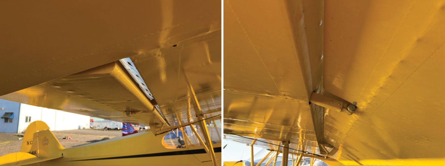
When a Frise aileron deflects trailing-edge down, the nose moves up into the aileron cove and is shielded from the airflow. The restoring moment generated by the portion of the aileron that is aft of the hinge line remains. This means that the hinge moments by the two ailerons are asymmetric. The down-going aileron has a higher restoring moment than the up-going aileron.
In extreme cases, it’s possible to rig a set of Frise ailerons so that the up-going aileron is actually unstable and has a hinge moment that tends to increase its deflection. This moment is opposed by the restoring moment of the down-going aileron; since the two ailerons are linked, one going up and one going down, the complete aileron set is stable and has a low net hinge moment. At least one WW-II fighter used this setup to keep the stick forces low and let the pilot rapidly roll the airplane at high airspeed.
The danger of going this far with Frise ailerons is that if an aileron linkage fails, the aerodynamic forces on the nose will drive the loose aileron to the stop, trailing edge up. Most Frise-aileron setups are less extreme, so the up-going aileron is stable about the hinge line.
Simple Offset Hinge
The second concept is a simple offset hinge aileron. The primary difference between an offset hinge aileron and a Frise aileron is that the hinge of the offset hinge aileron is midway between its upper and lower surface, and the top of the cove is open so that the nose of the aileron can unport on both sides of the wing. Unlike a Frise aileron where the nose of the trailing edge down-deflected aileron goes into the cove, the nose of the down-going offset hinge aileron extends upward into the airflow over the top of the wing and generates force that alleviates the hinge moment.
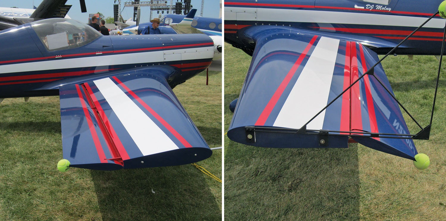
Offset hinge ailerons can be tailored to have very low hinge moments even at higher speeds and high deflections. They are a good choice for an airplane that needs to develop high rates of speed and where stick forces are of importance. The disadvantages of offset hinge ailerons are, first, that the combination of the open cove and the offset hinge cantilevered aft of the wing spar is heavier and more mechanically complex than other aileron systems, and second, that in order for the ailerons to work aerodynamically, the cove must be open, and there is no aerodynamically acceptable way to seal the gap.
This means that an offset hinge aileron system will be both heavier and have higher drag than either a plain aileron or a Frise aileron.
Because of these factors, offset hinge ailerons are commonly seen on aerobatic airplanes and rarely used on other types.
The choice of aileron type for the designer is a tradeoff between cost, weight, aerodynamic drag and control forces. Sometimes the right answer to the question is not clear or unequivocal. Occasionally, designers even change their minds midstream. One example of this is the Piper Warrior. The original Warrior had Frise ailerons as a feature of the new tapered higher aspect ratio wing that replaced the earlier constant-chord Hershey bar wing of the previous model Cherokee. A few years into the production run, Piper revised the airplane. They eliminated the Frise ailerons and replaced them with plain piano-hinged surfaces. They concluded that the airplane would have acceptable flying qualities with simpler lower-cost plain ailerons and took advantage of the opportunity to reduce the cost of producing the airplane.


