![SR-1 cowl being integrated with spinner and cooling ducts. The cowl is assembled to itself/to the fuse primarily with countersunk #8 screws. [All images credited to Eric Stewart]](https://www.kitplanes.com/wp-content/uploads/2026/09/1KP.jpg?w=696)
The cowl for the SR-1 was the last set of molds to be produced for the project. I had originally planned to use a UL Power engine but by the time I began work on the firewall forward (FWF) it was clear that a modified Rotax from Edge Performance in Norway would provide superior power at lower weight. (The Rotax is a great engine but folks considering a switch in an airplane designed for an air-cooled powerplant should be aware that the cooling system is significantly more complex, to say nothing of the impact on center of gravity). The downside was not only a significantly more complicated FWF, but I would also need to redesign the entire cowl.
Fortunately I was aware that this might be a possibility when I originally designed the fuselage, and so terminated the fuse at the firewall with a fairly flat curvature that allowed for leeway in extending those curves forward around the engine without encountering any kinks or reversals of curvature.
One old school method of fabbing a custom composite cowl involves mounting the engine, wrapping it in a protective sheath of plastic, and adding blocks of foam and/or pour foam. The cowl is then rasped down to the rough dimensions and final sanded to a set of templates. Mike Arnold’s videos of fabricating the AR-5 and -6 both illustrate this approach and are available on YouTube.
Computer modeling allows us to do this virtually, with the benefit that we can easily make changes and tweaks along the way and avoid the associated labor and mess. Edge Performance was able to provide me with a CAD model of the 912STi, which I imported into the master assembly of the raceplane. (A non-commercial version of Solidworks is available to EAA members for a very reasonable price; I highly recommend it.) I then added components like the engine mount, intercooler, radiator, oil cooler etc., and manipulated all these items – along with the outline of the cowl – until everything fit. It was a very iterative process – often making space for one item caused a packaging problem elsewhere. It’s a bit like solving a Rubik’s cube – solving one side just messes up the last side you solved.
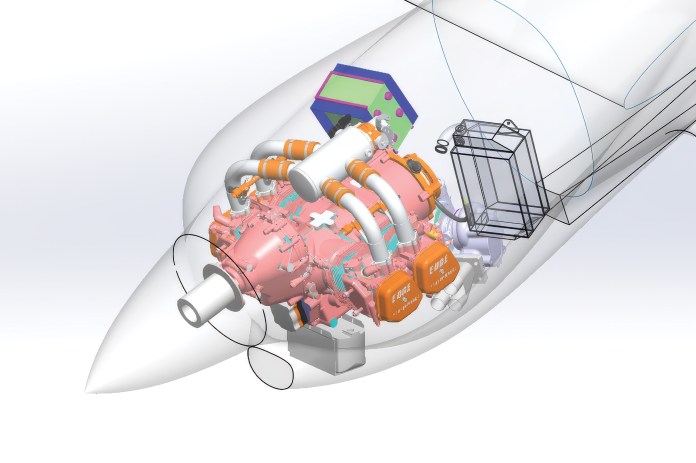
CAD Solidworks model of the Edge Performance 912STi was imported to the fuselage assembly, along with items like the intercooler and radiator, to check for packaging and interference. The CAD allows cross section viewing and controlling part transparency, which is helpful in identifying/avoiding interference between the cowl and various components. 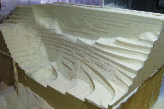
Bottom right cowl in the CNC after the roughing pass. 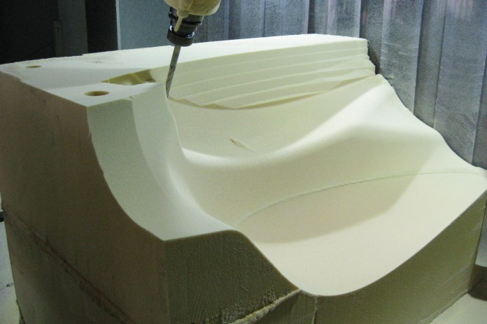
Finish pass almost complete. 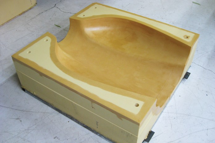
Top cowl showing holes for alignment pins, and epoxy coat. Thinned epoxy is brushed on the mold surface, as well as corners/edges of the mold. This is for durability, as the mold foam is quite light (6lbs per cubic foot); the resin soaks in and toughens the surface of the mold. 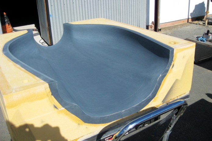
Top cowl mold being sanded smooth after being sprayed with Duratec. 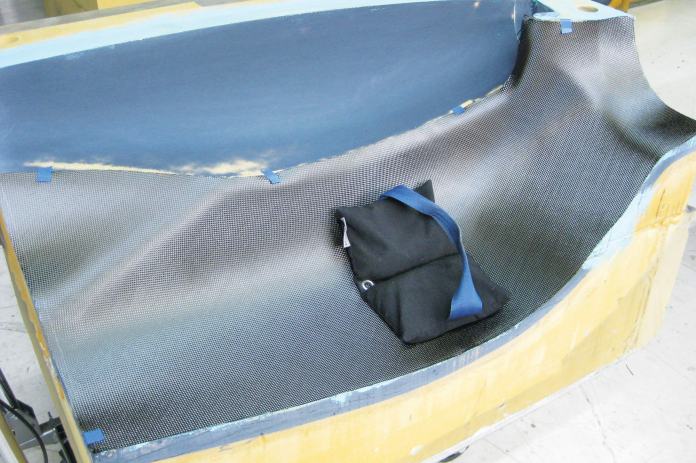
Checking the fit of the carbon cloth template before layup. 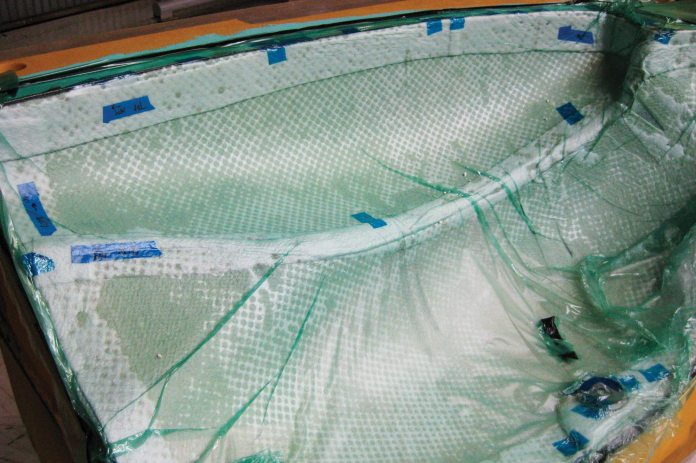
Part after vacuum bagging. 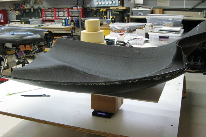
Weighing the part immediately after bagging (ie, no trimming) to check the fiber:resin ratio. I typically aim for 60:40. 50:50 is OK but unnecessarily heavy. Over 65:35 and you risk having areas with insufficient resin, in my experience.
It’s a tight package to be sure. In particular, the exhaust pipes and heat exchangers all have locations that come in close proximity to the cowl. In these instances, my rule of thumb was to maintain 0.75” clearance. 0.50” or even less in some cases would have been fine, but I wanted to allow some margin of error. In the end the model was quite accurate and my clearances are all .65” or greater. Note that this is a Rotax engine; clearances for other types of engines should reflect how much vibration, “wet dog shake,” or engine sag under g-load are expected. Be especially careful of proximity to hot components like the exhaust system, which may require additional heat shielding to avoid damaging the composite cowl.
The following outlines my approach to fabbing the cowl. To be clear, there are lots of ways to approach cowl design. The following is what worked best given my design goals (minimal weight, integrated heat exchanger ducting, sealing, and serviceability, to name a few).
Once I had the OML (outside mold line – i.e., exterior) of the entire cowl designed, I needed to determine how the cowl would be split as well as joined/fastened together – this would guide how I designed the molds. I considered a top/bottom, left right, removable lower intake, and more. In the end, it was clear that short of removing the prop, the bottom would need to be assembled as left and right halves. Due to the ducting requirements of the radiator and intercooler though, I still needed to be able to access those from above, so in the end only the bottom of the cowl was split left/right. The top is a traditional lid.
Likewise with the fasteners, you have a range of options – screws, dzus or piano hinges. I initially leaned towards piano hinges everywhere (they yield a nice consistent gap, and no pillowing that can sometimes happen with screws) but ultimately for various reasons (weight, degree of curvature, time) I used screws everywhere except the bottom left/right join. There are endless discussions on the online forums about which is best, but the fact that all are common tells you that all generally work fine, and it often comes down to preferences for weight, budget, and fit/finish. It’s best to figure this out early on, since you may need extra layers of carbon (or glass) at screw holes in order to build up the necessary depth to allow for countersinking.
Once the shape, split lines and fasteners were figured out, I created models of the female molds. For the wing and fuselage molds I had bonded tooling foam to steel frames. Based on discussions with my friend Paulo Iscold (professor of aerodynamics at Cal Poly, who built the current record holder in this class), who cut the molds on Cal Poly’s five-axis Haas, I eliminated the frames and simply bonded the blocks of foam to the router table with Bondo. In comparison to the wing and fuselage molds with are long and required subsequent jigging and assembly (and therefore benefited from the rigidity of the steel frame and the ability to bolt and weld multiple frames together for assembly purposes), the cowl molds are standalone parts requiring no subsequent assembly; additionally they are rather blocky in shape and thus there is little concern for warpage or bending. Ultimately the cowl was created with five distinct molds: upper cowl, lower left, lower right, cheek extensions, and exhaust tunnel.
In previous molds I have either used the double bag method (see my Sept 2017 article in KP) or a resin wipe followed by mold release wax + PVA to release the mold. For the cowl molds I used Duratec 7701 after the resin wipe. This was easy to apply but sure stinks. The Duratec was sanded with 220 followed by red scotch brite (3M 7447) to achieve a smooth surface. Imperfections and the odd pinhole were filled with putty (3M 05096 acryl putty). Release was 3 coats of mold wax (Partall Paste #2) followed by spraying with PVA (Fibre Glast 13).
I can’t recommend a particular layup schedule, as this depends on the degree of curvature in the cowl, aerodynamic loads, use of core (or not), service temperature, etc. Because the SR-1 cowl is composed everywhere of compound curves and the only flattish panel-like spot is the top aft cowl, I chose to not use core. While the individual cowl parts are quite flexible alone, when assembled the cowl is extremely stiff. I used extra layers of reinforcement along the screw lines (but also later added pad ups for countersinking – see below). As compared to the rest of the airplane which is primarily fabricated with MGS 285 resin, all FWF components, including the cowl, use PTMW 2520, a high-temp resin system. While it allows service temps of 300+ F degrees, it also requires postcuring at these temps, so an oven capable of 350 deg F, and large enough to hold the parts, is required.
Once all the cowl items had been fabricated and postcured, the next step was to fit the top cowl. At this point the engine was mounted, and the spinner backplate served as my x/y/z coordinate reference. I therefore 3d printed a proxy backplate support jig (I did not have the actual backplate yet) that mounted to the engine prop flange, and this set the exact position of the front of the cowl. I then trimmed the aft edge to the firewall joggle where the cowl attaches and match drilled and cleco’d the top cowl to the fuse. The top cowl also has a horizontal joggle that sets the join line with the lower cowl. With the top cowl cleco’d in place and supported at the front by the 3d jig, I now had the edge references necessary to trim the lower cowl.
First though it was necessary to join the lower left/right cowl. The lower centerline was trimmed, and the individual lower left and right molds were clamped together. The parts were inserted, aligned, and a carbon fiber piano hinge bonded along the centerline. I fabricate these piano hinges in a set of custom aluminum molds and they are quite a bit of work to make, so I tend to only use them in places where I expect to see higher performance requirements on the hinge due to loads, temperature or vibration – all of which are issues for this application. (I have done pull tests comparing the carbon hinges to extruded aluminum hinges of the same dimensions and they are equally strong, so the real advantage of the carbon hinge is a slightly lighter hinge, and a better bond to carbon substrates.)
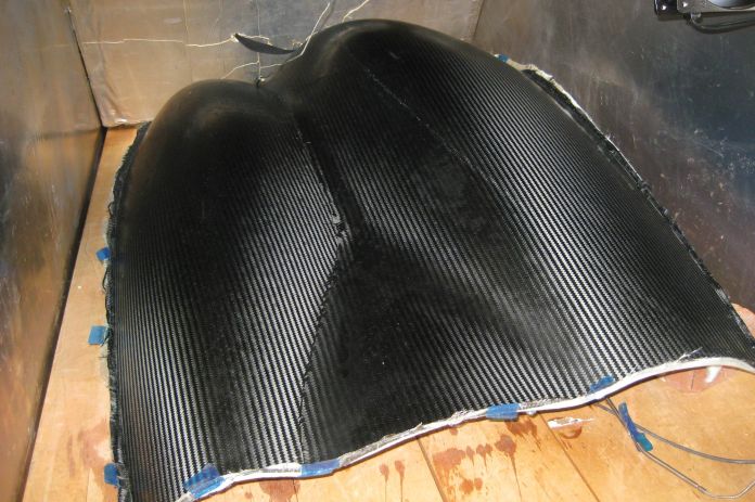
Lower left cowl in the oven for postcuring. 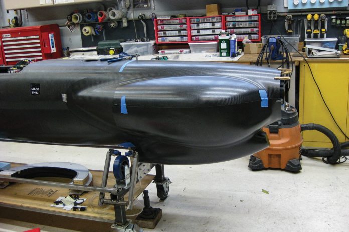
Once all the parts are fabbed, the next step is to mount them to the existing fuse and trim them to the fuse and each other. Clothespins at the front hold the top cowl to a 3d printed jig that represents the spinner backplate (I did not yet have the backplate at this point). 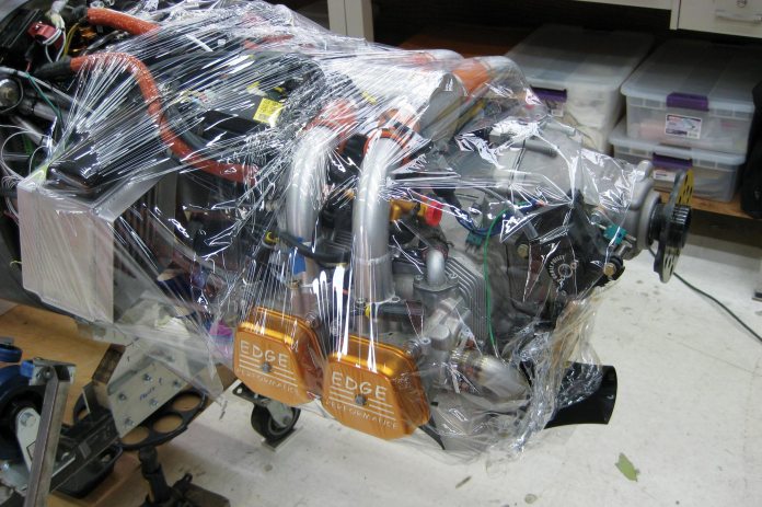
The engine is wrapped in plastic to protect it from any dripping epoxy while fitting the cowl with liquid shims. 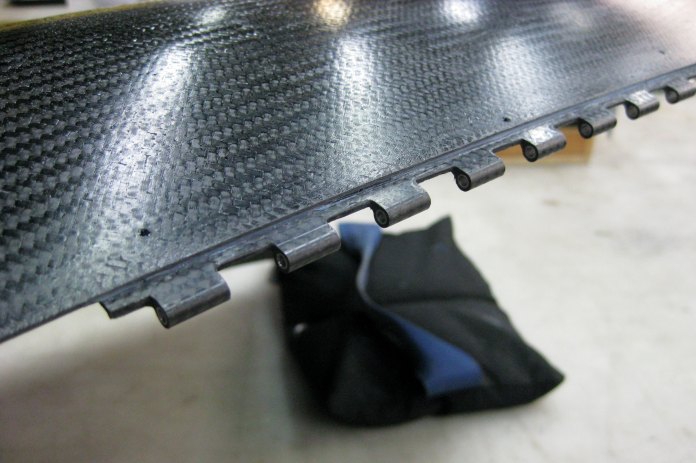
Carbon fiber piano hinges join the lower left and right cowl halves. Everywhere else the cowl assembles with #8 screws and nutplates. 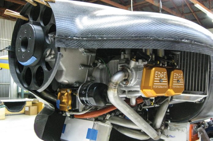
The joining flange for the top/bottom cowl. Left picture is before liquid shim, right picture is after. Note how the liquid shim registers the features of the upper shim, allowing it to exactly lock in place when the two are screwed together. 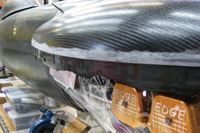
The joining flange for the top/bottom cowl. Left picture is before liquid shim, right picture is after. Note how the liquid shim registers the features of the upper shim, allowing it to exactly lock in place when the two are screwed together. 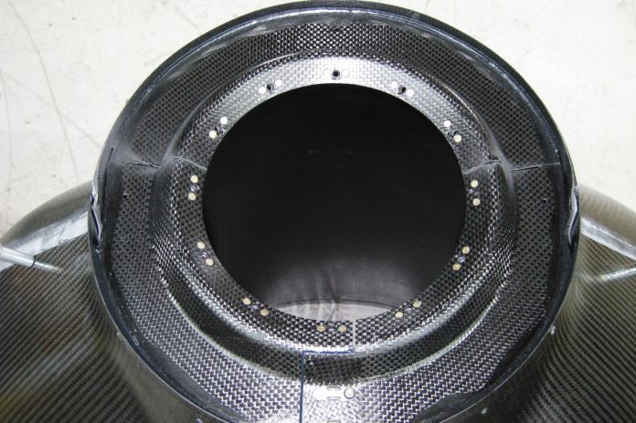
The ring bulkhead was bonded as a single piece to the assembled upper/lower left/lower right cowl parts to ensure circularity of the assembled parts. It was then split as shown here to allow the individual cowl pieces to separate from each other.
With the lower cowl now joined as a single unit, I was able to trim and fit it to the firewall joggle, upper cowl joggle, and 3d jig. I match drilled the lower cowl to the upper cowl and fuse, and added pad ups at the screw locations to allow for countersinking. (Note – pads ups can be avoided by simply adding extra reinforcement along the entire screw line during the initial layup. That is the faster approach for most builds, but in this case I did local pad ups to avoid the extra weight). Finally, a liquid shim (a paste of epoxy and microballoons) was added between the top/bottom and cowl/firewall joggle to ensure that all components sit flush with one another and that the fay surfaces perfectly match.
The final step for the main cowl was to construct a ring bulkhead that serves to maintain the shape of the forward cowl, and which also serves to support a seal that rides on the prop extension (the entire cowl is carefully sealed to avoid excrescence drag and force cooling air through the exhaust tunnel exit). This was fabricated on a 3d printed mold as a single piece, although it was ultimately cut into three pieces (for the top, bottom left, and bottom right cowl parts). The cowl was then assembled and all three cowl parts bonded to the ring mold. Once cured, the bulkhead was carefully cut to allow the three cowl pieces to split. Flanges and nutplates were subsequently bonded to the ring bulkhead to allow it to be fastened together when the cowl is assembled to the airplane. The bulkhead-to-prop extension gap seal was also fabricated and screwed into place.
At this point, the main cowl fabrication was finished except for some bodywork and heat shielding. The remaining items to be integrated were the cowl cheek extensions (they are permanently bonded to the fuse firewall aft, similar to the cheek extensions on an RV-4), the exhaust tunnel (also attached to the fuse firewall aft), and the heat exchanger inlet/outlet ducts. We’ll cover those in a subsequent article.
This article first appeared in the 2026 September Issue of KITPLANES magazine.