You spent countless hours assembling your homebuilt airplane, paying great attention to detail. No detail is too small to merit your attention because you want everything to be perfect. Your hard work and effort is a remarkable example of precision craftsmanship, and you’re pleased with the finished result and proudly show it off. The plane is a joy to fly, but as you do, you can’t help but notice a vibration. The signs are unmistakable: there’s a “rough” rpm range, the visors shake, the compass won’t settle, or maybe your feet get numb during a long cross-country.
At first, you may try to rationalize the existence of a vibration because, after all, piston engines do vibrate. But the surprising truth is this: Vibrations are most often the result of an imbalanced propeller assembly and not from combustion. Vibrations—even small ones—can damage engines, airframes and instruments.
Evidence of this comes from a 1973 study* commissioned by the Army Air Mobility Research and Development Laboratory. The study looked at the reliability and maintainability differences of two groups of helicopters with distinctly different vibration characteristics: One group was fitted with vibration-reducing rotor-mounted absorbers, the other wasn’t. In the study, the failure rate for the group fitted with the vibration absorbers was 48% lower and corrective maintenance was 38.5% lower.
Fortunately, diagnostic technology exists that allows homebuilt owners to easily identify and resolve vibration problems. The end result is a smoother, safer flying experience.
Looking for Trouble
The first step is to complete a baseline vibration survey to see what vibrations exist. Since vibrations aren’t always obvious, pilots and owners must learn to recognize symptoms such as these:
- Your arms, legs, or feet get numb during a cross-country.
- Your compass jiggles or won’t settle down.
- Instrument needles vibrate.
- Avionics randomly fail.
- There is an rpm range that is rough.
- You experience a “shiver” in your airplane as you reduce rpm prior to landing.
- Rivets loosen.
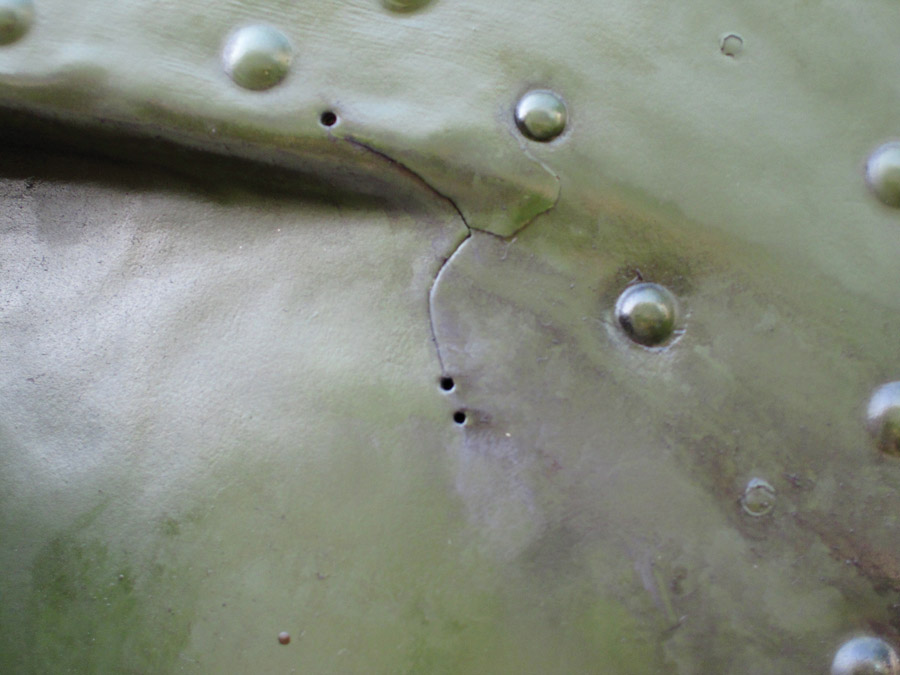
- Fatigue cracks appear or existing ones grow.
- Visors shake.
Surprisingly, many owners experience some of these vibration symptoms, but don’t link them to a vibration problem that is damaging their airplane. They’ve simply lived with the symptoms and assume they are normal, so the vibration doesn’t get their attention. It’s not uncommon for servicing, often prompted for reasons other than vibration resolution, to identify vibration as the root cause of a problem. When it is resolved, owners often feel as if they’re flying a new airplane and are amazed at how smooth flying becomes.
Other owners are more sensitive to vibrations, and when they become aware of one, they embark on a quest to find and vanquish it. When propeller assembly imbalance is the culprit, relief comes from dynamically balancing the prop, and most of the time, the prop is the cause of vibration. It’s pretty easy to detect and resolve prop imbalance with the proper diagnostic equipment.
If there is a “gotcha” where prop balancing is concerned, it is the belief that static balancing is all that is necessary. Statically balancing a prop is a great start, but a prop that is only balanced this way can still cause a vibration once it is mounted. The reason is simple: Statically balancing a prop doesn’t account for the entire rotating mass of the prop assembly. Once a statically balanced prop is mounted, dynamically balancing can detect an imbalance anywhere in the assembly and enable resolution.
Sometimes, owners dynamically balance their props and still a vibration problem persists. There are owners who have embarked on multi-year quests to troubleshoot a hard-to-diagnose vibration. You don’t have to do much searching online to find forum posts from owners pleading for ideas and help. Many have removed, cleaned, and synced carbs; rebuilt engine mounts; disassembled and re-shimmed gearboxes; or even all of these—and much more—to no avail.
The frustration of these owners is understandable. But they’re right to relentlessly pursue a solution because the effects of aircraft vibration are all negative. Vibration creates fatigue that reduces the life of the airframe, engine, and instruments. Furthermore, when a vibration exists, some of the energy meant for propulsion is directed toward shaking the airplane, and a vibration can even steal enough energy to cause a loss of horsepower. Identifying and resolving vibration not only results in a smoother, safer flying experience, it extends the life of the aircraft and enables peak performance.
Troubleshooting Complex Vibrations
When dynamic propeller balancing doesn’t resolve a vibration problem, spectral analysis is the approach that will pinpoint other vibration sources, such as: a weak cylinder, unbalanced carburetors, a loose or cracked intake hose, an alternator problem, belt resonance, gearbox issues, an oil-canning spinner, propwash, and other causes.
Spectral analysis, commonly referred to as a vibration survey or vibration analysis, measures the frequency of vibrations coming from an airplane. Vibration frequencies are associated with known causes or sources, so once the frequency is known, the list of potential causes narrows to few or one, eliminating the need for speculative and potentially expensive maintenance actions.
A case study of a kit aircraft manufacturer that contacted RPX Technologies, a vibration analyzer solution provider, illustrates how spectral analysis identifies complex vibration sources. In this particular situation, some of the engines this manufacturer was using were exhibiting vibration, and a significant amount of time and expense had already been spent searching for the source.
The symptom was engine roughness in the mid-rpm range that produced noticeable vibration. The vibration was diminished or unnoticeable at cruise rpm. A series of trial-and-error maintenance procedures were unsuccessful in resolving the vibration, and continued speculative service work was both costly and unproductive. The manufacturer was eager to pinpoint the vibration source and hoped that vibration analysis would identify what had so far been elusive.
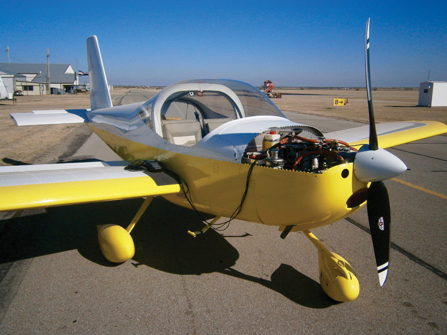
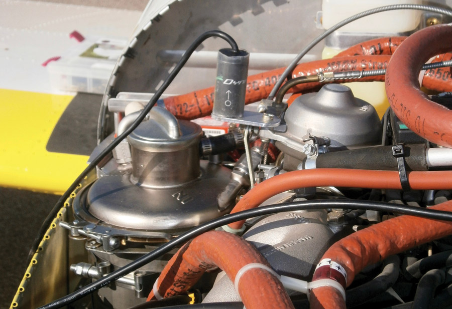
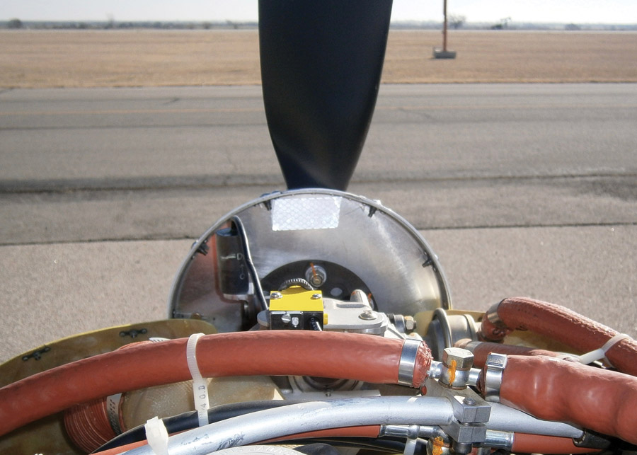
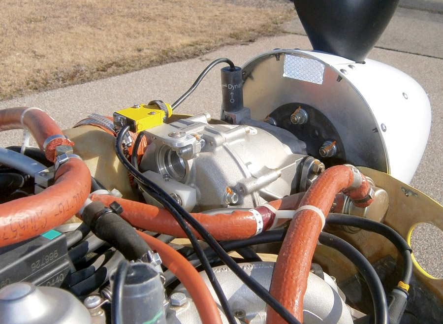
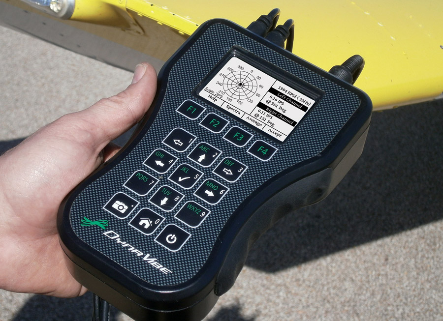
RPX Technologies visited the aircraft manufacturer that owned a DynaVibe GX2 vibration analyzer. The analysis process began by setting up the engine with a photo tachometer and two accelerometers. One accelerometer was mounted on the edge of the engine, and the second was mounted above the crankshaft near the front of the engine to measure propeller vibration. A single accelerometer is all that is necessary to dynamically balance a prop, but the second accelerometer enables recording different kinds of vibrations: prop and torsional. The photographs above show the stages of setting up a Rotax 912 engine for vibration analysis.
Once the engine was set up, a baseline vibration analysis was completed. This involved running the engine up to cruise rpm or the rpm range that exhibited the vibration symptoms, so the vibration analyzer could collect data. In the case of this aircraft, vibration data was collected at various rpm levels. When data collection was complete, after just a few seconds, the results revealed which vibrations existed.
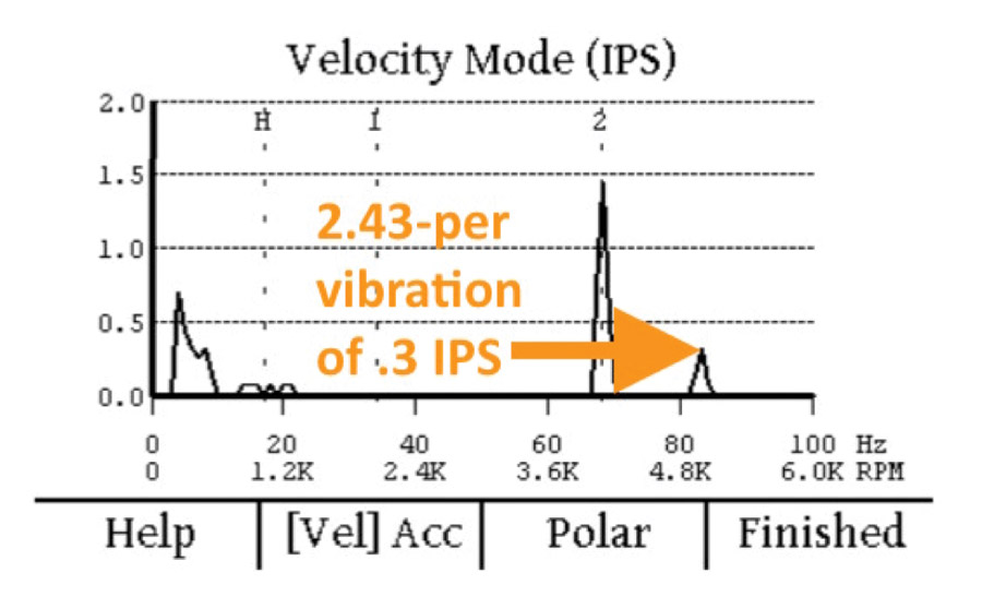
Those vibrations are visible on the velocity mode graph that the DynaVibe system generates (see Figure 1). The velocity mode graph displays the magnitude of the detected vibrations in Inches Per Second (IPS).
Each peak on the velocity mode graph represents a vibration; the taller the peak, the greater the vibration magnitude. The baseline reading was taken at an engine rpm of about 2500. Here, a 1.4 IPS peak is present at the 2-per-prop-rotation interval. A taller peak on the graph, slightly more than 2 IPS, indicates a vibration that occurs every 2.43 times per prop rotation.
Resolving the 2.43-Per Vibration
This engine exhibited a severe vibration at the 2.43-per interval, seen as the tallest peak on Figure 1, just to the right of the 2-per vibration. This vibration is due to a variation in the torque of the engine that occurs with every other cylinder firing, i.e., a strong cylinder fires, then a weak cylinder, then a strong, then a weak, etc. It is probably caused by the difference in intake lengths on the intake manifold of the Rotax 912 engine, with the front cylinder having a longer flow path than the back cylinder. This difference in front-back airflow causes a torsional vibration in the engine.
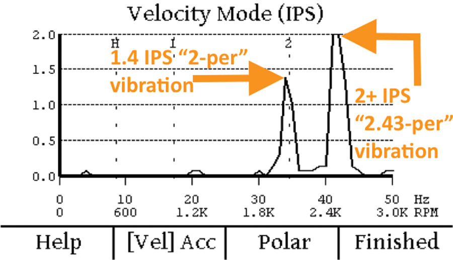
Figure 1: Results from the initial vibration analysis baseline runup reveal two significant vibrations.
A 2.43-per spike is typical for these engines, and it typically diminishes significantly as rpm is increased to standard cruise levels. If that is true, then the presence of a 2.43-per vibration on this engine is not a concern, but to confirm this theory, a second vibration survey was done at 5000 rpm. The results can be seen in Figure 2.
As expected, the 2.43-per vibration has almost disappeared at cruise rpm. For this reason, no remediation is recommended for this vibration. However, there is also a 2-per vibration that increases at cruise rpm.
Resolving the 2-Per Vibration
The 2-per vibration of this particular engine measured at 1.4 IPS is significant, and it gets worse at higher rpm. Ideally, an engine exhibits no vibration at all, but a vibration of .2 IPS or less is considered acceptable. In the case of this engine, the 1.4 IPS 2-per vibration, in combination with the 2+ IPS vibration from the 2.43 per was so strong that it was shaking gas out of the carburetor onto the exhaust manifold! In the mid-rpm range, the combined effect of the 2.43- and the 2-per vibration was very destructive and potentially quite dangerous.
The close proximity of these two peaks, one at 2-per (33 Hz) and one at 2.43-per (40 Hz) causes a beat frequency, similar in sound to a twin-engine airplane with the engines out of sync. Except in this case, the beat frequency was around 7 Hz, making the airplane feel as if the engine was running at 430 rpm—a very low rumble, exactly what the aircraft exhibited.
When the presence and frequency of a vibration is known, its source is narrowed to one or a short list of causes. How can one know what the various vibrations point to as a cause? When diagnosing machinery faults using vibration analysis, there are known industrial causes of vibrations based on their frequency. The prop on this aircraft was dynamically balanced prior to the baseline vibration survey, and the data confirmed that the prop was not the source of the vibration (a propeller assembly balance would have resulted in a 1-per vibration on the velocity mode chart). A 2-per vibration is related to something that rotates with the prop, and since the Rotax 912 is a geared engine, attention fell on the gearbox.
The cause of this 2-per vibration was confirmed by measuring the friction torque of the gearbox, which registered 66 foot-pounds, well over the manufacturer’s maximum of 44 foot-pounds and considerably out of spec. This vibration data provided certainty about the source of vibrations in the engine. The airplane manufacturer was able to work directly with the engine manufacturer to identify a permanent fix to the gearbox problem. No additional trial-and-error diagnosis was necessary.
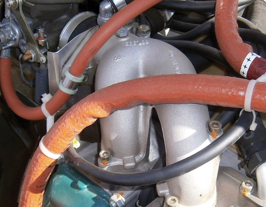
The differing flow-path lengths of the intake manifold can cause a torsional vibration in the engine.
This case study illustrates the value of vibration analysis in troubleshooting vibrations whose source is something other than the propeller assembly. Since the propeller accounts for vibration problems in a majority of cases, the vibration remediation process should always begin with dynamically balancing the prop. If that doesn’t resolve the vibration, the analysis will pinpoint the source: A half-per vibration indicates a combustion problem, a 1-per vibration is caused by prop assembly imbalance, and a 1.2-per vibration points to imbalanced carbs. Engine data provided by the manufacturer can help owners understand what these vibrations indicate, and the vendors of vibration analysis systems are also a great source of this information.
With the information provided by vibration analysis, an owner or mechanic doesn’t have to go on a wild-goose chase to find and resolve vibration problems. The value of vibration analysis goes well beyond just locating vibration sources; it is an excellent preventative maintenance approach. Performing regular vibration surveys enables early identification of maintenance issues while they’re still relatively small, before the vibration does much damage, or most importantly, before it results in failure.
*Vibration Effects on Helicopter Reliability and Maintenance, Angelo C. Veca, April 1973.
![]()
Matthew Dock is a registered professional mechanical engineer in Oklahoma. He is the co-founder of RPX Technologies, a provider of dynamic balancing and vibration analysis solutions for aviation and other industries. Matt is a licensed private pilot with over 1000 hours of time logged in Experimental aircraft. He owns a Long-EZ, Kitfox on floats, and a Cessna 172.

