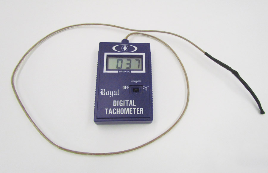
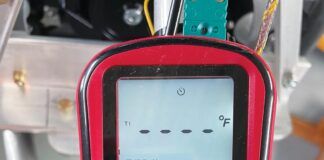
Ever want an inexpensive tachometer that can remotely sense rpm? I am in the process of building a rolling test stand to try out the CVT (variable drive ratio pulley as used in snowmobiles, etc.) that drives my prop and need to monitor both engine and propeller rpm. Like most projects, I’m trying not to raise the national debt buying parts for it. Having been involved in model airplanes for a long time, I had an optical tachometer on hand and decided to try moving the sensor to the end of a 3-foot extension. The first attempt was made with a Royal digital tachometer.
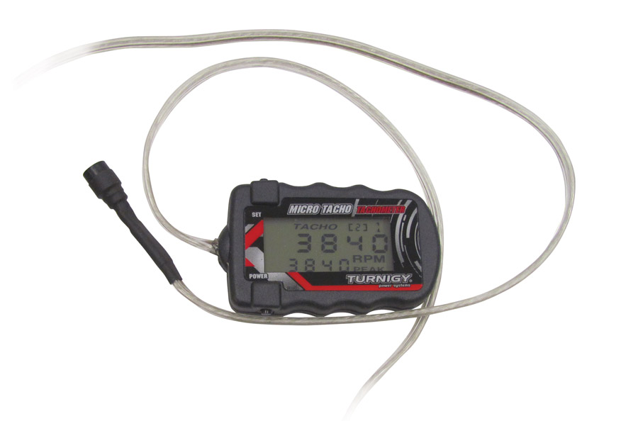
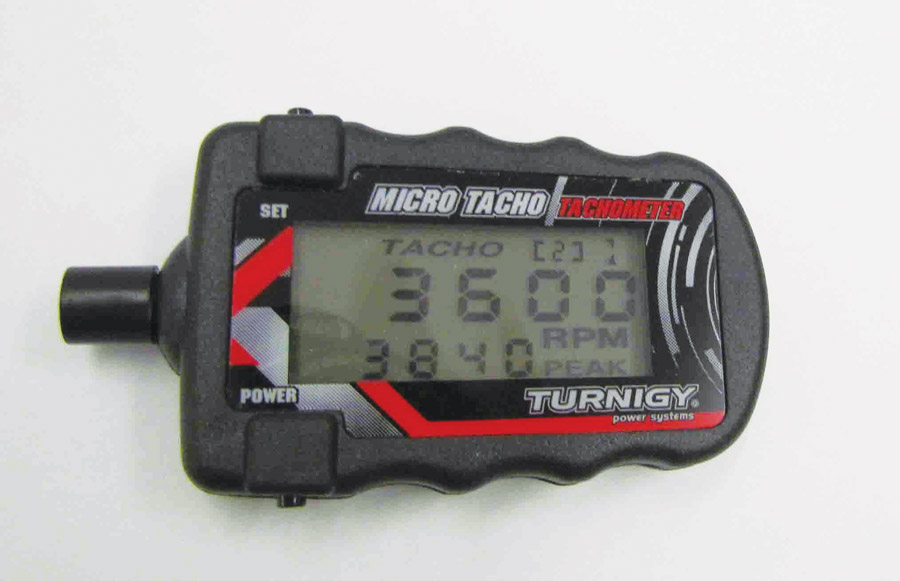
Although it worked fine, this was a 15-year-old three-digit tach, and I wanted something a bit more precise than the three-digit format. Three Turnigy tachs were ordered for a total cost of about $30. They are much smaller, display four digits, and will read anything between two- and nine-bladed props.
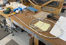
Here’s how to add the extension:

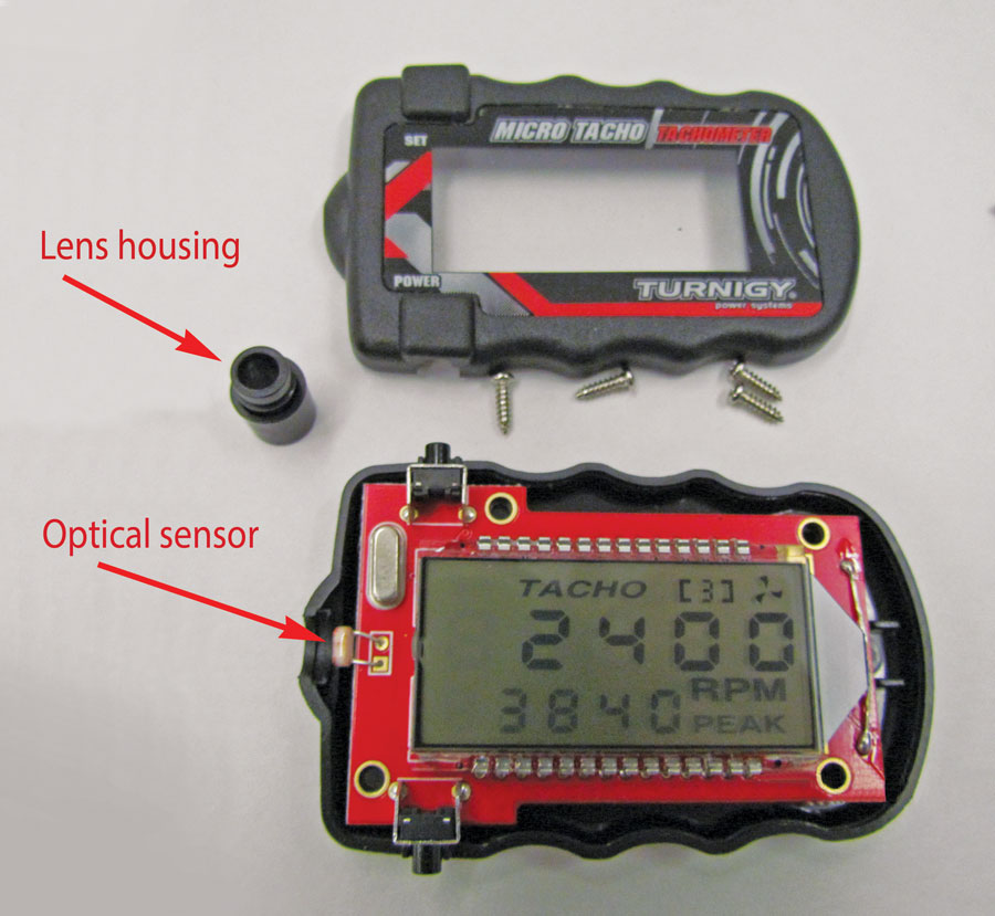
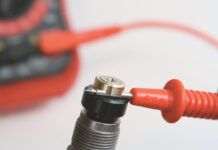
2. Cut the sensor wires and tin the ends of the extension. I have not experimented with the maximum extension length. Mine are about 3 feet long and seem to work fine.
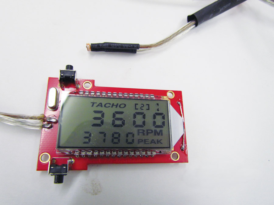
3. Solder the sensor to the extension and the extension to the printed circuit board where you cut off the sensor. Use the smallest soldering iron possible. Excess heat will fry the sensor. I know because I have one dead sensor. Clever of me to order three units. Use heat shrink tubing on the sensor wires.
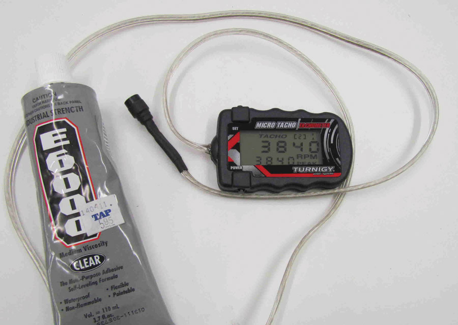
4. Attach the lens housing using heat shrink tubing and assemble the unit using a small dab of a vinyl adhesive like Amazing GOOP or E-6000 to stabilize the extension wire where it exits the tach housing.


I was searching the optical Tach to learn more about CVT’s as well. How did your test bench turn out, do you have videos on that?
Send me an email and I will pass along some data from the tests.
[email protected]
The CVT program was successful, but there was no follow-on program to apply it to an aircraft. I found the CVT allowed me to run a wide variety of prop sizes all the while keeping the engine rpm constant. I also found the CVT ratio changed with forward airspeed, which was the main question I had about such a system. Bottom line is that I am convinced a CVT would be advantageous over a standard PSRU, but don’t have any flight data to prove it. I do have reports, still photos and videos of the testing.
The rolling test stand has since been modified to test large diameter (11″ and 17″) ducted fans. The original 13 HP engine has been replaced with a 35 HP 2si engine.
The CVT system was removed when I swapped the engines. The unit I was using was good for about 12 HP and the 2si is about 30 hp. I would like to get back to the project and install the snowmobile CVT that I have obtained. It’s good for at least 60 HP.
The major problem I have had with the whole project is that I didn’t build it robust enough to withstand long term running. The vibration and torque forces are brutal and I now have a better understanding of the needs for such a system.
The ducted fans I have been testing were both built with salvaged jet turbine complressor blades from England and Russia. Unfortunately they aren’t optimized for this application and the thrust outputs are low as a result. To date i have gotten thrust numbers that are about 50% of what the theory says I should be getting. I did build in a ground adjustment for blade pitch so some data has resulted. Unfortunaetly, I am unable to attach the Excel files to this message.
I’d like to get a tachometer that can remotely sense rpm. Maybe I can try and build one too. But I’d like to see how a normal one works on its own.
I suspect all the tachs mentioned in the links run off an ignition lead of some sort. The objective of the one I made was to avoid any connections to the engine system. It does require routing a dual conductor lead from the front of the engine to the cockpit. The one I have installed had the sensor looking through the prop. The main difference is the cost and that my units would have to be consicdered a back up to a “real” tach in an expiremental aircraft.