Your aircraft’s engine requires monitoring of various temperatures for you to know that it will continue to purr along reliably for the entire flight. The engine systems usually monitored include oil, water, cylinder head (CHT) and exhaust gas (EGT) in order to make sure they fall within acceptable temperature limits. Falling outside of those limits is a reason for some immediate corrective action. We read these temperatures on a mechanical or electronic gauge—but how do temperatures get from the engine to the instrument panel?
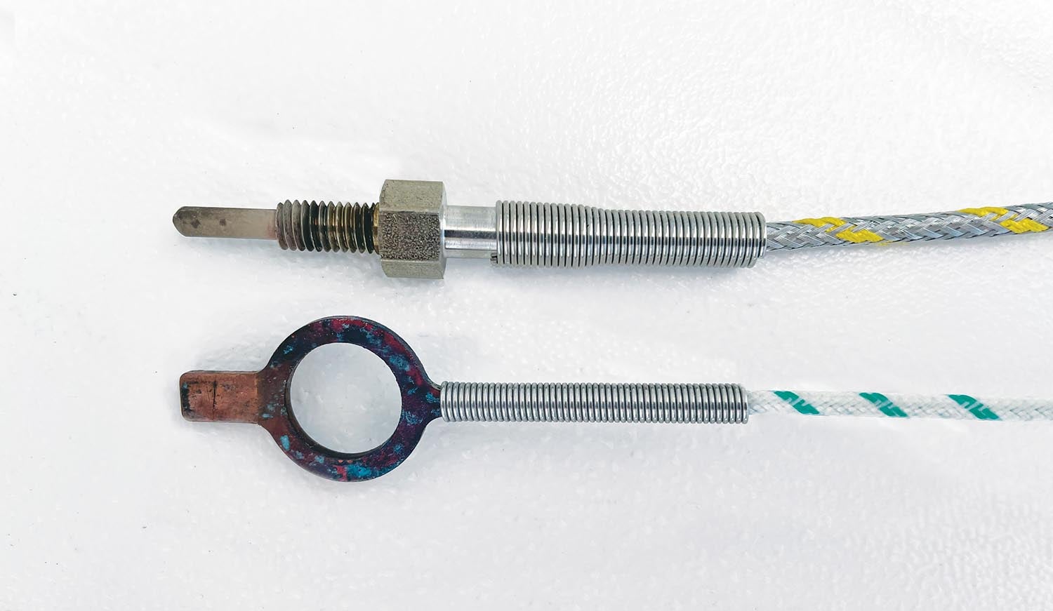
The most common method for taking temperatures is to use a wonderfully simple device called a thermocouple. Usually taking the shape of a probe (sometimes a ring), this small instrument is placed in contact with the material to be measured. It can accurately sense temperature in fluids (oil, water), solids (metal) and gases (exhaust). The thermocouple is an electrical device, creating a tiny voltage that rises with temperature. How does it work? What do we have to know about it when installing and wiring it up in our homebuilt?

The thermocouple is one of those amazingly simple devices that harness a wonder of Mother Nature. In 1821, a German physicist, Thomas Johann Seebeck, discovered that if you simply join two dissimilar metals together, a voltage is created at the joint, and the voltage rises with the temperature. That’s it! If you were to look inside one of your $50 thermocouple probes, you would find two wires bonded together. Nothing more. The magic of reading temperatures has to do with understanding the voltages created when using specific metals in those wires leading up to the joint. While many types of metals can be used for those two wires, the industry has standardized on specific metal alloys so that voltages and temperatures can be predicted for accurate temperature readings.
You may have heard of K type thermocouples (look at details when purchasing). This is a popular standard that uses two wires. One is made of a metal alloy called Chromel and the other of Alumel. Engineers have tested the voltages, which are generated to specific temperatures found at the junction of these metals. These values are recorded in charts so the circuit designer can calculate temperatures.
In order to determine the temperature at the wire junction (inside an EGT probe, for example), a thermocouple circuit is required. For a K type thermocouple, a length of Chromel wire is joined with a length of Alumel wire (this junction is hidden inside the probe). This junction is the “hot” end. At the other end of these wires (which can be any length and their temperature doesn’t matter) is where we take the voltage measurement. This is the “cold” end. If we know the temperature of the cold end as well as the voltage on the wires, we can use the K type engineering charts to determine the temperature of the hot junction. The principle can be generalized: If we know the temperature of either end (junction) and the voltage across the wires, we can determine the temperature of the other end.
What is important for us as builders to remember is that if the wires from our K type thermocouple are not long enough to reach the instrument panel, it is important to use the correct wire metal as an extension. If you use plain copper wire, you will have added a new dissimilar metal in a joint with both the Alumel and Chromel wire! This will alter the voltage and ruin the accuracy of the temperature reading. (The exception is if all joints always have the same temperature—which is rarely the case. Think: some joints near the engine exhaust pipes and others behind the instrument panel.) What we want to do is extend the Chromel wire with more Chromel wire—and the Alumel wire with more Alumel wire. This is what defines type K thermocouple wire. Amazon carries plenty of this wire; search for type K thermocouple wire. Solder your joints or twist them together. A bonus: The length and temperature of the wiring does not matter if you keep the wires a consistent material.
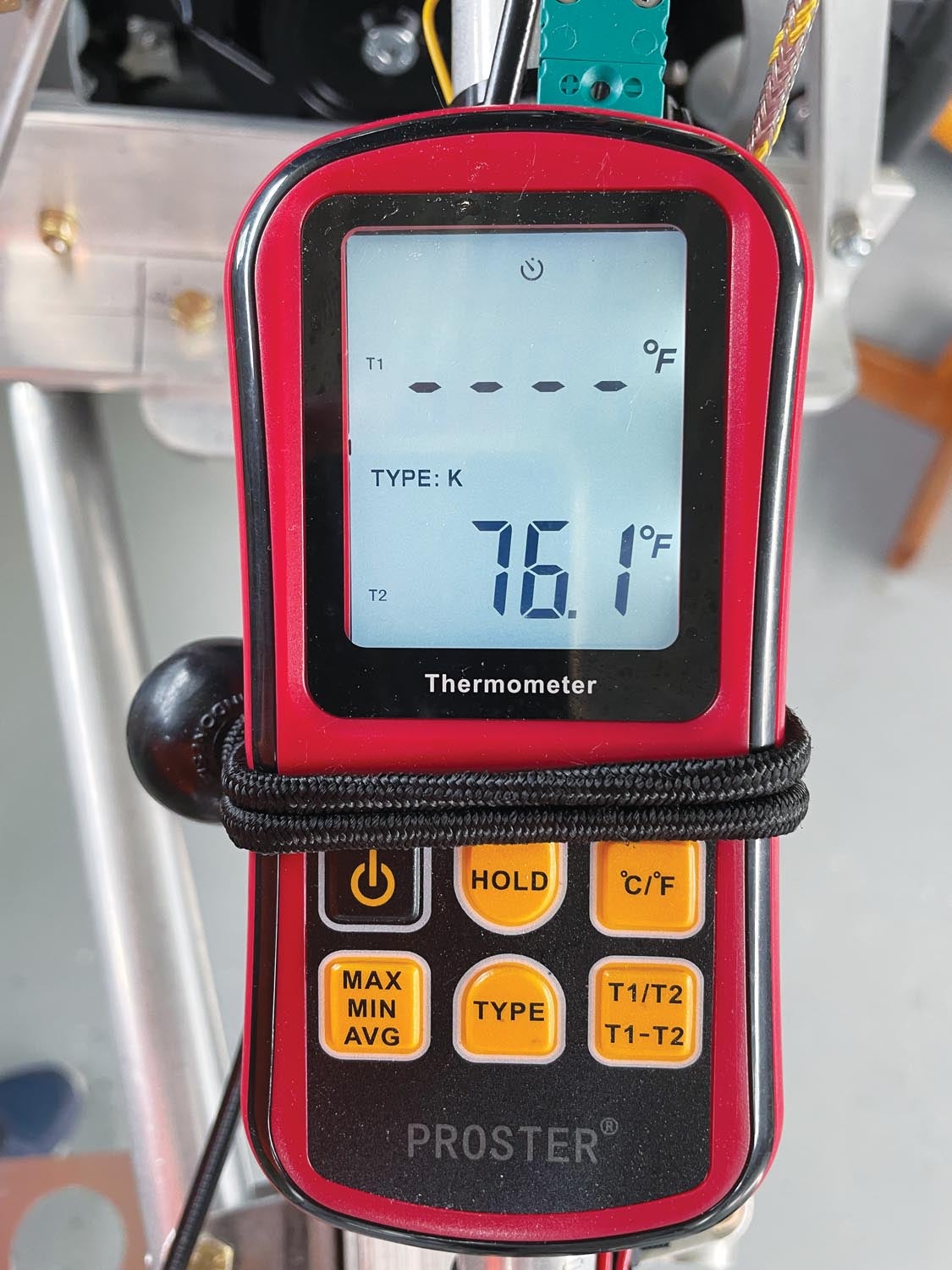
If you want to have some fun, you can play with (I mean test) your thermocouples before putting them into action on your engine. Inexpensive thermocouple meters are available from Amazon that provide a digital temperature readout of any thermocouple. This is a great way to test your installation or troubleshoot erroneous readings from your instrument panel. Set the meter to type K and look for an immediate reading. Put your probe in ice water or a boiling pot to check the accuracy from a predictable temperature source.
By understanding how those little thermocouple probes work, and how to design your wiring properly, you can rest assured that taking your engine’s temperature is easy, reliable and accurate. Plane and simple!
![[Credit: Radiant Technology]](https://www.kitplanes.com/wp-content/uploads/2026/04/550095_5165745cc27748a598699799d796fd94mv2.jpg?w=218&h=150&crop=1 "Radiant Technology Unveils SafeGyro")


