Way back in March ’23 (deep in snow here), I gave you the problem of Ernie, who needed a flashing light to see when something is being said on the radio. Finally, we’re going to finish the project by making a PC board for brother Ernie. I was hoping to get it done in time for him to make his trek to Oshkosh, but the PC board gods (demons?) declared otherwise. Between March and September, I started the “PC Board Series” and called upon Ernie to demonstrate the full usefulness of a homemade PC board.
I freely admit that as a college teacher, I would have given a student a C (out of pure generosity) if (s)he had turned in a board like this. Generally, the C would have followed the question, “What birdcage did you take this board out of?” In my defense, I point to the fact that my poor old above-the-garage electronics lab doesn’t have even one-tenth the resources (tools, equipment, chemicals, etc.) of a college workroom.
But let’s get on with it. As you may recall, we cobbled up an Ernie “breadboard,” so named because back in the 1920–1960 era, many a kitchen breadboard sprouted tubes and transformers despite the dire dirty looks given to we intrepid experimenters by either our mothers or our wives, depending on who was the kitchen warden at the time. Today, a piece-of-junk PC board sprouts haywire circuits intended to demonstrate proof of concept before committing a design to the expense of a commercial PC board manufacturer. But the title breadboard still clings to this circuit literally air-wired up and held in place by soldering ground connections to the copper PC board. Those were the images in the March ’23 issue.
Somehow Ernie and Murphy were shaking hands somewhere along the way. The first inkling I got was in August 2023, when a loyal reader attempted to make the first simple board. “Hey, Jim, I’m getting a lot of ‘pin-not-available’ errors trying to make this sample board.” Long story short, I put that program up on my website about four years ago, and on my own computer program I had updated some parts since then with pin connections you all didn’t get. It is now as up to date as the day I write this column, and I promise that if you download it again (Rev. B), you will get the right parts.
So, back in August I started writing this installment. Piece of cake. Just go back, review my college class notes and make a PC board.
What Happened?
Trial #1: Peeled the glossy photo image from the board after ironing the image on. Ninety percent of the printer toner stayed with the paper. I got a few wiggly lines and a pad or two. Something was wrong. I washed the board (acetone or xylene dissolves toner ink) and tried again. Same results. Seems like the toner wasn’t getting hot enough to melt onto the board. I put Cyndi’s iron back on the shelf and headed down to the “bull’s-eye” store (Target) for an industrial iron.
Trial #2: Fired up the iron on max temperature and tried again. This time about a third of the toner transferred. What the heck was going on?
Trial #3: A thought…the printer and toner were about 10 years old. I ordered a replacement toner cartridge, washed the old toner off the board and tried again. Two-thirds transferred.
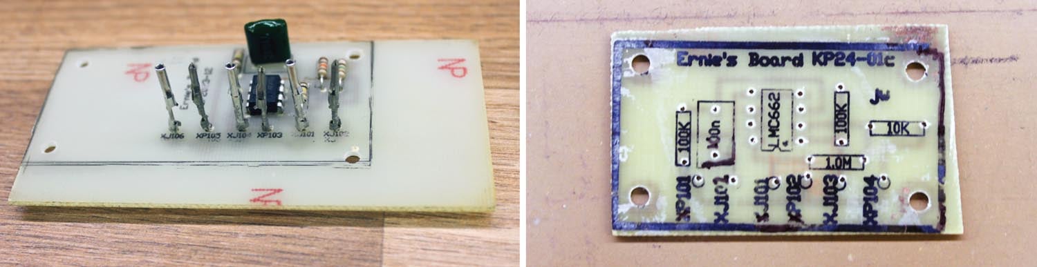
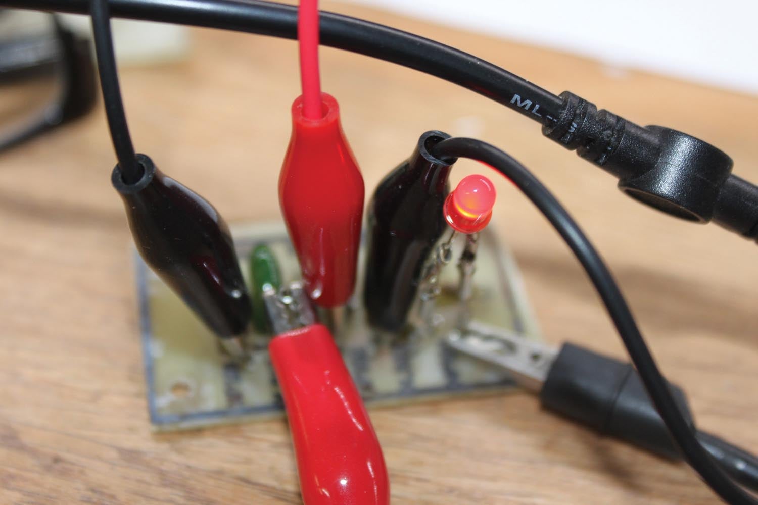
Trial #4: Another thought…the glossy photo paper was at least 15 years old, stored in an unsealed folder in a hot upstairs office. I ordered new paper and bingo! The result is the board you see in the images. All it took was a few bucks worth of parts, three weeks of messing around, plus two hours of work to make a good board.
So, here we are in the first week of September 2023 with the following recipe for the January/February ’24 issue:
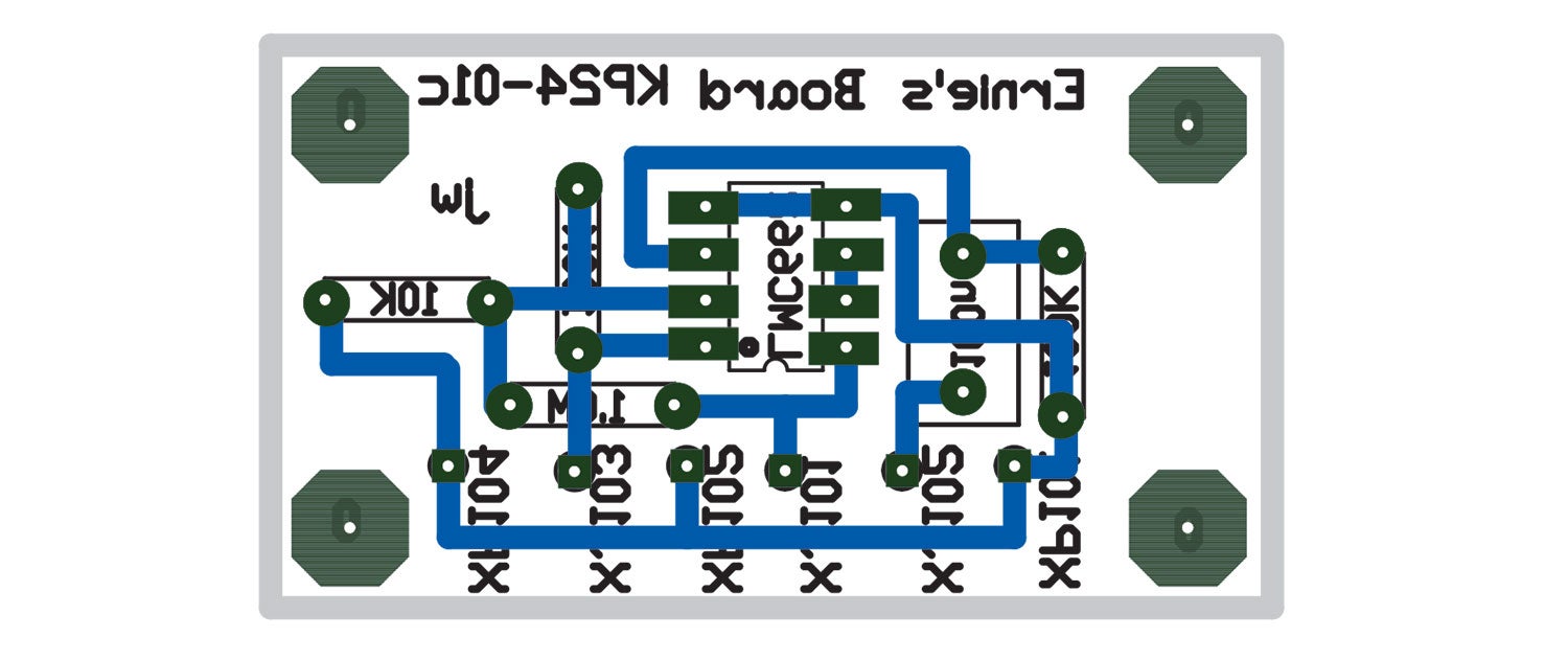
1. Lay out the PC board as described in the August ’23 issue. Print the board with a black-and-white laser printer onto fresh glossy photo paper, “regular” weight, using the print function of Traxmaker.
2. Cut the PCB image from the glossy photo paper, leaving a little bit (20 mils or so) of white edge around the image.
3. Cut a piece of PC board material the size of the board, leaving a small amount (50 mils or so) of excess outside the board edges.

4. Clean the PC board material as though you were going to eat from it. Scratch it using copper cleaner and finish cleaning it using cleaning powder and water. Do not touch the surface of the copper after this.
5. Using fingertips on the edges, put the board into a toaster oven on the lowest heat setting and dry the board for a half-hour of toasting.
6. Allow the board to slightly cool. Using fingertips, transfer the board to a flat surface (a scrap of aluminum sheet works well) with a heatproof underlayment (a scrap of plywood or tile works well).
7. Fire up the iron to the highest temperature. Place the glossy photo image (toner side down) on the warm PC board, on top of the aluminum, on top of the tile.
8. “Fix” the image onto the PC board with the iron on one corner of the board so that the image paper can’t move. Then iron the image onto the board. Iron it as though you were ironing a shirt. Keep the iron moving; the copper will act as a heat sink if you leave the iron in one place and the image will not transfer equally. Four minutes seems to be about the optimum between burning the paper and ironing the image.
9. Immediately transfer the image to a container of warm (not hot) water and allow it to gradually cool. You may see an image peeking through the back of the paper in about half an hour.
10. Peel the paper backing from the glossy photo paper slowly. Don’t try to do the whole thing at once. If one section of the paper seems stuck, don’t worry. Let it be.
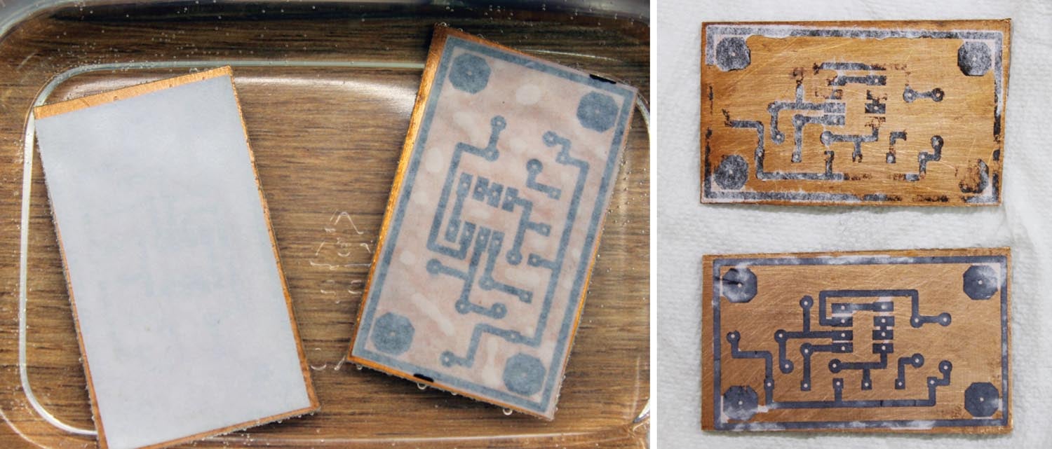
11. Muriatic acid from Home Depot comes as 26% hydrochloric acid meant for cleaning rocks and such from driveways and swimming pools. It is nothing to play with. Use rubber gloves. It also melts copper (and as a side benefit, paper) but not toner ink. Using a plastic container, put the board with any attached paper into a container and cover it with muriatic acid.
12. In a half-hour or so, you will start to see little islands of copper and the fiberglass board underlayment starting to appear. When the copper is all gone, remove the toner with acetone/xylene and solder your circuit together.
13. If you want to be eco-friendly, you can neutralize the leftover acid with Clorox. Add Clorox a thimbleful at a time until it stops hissing and bubbling. What you have left is saltwater and a roomful of chlorine gas that soon dissipates into the atmosphere.
14. If you want to put a “legend” (parts values and reference identifiers) on the top side of the board…
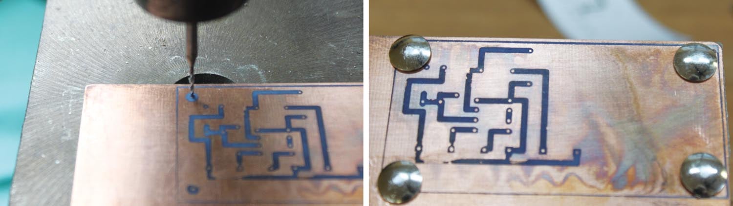
a. Before you start putting parts onto the board, drill two (or more) reference holes onto the board from the bottom.
b. Poke thumbtacks (PC board alignment pins) into these holes.
c. Print the “top overlay” (mirrored) onto glossy photo paper, find the corresponding holes in your alignment pins and put the top overlay on the board. Iron it on, as above: black overlay top, copper bottom, board done.
Now, not to negate all the fun you can have from acquiring a skill you can learn in no other way, you can go back to Step 1, produce “Gerbers” (see the CMTM program instructions) and send the board off to a custom PCB manufacturer. In a couple of weeks for $25 or so you’ll get a couple of professionally produced boards. I prefer www.oshpark.com as they are done in the U.S., but there are a dozen offshore (mostly China) folks that specialize in one-offs for about the same price.
Has this not been more fun than a person should have? How Cyndi put up with me coming in near midnight, cussing a blue streak, for the last month, I don’t know. But I’m happy she lets me rant about stuff that is supposed to work and doesn’t.
I may experiment with something I saw during the month from hell that I want to pursue for my own enjoyment. It seems as though I could use plain old copier paper instead of glossy photo paper with excellent results, but I could never reproduce them. I’ll let you know in a future article if I can find the secret. Back to cobble it together and make it play next month. Until then…stay tuned…


