Text and phonetically, yes. But if you will sit down, fasten your seat belt tight and just hold on, I will show you how to make a printed circuit board (PC board) for your Aero ’Lectrics projects using a laser printer, swimming pool with drugstore chemistry and scrap PC board material. The only tools you will need are the kitchen clothes iron and a good drill press with little tiny bits (preferably carbide). Ten bucks at the outside for stuff you probably don’t have, but you can use them in everything I design from here on out.
Over the years I’ve given you dozens of projects with “artwork” consisting of designs of schematics and PC board layouts that really looked nice in print, but would be nearly impossible for you to use to make your own project. I’m about to rectify that little problem.
Before you say, “Oh, I can’t do anything that complicated,” what I’m about to show you is what I taught in my community college classes to first-year students who couldn’t pronounce “curcut” much less design one. And I have never lost a student in 40 years and I’m not going to start now.
In the next three columns I’m going to take you from being able to make extremely simple PC boards through moderately complex ones, to finally making your own two-sided PC board for a magneto “buzz box.” From there on out, the most complex designs from my KITPLANES® columns are for you to play with as you see fit. If I do a strobe of some sort that you want to fit in a particular cavity on your airplane, you will soon have the tools to make the circuit board to fit that cavity.
But first things first. You need a program to draw your circuit and another program to convert that program into the lines, pads (“donuts”) and holes necessary to actually fabricate the board. You can find that program at my KITPLANES® page at www.rstengineering.com, then go to the lower left corner to “KITPLANES® Files” and then download CMTM2K.
It is vitally important that you read the “Read Me” files before trying to do anything remotely resembling a project. The problem is threefold. One, the program was designed back at the turn of the century and needs a fair amount of updating to bring it into modern times. Two, the original program did a lot of circuit simulation that never worked properly and needs to be trimmed of the excess before it is foolproof. Three, it needs to have a “parts bin” update to reflect parts that are selected (by me) to be the most common parts we will need for our projects.
One more caveat. This program was designed for Windows programs back in the day when 32k WinME was all the rage. It has been tested on Win10 64-bit machines and works well. Will it work on Win12? How about an Apple machine working under Windows simulation? I don’t know, and I don’t know. If any of you bit-bangers out there want me to post an alternate solution for other machines, I’ll be happy to do so, providing you send me the simple documentation to accompany the new program(s).
Let’s Get Started
OK, here we go with the kindergarten program that uses most of the simple commands that let us build a schematic that lights up an LED through a resistor from an external battery power source. And, of course, you have followed all the Read Me files and done all the updates that the Read Me files tell you about. OK, if the program doesn’t operate exactly as I tell you about in the next few lines, then stop and figure out what went wrong because if you try to do a “workaround,” you will be totally lost in the next two or three columns.
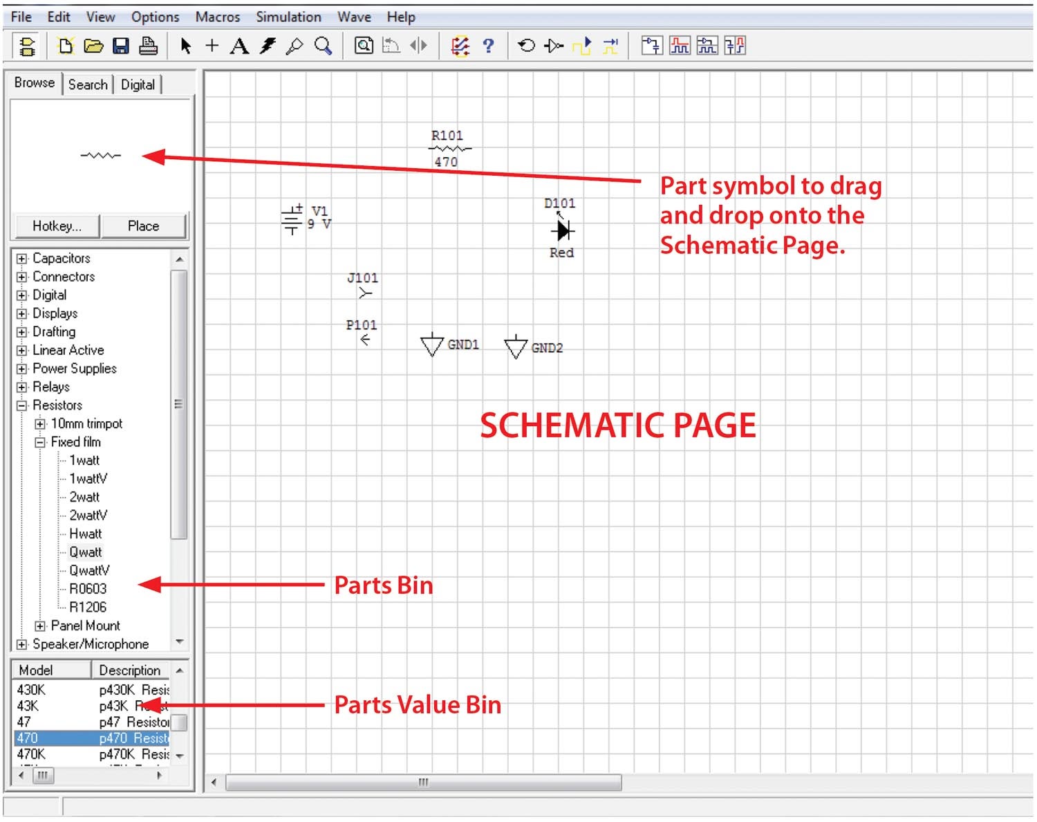
Somewhere in the CircuitMaker zip file that you downloaded, there will be a SetupCM2000.exe file. When you execute it, there will be cirmaker.exe and traxmaker.exe programs and an “Updates” folder. Follow the directions for the Updates files (especially the Models folder with all the updated parts necessary to construct our KITPLANES® projects). To be sure you’ve got this right, go to wherever your computer downloaded the cirmaker.exe file and open it. It will probably say “Text” on the center of the screen. Click on Text and delete it. In the far left menu “parts bin,” the choices should go from “Capacitors” to “User Defined” with 16 total choices.
If this isn’t true, then stop right now and figure out what went wrong…
OK, now that you’ve got it, we are going to make a simple circuit and a PC board to go along with it to simply light an LED from an external battery. Name this blank circuit with your-name.ckt.
On the left-hand parts bin menu, go to “Transistors and Diode.” Go to “Diode,” then go to “Lighted” (this gets you to the LED menu). Notice that now a submenu appears in the “Model” area. Pick your model of choice, noting that if you scroll down the menu for “Model,” you get your choice of colors and sizes. How about we pick a red one? Click one, but don’t double-click it. Now use the bottom arrow to show all the parameters of red LEDs that we have. Note that they are all the small T1 (3mm) size. That’s all I use. Note that I can have “diffused,” “clear” and “transparent” varieties of this LED. The next parameter is critical. This is the “pkg,” which is what CircuitMaker, the schematic and PC board design tool, is going to pass on to Traxmaker, the PC board layout program.
Notice while we were doing all this stuff that a schematic symbol appeared in the square of this column. If you want this as your choice for the PC board, simply single-click on it. Now double-click on it. You’ve got more of a chance to be sure that is what you want. You can change your mind (edit), throw it away (delete) or show the “properties” in a large format.
Note that the “Designation” is D1. And that D1 is visible on the schematic. Change D1 to D101. Here’s the deal: In my world, components from 1–99 are on the metal chassis. Components 101–199 are on the first PC board of the project, 201–300 are on the second PC board, and so on. Just my own personal preference.
Ah, but we need a current limiting resistor. Just out of the blue, let me suggest that a 470-ohm ¼-watt resistor might be appropriate. Fixed film might be nice. OMG—nine choices. Well, we said ¼-watt, so Qwatt might be appropriate, and if we want it to lie flat on the PC board, we don’t want the QwattV, which is standing up vertical on the board with one lead bent over vertical. Let’s see now, somewhere on the parts value list should be a 470-ohm resistor, and it puts that refinement on the board. And in the same way we should change the resistor to R101.
This next one is easy. Our power supply is a battery, but it will not go onto the PC board. However, we should show it on the schematic. Go to the parts bin and open up “Power Supplies.” Pull out a “Battery” and put the symbol onto the schematic. To save some time later, put a “Chassis Ground” onto the schematic. Select the Ground. Ctrl-C, Ctrl-V and make a duplicate on the schematic.
Just for completeness, select (double-click) the battery to look at all the things you can change in the “label-value” to your selected voltage source. Note at the bottom of the page there is a selection for “Exclude from PCB.” Check it. (A 9-volt battery is way too big for the PCB we are going to build.)
Two more parts and we are done. Somehow that external battery is going to have to be connected to the PC board. And we are going to connect it with a 2-cent connector (both pins). Go to “Connectors,” “Multi-pin,” “Single-pin F.” Put a single female pin on the board. Put a single male pin on the board. (X101 and X102.)
Done.
To be continued next month. Until then…stay tuned…


![[Credit: Zenith Aircraft Co.]](https://www.kitplanes.com/wp-content/uploads/2026/02/wksp-3-21-group1.jpg?w=324&h=160&crop=1 "Zenith Building Momentum With Workshops, New Options and Mosaic Opportunity")

I used to etch my own PCBs at home too, but in a world where you can upload your Gerber files to a PCB house in China, pay something like like $5 (no exaggeration) and receive high quality, factory-made PCBs in a couple weeks – faster if you’re willing to pay more than the $5! – I’m just not sure it’s worth etching your own PCBs anymore.
FWIW, for a modern and free schematic capture & PCB layout program, I’d suggest KiCad – it’s available for Windows, Mac, and Linux, and has no size or layer limitations that I’m aware of. No affiliation other than a happy user.
I totally understand what you’re saying. But as an engineer, I find it’s useful to still understand the process, and at least do it once or twice yourself before totally relying upon some fab shop. I’ve seen a lot of engineers fresh out of college who struggle because they were taught all the theory, but none of the practical application or hands-on skills that go with it. In my experience people understand something so much better once they’ve done it themselves. And sometimes simple circuits can still be done simply enough or crudely enough for quick prototyping and troubleshooting, before committing to a final design and having to wait for them to arrive to continue.
But there’s is nothing wrong with taking your approach.
I design PCBs for a living using Altium and Kicad. Great tools, but they are complicated and overkill for most people with steep learning curves. For hobbyist making fairly simple boards, EasyEDA is a great way to go. It is easy to learn and has been simplified to the bare minimum learning curve. It is linked to parts distributor LCSC and manufacturer JLCPCB. This makes it really easy to design your board and get it manufactured for extremely low cost. With expedited shipping you can have stuffed PCBs in a week.
Nothing wrong with etching boards (or CNC’ing them), but it can become a time consuming hobby all on it’s own. I still do it when I absolutely need a board by tomorrow, but most the time it doesn’t make sense.
Comments are closed.