KITPLANES Magazine, September 2002
Electric Powered Aircraft – Part 2
Selecting the right aircraft to electrify.
By Peter T Launie and James Dunn
This is the second article of a series on electric aircraft (the first appeared in the April 2002 KITPLANES). This series will trace the development of the world’s first fuel-cell-powered, piloted electric airplane, including the energy challenges, the component selection and other critical elements of the development project.
This project is focused primarily on developing a revolutionary new aircraft propulsion system that uses electricity instead of gasoline, so we decided to convert one of the most efficient existing airplanes to electric power instead of designing an original airframe. History Previous attempts at electric aircraft have primarily involved gliders, motorgliders or unpiloted aircraft with enormous aspect ratio wings. These aircraft tend to be designed for soaring and/or lengthy times aloft and use basic electric power for self-launching. The ultimate objective of Aviation Tomorrow, however, is to provide GA with a safer, more reliable and environmentally friendly alternative to the traditional internal-combustion (IC) aircraft engine. The smaller plane presents its own host of design problems, however, not the least of which is managing the heat from the electrical components, weight and balance of the small airframe, and simply fitting all of the necessary components in such a small space. Crusie Range Let’s review a little Aerodynamics 101. Optimum cruise for an aircraft is defined as the velocity that requires the minimum amount of fuel, or in our case, energy to fly a given distance. There is a certain velocity for every plane that takes the least amount of energy per mile to move the plane through the air. This does not occur at the minimum speed or the velocity for minimum power. Useful load is another important factor to consider when selecting an aircraft. Aerospace engineers usually use weight fractions, or what percent of the total weight of the plane is devoted to something. When talking about an aircraft’s design, they will mention terms such as fuel-weight fraction or empty-weight fraction. This puts planes of all sizes on a level playing field mathematically. Airframe Scoring The next step was to look for a high-performance two-place aircraft that upon inspection appeared to have the characteristics that would meet our objectives for electric flight. This would be a litmus test to see if there were any existing aircraft suitable for conversion. To begin this comparison, we took the most common GA aircraft on the market, the Cessna 172, and scored it as a baseline for comparison to the rest of the candidates. A quick Internet search yielded the specifications for the Cessna: It’s useful to note here that other more subjective factors come into play when selecting the right airframe, such as cost and availability, space for batteries, and compatibility with the GA market. When we were doing our initial evaluations, the 2000 Oshkosh AirVenture show was quickly approaching, and what better place to scout aircraft? We also operate on a limited budget, so any deal we could cut with a manufacturer would weigh heavily in the final decision. We looked at several aircraft at AirVenture, emphasizing those manufacturers that expressed interest in the project.
One of the more important aspects of converting an aircraft to electric propulsion is selecting the proper airframe to convert, and this is not an easy task. First, one has to decide what aspects of the aircraft are most beneficial to the goals of the project. Then one must determine their relationships to each other and, finally, the projected operating performance. Aviation Tomorrow spent several months defining a set of parameters that identify exactly what to look for in an airframe and then meticulously reviewed kit and general aviation (GA) aircraft to find the right plane.
Previous electric and solar-powered aircraft are not representative of the mainstream GA market. According to a recent study by NASA, the typical GA plane is a four-place, single-engine aircraft with flight characteristics much like the Cessna 172.
We chose to look at two- and four-place planes that had the ability to cruise at a respectable pace and with traditional wingspans and payloads. Motorgliders have the range to compete with GA aircraft, but they lack many features and are less suitable for passengers and other GA needs.
Aviation Tomorrow’s initial goal was to be able to fly at least 100 miles nonstop – solely on electric power. That’s a short distance, but the lessons learned would be invaluable. We also set other arbitrary objectives: a takeoff roll of less than 1000 feet, minimum climb rate of 750 fpm, fixed tricycle gear, and a stall speed of less than 45 knots. These requirements dictated that weight, performance and range would be the driving factors in selecting the target plane for conversion.
To begin with, Aviation Tomorrow looked at the aspects of GA aircraft that affect cruising range. Although a four-place aircraft might be preferable to accommodate the objective of augmenting GA requirements, we chose to initially convert a two-place aircraft for two reasons:
When using an internal-combustion engine, its poor efficiency at relatively low power settings must be accounted for, so manufacturers tend to publish cruise speeds that are a little higher than they could be.
Actually, according to Dan Raymer (author of AIAA Aircraft Design: A Conceptual Approach), the speed for minimum power and minimum drag can be expressed as: (See Fig. 1 and Fig. 2.)
It turns out that the velocity for minimum power is about 76% that of minimum drag. At that speed, the plane is using 13.9% more power, but because the speed when flying at minimum drag is much greater than when flying at the speed for minimum power, it takes only about 86% of the total energy to fly a given distance.
For those who are a little rusty on aircraft design, French aviation pioneer Louis C. Breguet’s range equation has been used for many years to estimate the range of an aircraft. It can be shown through using a little calculus that the range of an aircraft is: (See Fig. 3.)
where V is the velocity, C is the specific fuel consumption, L/D is the lift-to-drag ratio, and Wi and Wf are the weight of the aircraft at the beginning and end of the flight, respectively.
This does not really work for electric aircraft because Wi/Wf = 1 for electric planes, and ln(1) = 0. But the meaning of it still holds true. If we have two different aircraft of the same weight, with the same engines burning the same amount of fuel and flying at the same speed, the one with the greatest lift-to-drag will fly the farthest. Thus, the best lift-to-drag ratio was one of the driving factors in selecting our aircraft.
In the first phase of the project, we are building the plane to fly solely on batteries. We call the amount of batteries the plane can hold the battery-weight fraction. Obviously, the larger the fraction of batteries, the longer the range could be. Because every plane is different, and there is no way of knowing exactly how many batteries or how big a fuel cell each plane could carry, we looked at the empty-weight fraction of each plane. In fact, we set up a relationship to show the approximation that the battery-weight fraction = 1.0 – the empty-weight fraction.
Preliminary calculations on a popular high efficiency, two-place aircraft, the Europa, built by Europa Aircraft, indicated that with state-of-the-art battery technology achieving nearly 200 W-hr/kg, flights of 80 miles (140 km) might be possible. These calculations used basic physics and mechanics concepts and did not include a detailed analysis of flight mechanics. Modeling of the actual aircraft would be much more in depth and include a detailed analysis of the flight characteristics, a detailed study of electric motor and propeller performance, and their interaction with the installed energy storage system.
Assuming the published data for economy cruise of the Europa, 51.58 m/s at 3000 meters is the point in the flight envelope that the airframe is experiencing minimum drag for the given takeoff weight. Given the fuel consumption rate of 10 liters per hour (7.2 kg/hr) at that velocity, much data could be extrapolated about the flight characteristics of the aircraft. The Rotax 912 engine fuel consumption is approximately 0.350 kg/kW-hr. Therefore, at cruise, the engine output is approximately 7.2kg/hr/0.350kg/kW-hr = 21 kW.
Assuming no change in propeller efficiency, to duplicate the performance of the installed IC engine, an electric motor with an output of at least 21 kW would be needed to cruise. This motor should have a 200-300% overpower potential for short periods, providing about 63 kW (84 hp) for takeoff. To keep the estimate conservative, a propeller efficiency of 0.70 is assumed, with the plane in level flight (not accelerating), and the thrust equal to drag at 51.58 m/s.
Thus, the drag experienced by the airframe (factoring in a 30% loss through the propeller) is 0.70 (21,000W/51.58 m/s) = 284 N (Newtons). A lower efficiency propeller would actually decrease the calculated drag on the airframe. However, to be conservative, a higher efficiency propeller is used in these calculations.
Given that the empty mass of the aircraft is 358.2 kg, removing the mass of the installed engine (73.75 kg) leaves the total mass of the empty airframe at 284.5 kg. Maximum gross takeoff mass is 635 kg. All other masses remaining constant, this leaves an unused mass of 350 kg, allowing for 135 kg of batteries, a 45-kg electric motor and controller, and two 85-kg pilots. Using advanced LiIon batteries with an optimum specific energy of 200 W-hr/kg, a total energy of 27,000 W-hr (or 9.72×10⁴ kJ) could hypothetically be stored on board.
Assuming that the new electric motor and controller have a combined operating efficiency of at least 0.80 and are run at 300% for 2 minutes during takeoff and climb to a low cruising altitude, and factoring the energy loss through the motor and controller, a total of (63kWx120s)/0.80 = 9450 kJ, or 2625 W-hr is required.
There are at least two issues here to deal with. Overpowering the motor for 2 minutes may not be feasible without magnet damage, and a larger motor may be needed. Also, delivering enough peak current to sustain 63 kW may be a problem for the batteries, which were selected to provide highest specific energy (versus specific power).
The installation of thin metal film batteries or ultra capacitors to boost the current for short amounts of time may be necessary. To give a 10-minute reserve before landing, (21 kWx600s)/0.8=15750 kJ (or 4375 W-hr) are required. This leaves 72,000 kJ (20,000 W-hr) for the cruise, assuming that the batteries can be fully discharged, which should not usually be done.
The weight of the aircraft remains constant during flight, so the power required during cruise will also remain constant. Time aloft is therefore determined by energy remaining divided by the power output, multiplied by the combined motor and controller efficiency of 0.80, (0.8×72,000kJ)/21kW = 2742s, which at 51.58 m/s yields a maximum theoretical range of 141 km if all the energy was used. This is not recommended, but it’s used as a maximum gauge of potential performance.
However, this does not include factors such as climb to a specified altitude, power to run the avionics, any maneuvering during flight and reserve for climbing out of a missed approach, which will all limit range. Nor does it take into account any benefits that might be gained in optimization of the load of batteries, the airframe, the mission specifics or the augmentation of energy storage with power generation aloft (such as using a fuel cell).
Hopefully, the proper optimization of the airframe, integrated propulsion system and battery storage, and the addition of an efficient power-generation source on the aircraft will stretch the range to achieve the initial goal of 100 miles or 160 km.
Obviously, this procedure is oversimplified, but at the same time it’s too involved to be applied to every available aircraft. To narrow the two-place GA and kit aircraft conversion candidates, and do it fairly, required objective criteria. Math is about as objective as it gets. The aerospace industry often uses what are known as non-dimensional quantities when describing special characteristics. Non-dimensional simply means that there are no units such as length, mass or velocity associated with it. We decided to create a non-dimensional score to rate the planes that would take into account the two items we determined to be critical: the lift-to-drag ratio and the empty-weight fraction. (See Aircraft Scores.)Cessna 172 (Skyhawk) Specifications Empty weigh (no engine) 1275 lbs. Max gross weight 2450 lbs. Best glide ratio (Maximum L/D) .9:1 VSO 57 mph VNE 123 mph Score 4.3
Our target candidate list included the Diamond DA20 and H-36 motorglider, the Europa, the Pulsar and the American Ghiles Aircraft (AGA) Lafayette or MCR-01 kit. Meeting with the respective manufacturers, Diamond and AGA expressed interest in our project. After two days of discussions, both said they would be willing to donate an aircraft. The price was right, but would the aircraft meet our overall requirements?Europa XS Specifications Empty weigh (no engine) 626 lbs. Max gross weight 1370 lbs. Best glide ratio (Maximum L/D) 17.1:1 VSO 51 mph VNE 200 mph Score 9.29
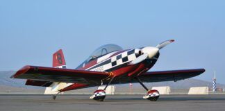
After considerable analysis, we decided that the AGA MCR-ULA (Lafayette 3) aircraft would be the easiest to convert, although we are also working on plans for the Diamond H-36, which was donated by Diamond Aviation of Austria. The AGA Lafayette is a bush version of the MCR-01, with slightly longer wings at 28.5 feet.
Final Selection
The Lafayette 3 score came to almost twice the Cessna’s and a little more than 15% better than the Europa. The size is also right. Although it’s only a two-seat airplane, it affords plenty of room in the cockpit and in firewall-forward volume. The plane climbs at more than 2000 fpm on an 80-hp Rotax 912. It also has a virtually all-composite fuselage, both skin and bulkhead, which might help greatly in preventing unwanted shorts of the electrical system.
| ||||||||||||||
Although any of the candidates might be good conversion choices, the manufacturer of the Lafayette agreed to custom-build our plane with special compartments in the wings and without gas tanks, making this less of a conversion and more of a clean-sheet design. AGA delivered the airplane to Oshkosh in July 2001, and it’s currently being converted to electric propulsion.
The next article in the series will focus on selecting the propulsion system including the electric motor, controller and propeller.
James Dunn is president of Advanced Technology Products, Inc. and vice president of CTC/FASTec. He is currently involved in the development of a piloted electric aircraft. For more information, contact him at CTC, 1400 Computer Dr., Westborough, MA 01581; e-mail [email protected]. Track the fuel-cell project on the web at http://www.aviationtomorrow.com/.
Peter T. Launie is an aerospace engineer at NASA’s Center for Technology Commercialization. He is also the engineering program manager for Aviation Tomorrow and is responsible for overseeing and planning the component and systems integration of the airframe, and performance analysis and modeling of the electric airplane and its subsystems. Send e-mail to [email protected].

