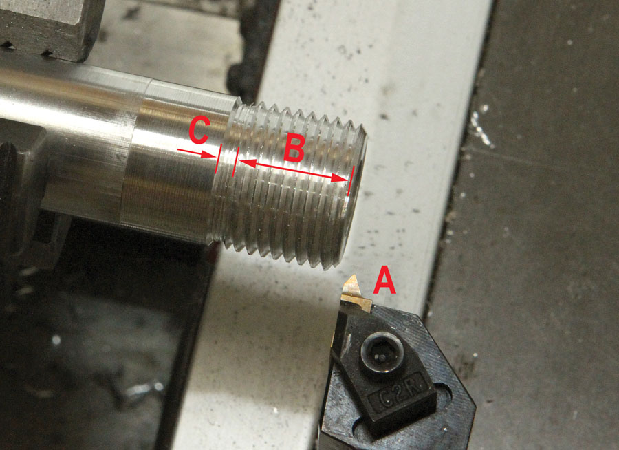
Chasing a thread (B) on the lathe involves engaging the feed system to make several passes using the 60-degree thread-form tool (A) until the thread is cut to the final depth. The relief groove (C) is a space for the tool to “land” when you disengage the feed after each cutting pass.
Thread chasing is a term used to describe the process of making a screw thread on a lathe. Strictly speaking, any lathe can be used to chase a thread. But in the context of metalworking, the term is predominantly associated with making threads in multiple passes, using a single-point tool, on a lathe having a gear-driven tool feed.
Although most lathe work does not involve threading, I would never consider owning a lathe without the capability to make threads. With some exceptions (such as turret lathes or micro benchtop machines), virtually all metal lathes, including so-called “engine” lathes and “toolroom” lathes, have the capability to cut threads. Any lathe that advertises a gearbox or change gears (or both) can make threads.
A complete how-to on thread making would take up a year’s worth of KITPLANES. The best I can do in one column is touch on the basics and, hopefully, demystify the process. Making threads on the lathe is sort of like crosswind landings—you need to read and study the subject at length to prepare, but you never fully get it until you go out and do it.
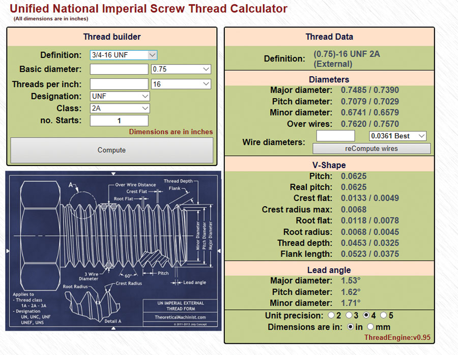
Every thread-making job starts with the dimensions specified by the Unified Thread Standard (UTS). For the sample part for this column, I googled “3/4-inch x 16 thread specs” and scores of reference sites popped up. One very nifty site was TheoreticalMachinist.com, which provides an app that lets you select a thread from a dropdown menu and fills the entire page with everything you need to know to make or inspect a thread.
Using an app at TheoreticalMachinist.com detailed specs for any thread are only a few keystrokes away. (Screen capture courtesy of TheoreticalMachinist.com)
To cut a standard screw thread, you need a 60-degree thread-form tool. Since it would be impractical to own a special tool for every different pitch, threading tools are made so one tool can be used to make a range of threads, say, for example, 16 to 32 threads per inch (TPI). Although I prefer to use insert tooling (see “Cool Tools for Lathe Work,” KITPLANES August 2015), you may find it more economical to practice with lower-cost, high-speed steel (HSS) tools. Little Machine Shop offers several thread-form tool options, including pre-ground HSS tools. You can also grind your own, but that’s a subject by itself and too in depth to go into here.
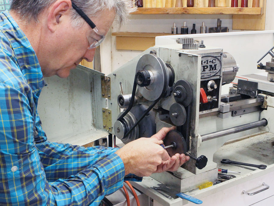
Swapping the gears in the headstock of my home-shop lathe. The spindle drives an idler gear, which turns a series of reduction gears, which turn the lead screw.
Machine Setup
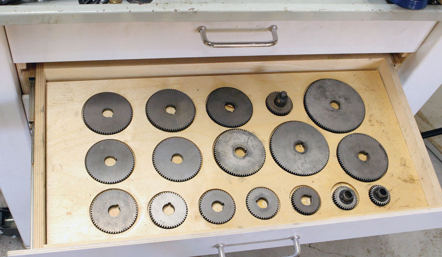
Industrial lathes have gearboxes that allow you to select any thread by moving a few levers. Many benchtop lathes also have gear-switching levers, but you often also have to swap out one or more of the change gears to achieve a particular pitch. Then there are the small, home-shop and hobbyist lathes where every pitch change requires swapping out the change gears. While somewhat of an inconvenience, swapping gears is not complicated. But it is the reason home shop lathes are lighter, more compact, and thousands of dollars less expensive than a lathe with a gearbox.
The change gears that came with my lathe. I built the stand to include this drawer to keep them organized.
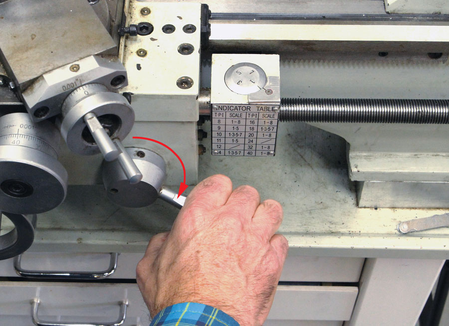
Regardless of the type lathe you have (gearbox or change gears), it will have a way to engage the lead screw to advance the tool carriage. This is usually in the form of a lever connected to a “half nut” on the right side of the carriage. A thread dial will also be incorporated into the carriage. The half nut lever is used in conjunction with the thread dial to sync the cutting tool to the thread pitch. Adjacent to the thread dial (or, if not, look in the owner’s manual) will be a chart that tells you what numbers on the thread dial to use with a particular TPI. Working the half nut lever in conjunction with the thread dial is the trickiest part of chasing threads on a lathe. It takes some practice, but you will get it. I promise!
When the half nut is not engaged, the thread dial spins around. As the correct number lines up with the “engage” mark, you lever the half nut closed. You have to make this move with conviction, as in one dynamic motion, to assure the lead screw syncs with the correct notch on the thread dial. Any hesitation or half-hearted attempt usually results in missing the mark. If you miss the mark and feed the tool into the part, it will be out of sync and wreck the thread! To account for this possibility, start with the carriage an inch or more away from the part. That way, if you miss the sync mark, you can quickly disengage the half nut before the tool makes contact, move the carriage back, and try again.
Every lathe has a thread selector guide to show the gearing, or gear selector position, required for a particular thread. The 16 TPI example is circled.
The half nut lever is rotated (red arrow) to engage the lead screw with the Number-1 mark on the thread dial. Note the thread dial with the 1-3-5-7 indications and the chart for synchronizing the carriage movement.
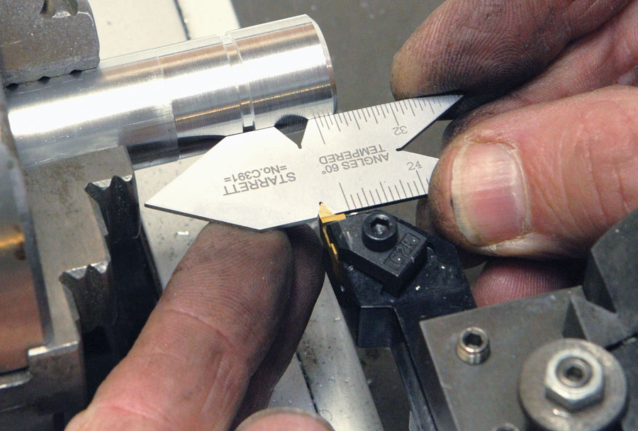
The final steps before threading are setting the tool and preparing the material. First, set the compound slide to 29.5 degrees (for parts of the lathe, see “Machines,” KITPLANES November 2013). By setting the compound to this angle, it presents the thread-form tool, which has a 60-degree V shape, into the part at an angle. Compared to plunging the tool perpendicular to the thread, this reduces the cutting forces and makes for a cleaner thread. Second, set the tool post so the tool point is on the centerline of the part and perpendicular to the work axis. Third, with the lathe set to a “normal” spindle rpm, use the thread tool (or if you have a quick-change tool post, a suitable turning tool) and carefully turn down the area you want to thread to the diameter specified by the UTS numbers. The example of -inch x 16 TPI needs an OD between 0.7485 and 0.739 inch. A good set of digital calipers will do because the tolerance is fairly generous (a micrometer is necessary for later, when you inspect the threads). Step four is to decide the thread length and turn a relief. For this example I chose 5/8 inch for the thread length and then made a relief groove to the thread depth (see next paragraph) using the thread-form tool. This relief groove is characteristic of most custom-turned threads. It provides space for the cutting tool to dwell when you disengage the feed screw after each cutting pass (see opening photo, detail “C”). The width of the relief can be arbitrary, keeping in mind that the coarser the pitch, the faster the tool will traverse the part. A wider relief provides a greater margin of error for “landing” in the relief area.
A “fishtail” thread gauge comes in handy for setting the tool perpendicular to the work axis. It’s also useful for checking the angle on hand-ground thread tools.
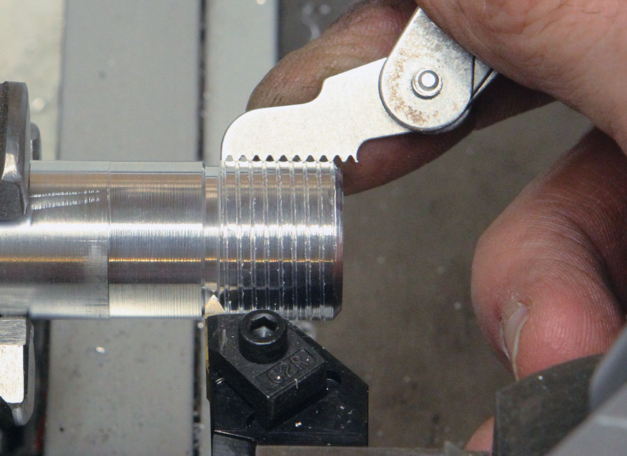
Checking the first shallow “scratch” pass with a thread pitch gauge to verify the gears are set correctly. Note where the tool stopped in the relief groove.
Almost Ready to Cut Threads
You are now ready to cut threads. Wait! Not so fast! One last step! With the machine off, bring the point of the tool up to the part and “zero” both the cross-slide dial and the compound-slide dial. The amount to remove in the threading operation is the thread depth. For 3/4-inch x 16 TPI, that number is 0.037 inch (the difference between the major diameter 0.748 and minor diameter 0.674 divided by 2).
Remember, we’re cutting the threads by advancing the compound, so we must factor in the 29.5 degree angle. To do that, multiply the desired thread depth by 1.15 to get the amount to advance the compound for the thread depth. In this case it’s 0.04255, but it’s OK to round it up to 0.043.
Now you are ready to cut threads! Without touching your zero-set dials on the compound or cross slide, manually move the carriage to the right of the part at least one or two inches. Advance the compound to 0.005 inches depth of cut, and with the lathe set to the lowest possible spindle rpm, turn on the lathe. Since 16 TPI allows you to engage the half nut on any whole number 1 to 8 on the thread dial, you can do that, or to keep it simple, use Number 1 every time until you get the hang of it. When you engage the half nut, the carriage will traverse, and the cutter will make a very shallow thread cut. Disengage the half nut the instant the cutter exits the thread area into the relief groove. Turn off the lathe and check the work with a thread-pitch gauge.
For subsequent passes, retract the tool using the cross slide, not the compound slide. I back out the cross slide one full turn, which on my lathe is 0.100 inch. This is needed for the tool to clear the part when you move the carriage back to the starting point. Again, do not retract the compound slide. Leave it at the depth of cut after each pass. With the carriage repositioned, return the cross slide back to zero. This puts the tool back where it was when you made the previous cut. Advance the compound another 0.005 to 0.010 inch. Turn on the lathe and engage the half nut (again, use Number 1, if that makes it easier to remember). And so on!
Repeat the “thread chasing” procedure, feeding in ever-smaller increments to keep the cutting forces in check as you get closer to the final depth. While the best way to inspect a thread is with the “three-wire method” of measuring the pitch diameter (we’ll save that for another day), for practice work and non-critical parts, it’s fine to have a compatible nut to check the thread.
So, why not cut the thread in one pass and be done with it? Thread making removes substantial material. Trying to hog it all off in one pass is not possible. To get a clean and useable thread, you have to take a series of relatively light passes.
Practice engaging the half nut with the machine on, but without a tool or part in the lathe. Do it as many times as you feel necessary to get the feel for “nailing” the thread dial pointer and disengaging the nut to arrest the feed. For your first try, use an easy-to-machine material such as aluminum or Delrin plastic.
If all this seems like a lot, remember that you probably felt the same way the first time you sat behind the stick in a cockpit. Yes, it takes practice. But after a few tries, it’ll all come together and make sense. In fact, it’ll be easy! And, finally, I have prepared a companion video to go along with this article:










It’s good to know that thread making can remove substantial materials. A ton of people might assume that cutting it is easier. But you need to take your time sometimes.