
We have come a long way with light emitting diodes. They went from $200 a bulb in 1968 to 5 cents a bulb in 1972. I personally went from a nerd slide-rule engineer in the ’60s to the revolutionary HP-35 LED digital calculator in ’72. That was painful. At $400 a copy, it was half the monthly salary of a junior engineer but worth every penny. Instead of half an hour of laborious hand calculations (in which there was always an error of some sort), it was less than a minute of furious button pushing, but it almost always guaranteed a correct answer.
It has taken a while for the aviation industry to adapt to LED technology. Perhaps the first one was a rather unsophisticated red LED instrument panel floodlight to replace incandescent bulbs in the company Cessna 182A instrument panel overhead floodlight (KITPLANES®, September 2003 by an author that had brown hair back then). Sixteen itty-bitty little popcorn-kernel-sized bulbs. Today, nearly 20 years later without a failure, that same floodlight uses the same 16 itty-bitty…
Through the years, KITPLANES® has run numerous articles on using LEDs for position (nav) lights, anti-collision beacon lights and some variations on the instrument panel lights. This may well be the last chapter in the death of incandescent lights for aircraft use. Today we begin to tackle the landing/taxi light problem.
The problem is this: Incandescent lights are intended to get hot. Indeed, the term incandescent implies that the source of the light is a wire that is heated to the point of giving off visible light. The more the light, the hotter the wire. Here the challenge is finding a wire that won’t become molten and disintegrate at these temperatures and how to keep the metal wire from oxidizing and fracturing. First, Swan in England showed how to make a wire glow, then Edison figured out how to keep it from burning out sometime in the late 1890s.
Heat does not make an LED glow. Electrons jumping from one energy level to another makes the LED glow. An unfortunate byproduct of this jumping is the production of heat in the body of the LED itself. The LED being about the size of a grain of sand, it doesn’t take a lot of heat to cause it to chemically decompose, which causes it to stop being a light source. It is a microscopic dance between getting a lot of light and turning the LED into a tiny little brick.
For some years now, we’ve been struggling with some rather expensive materials to make bright LEDs with some way of getting rid of the heat. Recently (in the last two or three years) we’ve come up with a way of mounting the LED on a thin layer of insulator over a thick layer of aluminum—the so-called metal-backed PC board. That brought the multi-watt LED from $50 a pop to a buck and a half a copy.
When I did the nav light and anti-collision light articles for KITPLANES® a decade ago, 1- and 2-watt LEDs were still going for $10 apiece, and today 3-watt LEDs are down to $1.50 a copy. That makes it feasible to do a 30-watt landing/taxi light for less than $30 each.
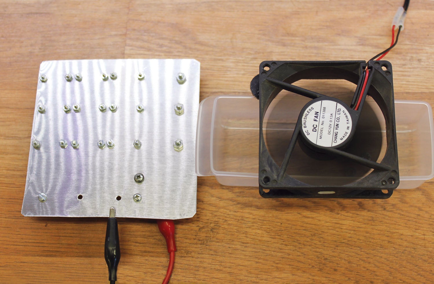
But we still have problems to overcome. Thirty watts is still a whole bunch of heat to get rid of in a fairly small area. And, since LEDs are not voltage driven, but current driven, we need to take our voltage supply and turn it into a current source. Both of these problems are solvable, but it takes some effort and compromises to make this transformation happen. (You’ve probably heard the old saying that “All aircraft are a collection of compromises flying in a loose formation.”)
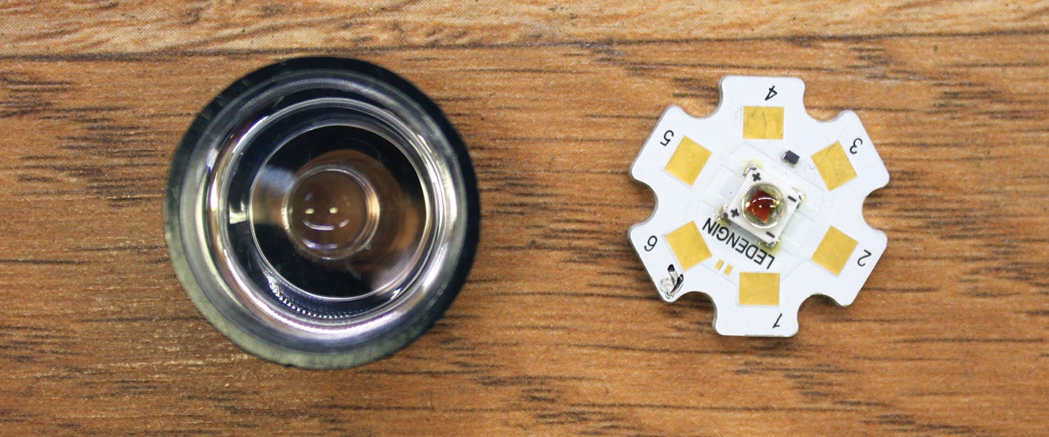
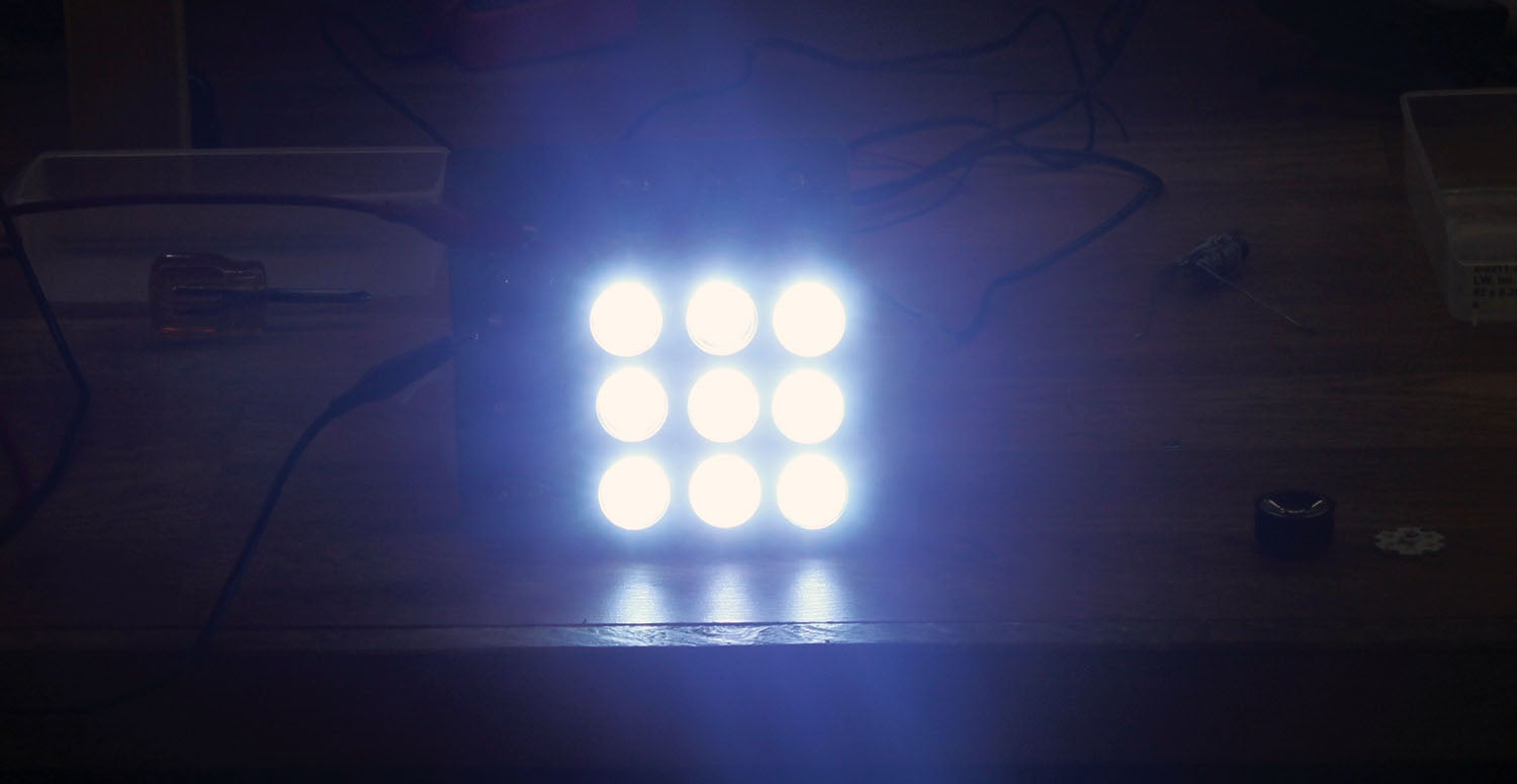
There is a company, All Electronics that is breaking the cost barrier for 3-watt LEDs (Part Number LED-248 and LNS-58) at about $1.50 each. For “daylight” LEDs we’d like the LED color temperature to be down in the area of sunlight, 4000K or so. For “pure white” (and therefore very bright), we’d like them up in the 6000K region. And, to get 30 watts we are going to have to use 10 of the bulbs.
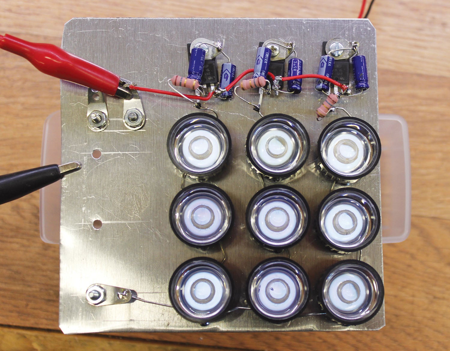
Now we get down to compromises: The LEDs will have a dropping voltage of about 3.3 volts each, which means we need to run three of them in series in order for any electronic regulator to have some “headroom” from a 12-volt supply. Instead of 30 watts, this means that three strings of three 3-watt lamps each will be used, or a drop from a 30-watt device to a 27-watt device.
Second compromise: LEDs emit their light over a wide angle. There are some expensive ways of beam-forming the LED chip itself to take all the light and narrow the beam to a spotlight, but the less expensive way of doing it is to take a cheap plastic lens and narrow the beam down to focus it in the direction we are traveling. The lens is as expensive as the LED itself, so we find ourselves in the realm of $3 apiece for the LED/lens combination. Now we are up in the $27 range for the whole light.
Third compromise: Three strings of lights means three current sources. And since our battery/alternator supply is going to be giving us somewhere between 13.2 and 14.4 volts, we might consider using a single resistor to be our current source. Let’s see what that does for us. The LEDs want 700 mA to operate. So as not to overcurrent them, we’ll take the high voltage (14.4) from the battery and the specification of 9.6 volts for three of the LEDs in series, which means we need a resistor of (14.4 – 9.6) / 0.7 ohms = 6.8 ohms at (0.72 * 6.8) = 3.3 watts. The next higher standard power rating is 5 watts, which is a fairly hefty resistor. We’ll need three of them for all three strings.
Third compromise compromised: Without going through all of the math in the last paragraph, the low output of our battery supply, 13.2 volts, means that we are not going to have the rated current through our LEDs, and we are not going to get the full brightness we want.
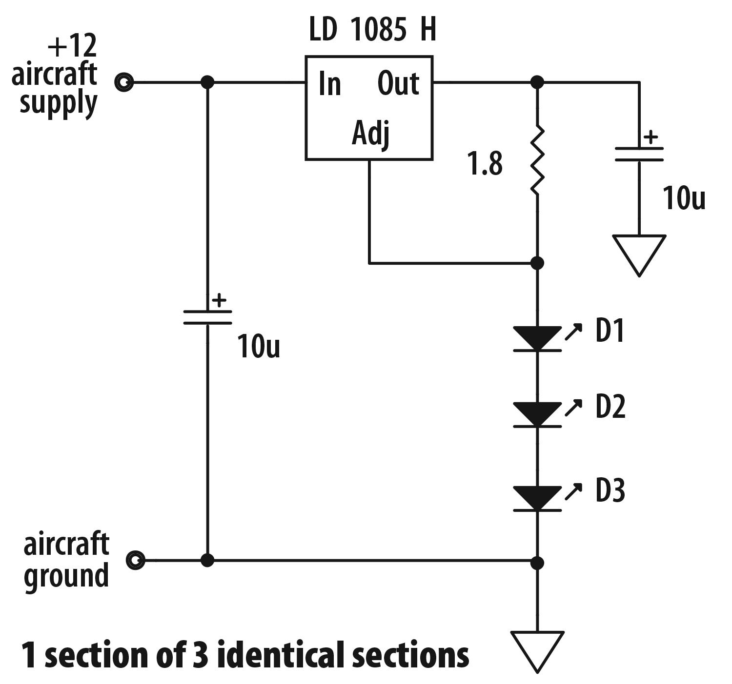
One way of solving this problem is to convert a voltage regulator into a current regulator. This is a fairly simple thing to do with an integrated circuit regulator and a single resistor. Using a regulator chip in a plastic package means that we can bolt the regulator directly to a metal chassis without using a separate insulator, fiber shoulder washer, and all that folderol.
This design is what we in engineering call a “proof of concept” project. The question at the beginning is not the optimum design, but it proves that the design can actually be done. Now the problem resolves itself to doing the project cheaper, smaller, easier to make and brighter. In a few months we will do that, but for now…stay tuned.
Photos: Jim and Cyndi Weir.


![[Credit: Lisa Turner]](https://www.kitplanes.com/wp-content/uploads/2026/02/Fuel-Selector.jpg?w=324&h=160&crop=1 "Fuel Follies")


Jim, I am confused! You used a 2.6 ohm resistor at the RF1 position. How did you generate that value. thanks.
Now I’m confused. I don’t have a CLUE what RF1 is, and I said IF I was going to use a resistor it would be 6.8 ohms. I went on further to say if I converted a voltage regulator into a current regulator I could do it with the voltage regulator and a current sensing resistor of 1.8 ohms. I have no idea what 2.6 ohms is or where it came from.
The 1.8 ohm resistor that I used with the voltage regulator comes from the regulator’s internal reference voltage (1.25 volts) divided by the current required (700 mA or 0.7 amps). 1.25/0.7 = 1.78 ohms. The closest standard value to 1.78 is 1.8 ohms.
Thanks for reading. jw
Jim, agree with your answer, thanks! My confusion is with your picture with the nine LEDs. It looks like the color code of the resistors is red-blue-gold….which I read as 2.6 ohms. Clearly I am confused! Your help is appreciated. Thanks again.
Jim take a look at our website our new XeTREME LED par – 36 Landing and Taxi versions.
320,000+ continuous output 10,800 lumens, 100 watts, 1 LUX at 1/3 mile 1/2 LUX at 1/2 mile
http://www.xevision.com
3 watt LED’s are low power 5,/6 watt LED’ are medium power, we use hight power Cree LED’s at 13 watts and only 7 of them for a 4.5 inch diameter Par-36 lamp. Must use very large optics as we do to columate the light into a far reaching landing light (it’s a matter of physics). Small optics and many low or medium output LED’s are only suitable for a good taxiing light,. http://www.XeVision.com
3 watt LED’s are low power 5/6 watt LED’s are medium power, we use hight power Cree LED’s at 13 watts each and only 7 of them for a 4.5 inch diameter Par-36 lamp. Must use very large optics as we do, to columate the light into a far reaching landing light (it’s a matter of physics). Small optics and many low or medium output LED’s are only suitable for a good taxiing light,. http://www.XeVision.com
Comments are closed.