 “Holy Cow!” I exclaimed, flapping my arms like a crazed gazelle, “This is amazing!”
My wife stood to one side, giving me a sideways glance and casting about for the lost marble that must surely be rolling across the hangar floor.
The reason for the excitement and disjointed chicken dance was shadow puppets cast on the trees up the taxiway, across the runway, down the next taxiway and into our neighbor’s yard at the airpark (around 300 feet away). These were caused by my gyrations in front of one wing tip and were a stark contrast to what was a barely discernible glow with the old 75-watt halogen bulbs previously installed.
This all came about as a result of sagging voltage on a recent night flight while getting in the required three takeoffs and landings to a full stop. I don’t usually fly at night, but changing circumstances meant that it was going to be happening more often, and the dropping voltage was a bit of a worry. Although the alternator was rated at 60 amps, it uses a slightly oversize pulley (to reduce rpm at the alternator and prolong bearing life), so at low or idle rpm, it is probably producing only a small fraction of its rated capacity. Not a big deal at cruise, but a bit of a problem with multiple stop ’n goes.
Tallying up the total amperage draw of the incandescent position lights, traditional strobe lights and 75-watt halogen lights (times two) gave a whopping 24.5-amp draw with everything lit. However, I had heard about a kit produced in Australia by a company called Flyleds. And according to their website, everything could be swapped out to LEDs, and it would drop the total amps down to only 10.
Armed with optimism, an order to Australia was placed and about a month later (it being Christmas and all), “The Works” kit arrived at the front door, complete with tail position/strobe LED.
Some Assembly Required
Flyleds is not your typical supplier of ready-to-install lights. Their standard kit includes circuit boards and lots of components, carefully packaged in well-labeled and organized bags. The kit is very comprehensive, including mounting hardware and even the appropriate solder to get you started. If you want to pay a little extra, they can do all the soldering for you, but where’s the fun in that? Besides, my wife says the only thing cheap in aviation is pilots!
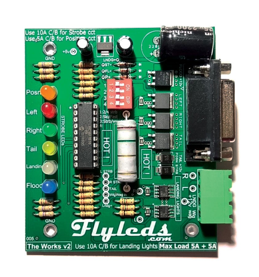
This was a little intimidating. I had done almost no soldering on circuit boards before. However, armed with a new temperature-controlled soldering iron (a new project is a great excuse to buy tools), I set to work and within a short amount of time, a completed controller board sat on the bench.
The controller board does a number of things: It regulates the juice flowing to each of the various LEDs and keeps them in their happy range. It flashes the strobe LEDs on and off and controls the wigwag function for the landing lights. It manages the output to the taillight, keeping it at a low output all the time when the position lights are on and flashing to a high output for the strobe function. The board also facilitates a special “flood” feature that uses the strobe lights running at 1/3 normal power to provide a floodlight feature around the airplane, which is helpful for taxiing. The flood feature can’t be used when the strobes are running and vice versa, but this really isn’t a problem, as you wouldn’t want to blind other aircraft by running the strobe lights on the ground, anyway. The bottom line is that pretty much everything connects to the controller board, so it’s a good idea to install it in a fairly central location. One exception to this rule is that if the controller isn’t needed to direct the wigwag function of the landing lights, it can be bypassed. This can be helpful if the airplane already has a wigwag module, or if wigwag isn’t desired, as it means you can reuse existing wiring.
The controller board is designed to fit inside a standard plastic project box. I purchased the box separately but ultimately decided not to use it, as provision needs to be made for connecting a 15-pin D-sub to the controller board, along with up to four wires for the landing light connections (main feed, left wing, right wing and wigwag switch), and the box seemed like more trouble than it was worth. Included with the kit is a handy, 3-D printed mounting base that the board clips into and which facilitates attaching to the airframe with four mounting screws. In my case, I used some plastic (UHMW) standoffs to keep the board completely clear of metal structure and to make it easy to connect the D-sub and other wires.
Less Current, More Light
One of the handy things about LEDs is that they use less current and therefore work well with smaller wires. For my installation, the original strobe control box made a nice, central location to install the new controller board, and the 4-conductor strobe wires already at that location provided a great way to feed the new LEDs. In the case of the position lights, the old incandescent position light in the tail was fed by a 22-gauge wire running right past the old strobe box, so this was repurposed to provide switched position light power to the new controller board. Although it originally served only a single incandescent position light, the 22-gauge wire is sufficiently large to feed all three of the new LED position lights through the controller board. Only two of the wires within the old strobe cables were needed for the new strobes, so the remaining two were repurposed to carry the position light current out to each of the existing light locations on the wingtips. This covered both the position and strobe light wiring, and in my case I was re-using the existing landing lights wires and switches, so the only new wire to be installed in the airframe was the one from the switch panel to the controller for the floodlight feature. Of course, whether running one wire or many, this still meant pulling up all the floorboards to fish the new wire through the conduit.
Building the Wingtip Boards
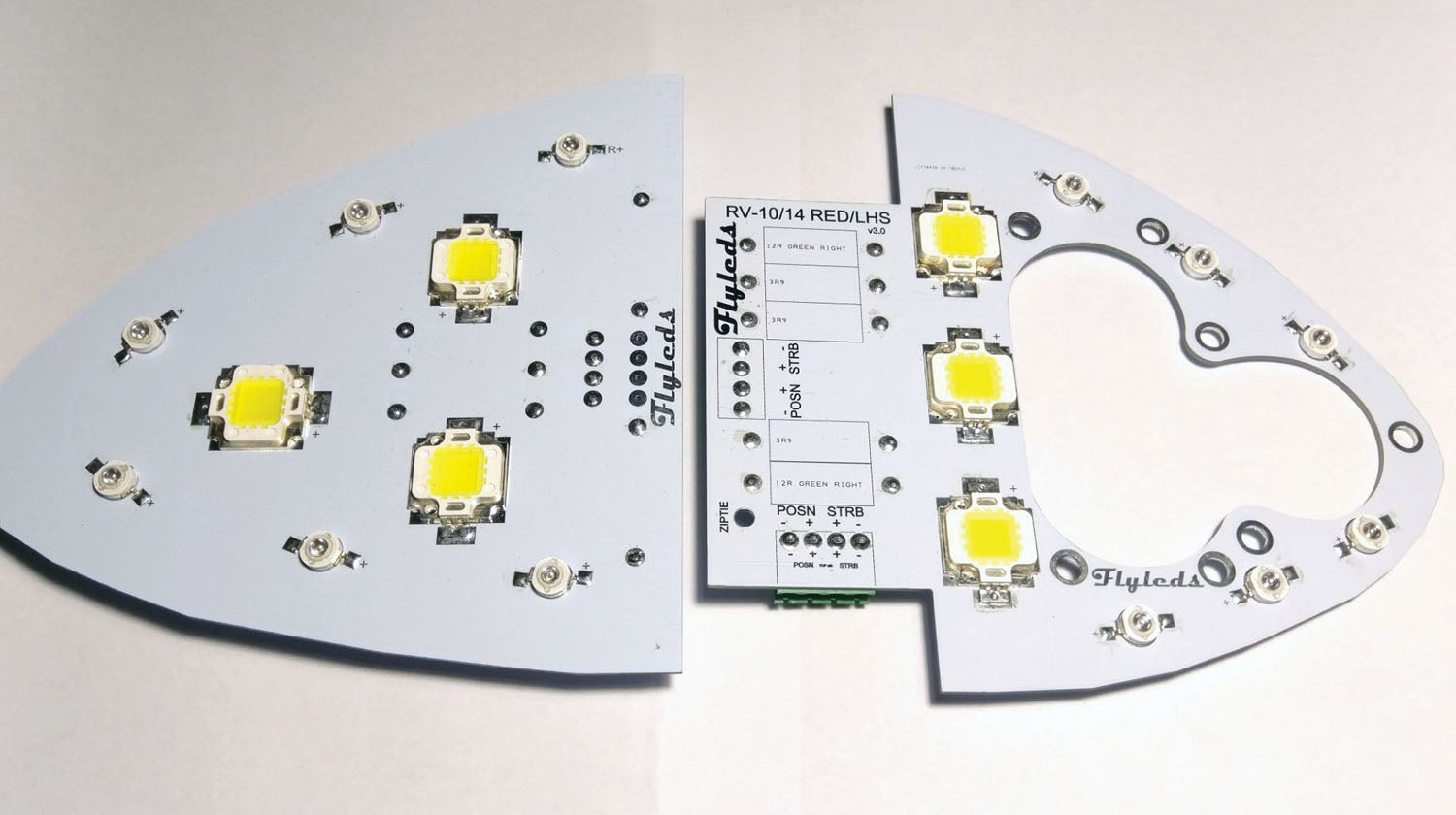
The wingtip locations are where the Flyleds system is somewhat unique. They supply a white-coated circuit board to which the soldering artist (aka the kit buyer) attaches surface-mount LEDs and through-hole resistor and connector components. When complete, the circuit boards are mounted directly to the outside surface of the old wingtips, under the lens where the landing, position and strobe lights used to be. This changes the appearance from a wingtip with light bulbs on it, to a wingtip with circuit boards. Some builders will elect to paint the circuit boards, but after contemplating the time involved to carefully mask off all the bright components and the risk of paint bleeding through, plus the additional effort if any component needed to be de-soldered for replacement in the future, I decided that the supplied white color looked perfectly fine, thank you very much!
The first step in building the wingtip boards is to shave them down to be a nice, clean match with the outline of the wingtips. The boards sand down quite quickly, so proceeding carefully and in small steps is in order. For me, this required lots of trips back and forth to a bench mounted belt sander, but probably only took about 15 minutes per tip. After soldering the controller board, the wing tips went together fairly quickly, and it was actually kind of fun to see the solder turn to a shiny, penetrating liquid and then flash back to a duller solid. I found soldering the resistors worked a little better if they were placed in the holes and then had most of their “legs” cut off. This eliminated some of the excess metal acting like a heat sink and allowed faster heat-up times for the components and their pads.
LED Landing Lights
LEDs have come a long way. Each landing light is only a single LED, mounted at the bottom of a magnifying/focusing lens. When I first saw this, doubts crept into my mind that the light output was going to be sufficient, even with two landing lights on each wingtip (the Rocket has space for only two lights in each wingtip; most other RV-types have room for three). With this in mind, I hooked up one of the landing lights to an old battery, walked out of the hangar and shined it down the runway. The reflection could be seen off a sign 2500 feet away. It wasn’t even quite dark yet. This was with a single landing light. There are four. Martha, batten down the hatches!
Speaking of batteries, the instructions call for testing position and strobe assemblies (not individual lights) with a standard 9-volt battery. This was an excellent recommendation, as even with only a little 9-volt powering things up, it took a long while for the spots to clear from my eyes. Hint: Don’t look directly at the light when testing. Duh.
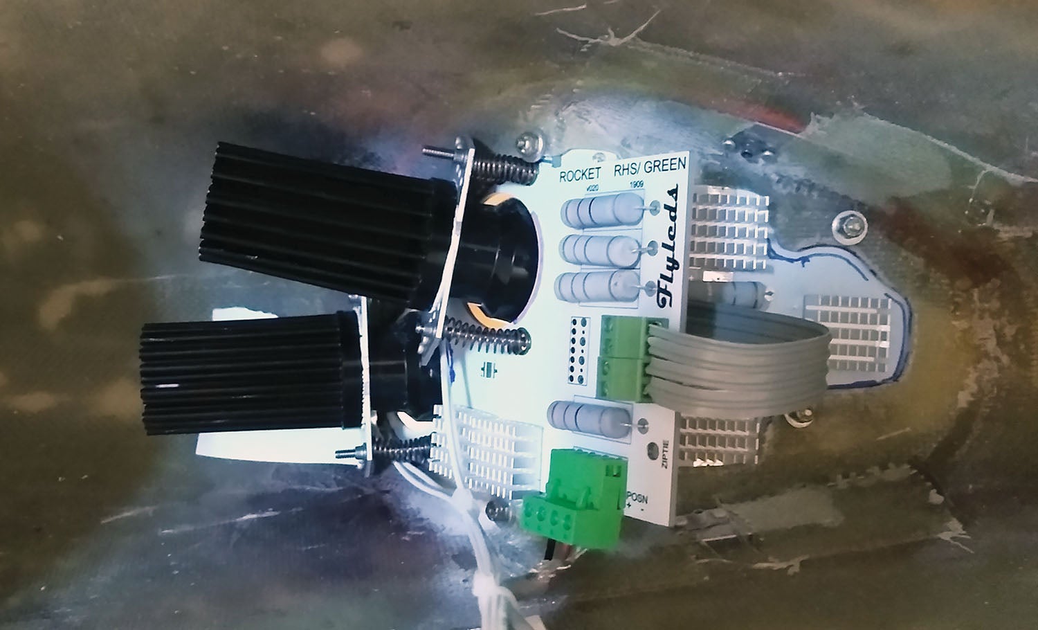
The landing lights are each installed on their own circuit board. Each landing light board is installed behind the main wingtip board, with its lens protruding through a dedicated hole. Three screws with springs allow the lights to be individually aimed after installation in the tip. This raises the question of how landing lights should be aimed. Tailwheel airplanes point skyward when sitting on the ground. In the case of the Rocket, it is about 12°. This means that if the lights are all aimed parallel with the level-flight attitude, then the runway will go dark as soon as the tail is lowered. Those of you with training wheels don’t need to worry about that.
To counter this, the lower light in each wingtip was aimed parallel to the direction of flight and the upper light was aimed parallel to the ground with the tail down. To complicate matters a bit, each of the original mounting surfaces in the airplane were canted about 15° outboard. This meant a lot of adjustment was needed to get the lights to point in the same direction as the airplane travels and with the correct vertical aiming points. Making things even more complicated, the location of the switches in the airplane meant that with the tail up on the stand (a step stool, a Home Depot bucket and a couple of blocks of wood), the light switch could not be reached from the outside, and given the nature of the tail stand, I didn’t want to climb into the airplane.
Trigonometry to the rescue! Knowing that the tail-low attitude was 12° nose up, compared to the level flight altitude, a target (masking tape and an “X” with a felt pen) could be placed at the appropriate height on the far hangar wall. To help center the targets, a laser level was placed adjacent to the tailwheel and a plumb bob hung from the spinner. When the vertical line of the laser lined up on the string on the plumb bob, the line projected on the hangar wall accurately marked the center of the airplane. Measuring the distance between each wingtip then provided the appropriate horizontal location of each target from the centerline on the wall.
Of course, this is all assuming that the in-flight landing lights should be aimed straight ahead with the level flight line of the airplane. Some might argue for aiming them slightly up, so that you can see beyond your touchdown point on final approach. However, at approach speeds, the airplane is likely to be somewhat nose-up anyway compared to the direction of actual travel, so I settled on the level flight position as being a happy medium for an initial setting prior to flight testing.
Mounting and aiming the landing lights in the Rocket flavor of the Flyleds kit took a bit of trial and error. The included mounting screws would probably work fine for many or most aircraft, but substituting one screw on each board for another one a half-inch inch longer seemed to work better and provided more adjustment. It was necessary to shave the boards down, right up to the edge of their blind nuts, in order to avoid interference with the inside surface of the wingtip and with each other. And even then, it was necessary to “screw” one of the springs in each wingtip up the adjacent board, where the spring on one board overlapped the edge of the other board. It was also necessary to slightly elongate the landing light lens holes to eliminate some interference. All that being said, none of the adjustments were a big deal, and all were the kinds of things we homebuilders do all the time during the building process.
Switch Panel Changes

Part of the project involved installing a new floodlight switch. The Rocket’s switch panel was a bit tight, but using a two-position switch allowed for an existing switch hole to be reused. It now has two switches controlling all of the lighting: Both of them are 2-10 two-position switches. The first switch turns on the position lights only in the first position, then position and landing lights together in position two. The second switch turns on the floodlights only in the first position and then the strobe lights only in position two (see Bob Nuckoll’s AeroElectric Connection book for an excellent reference on how to wire these switches for different functions). This makes for a nice, tight installation (without wigwag control), albeit with a requirement to relabel the old switch panel. The switch panel itself was produced by Front Panel Express, an online service that provides a free CAD program to allow the user to design their own panel, complete with engraved or screened lettering. Then just push a button, and the real-life panel is delivered to the mailbox a few weeks later.
Does “The Works” Work?
While the kit was very complete (including extra position lights, screws and blind nuts in case of an “oops”) and well labeled, and the project was fun, the real test comes with flight in the dark.
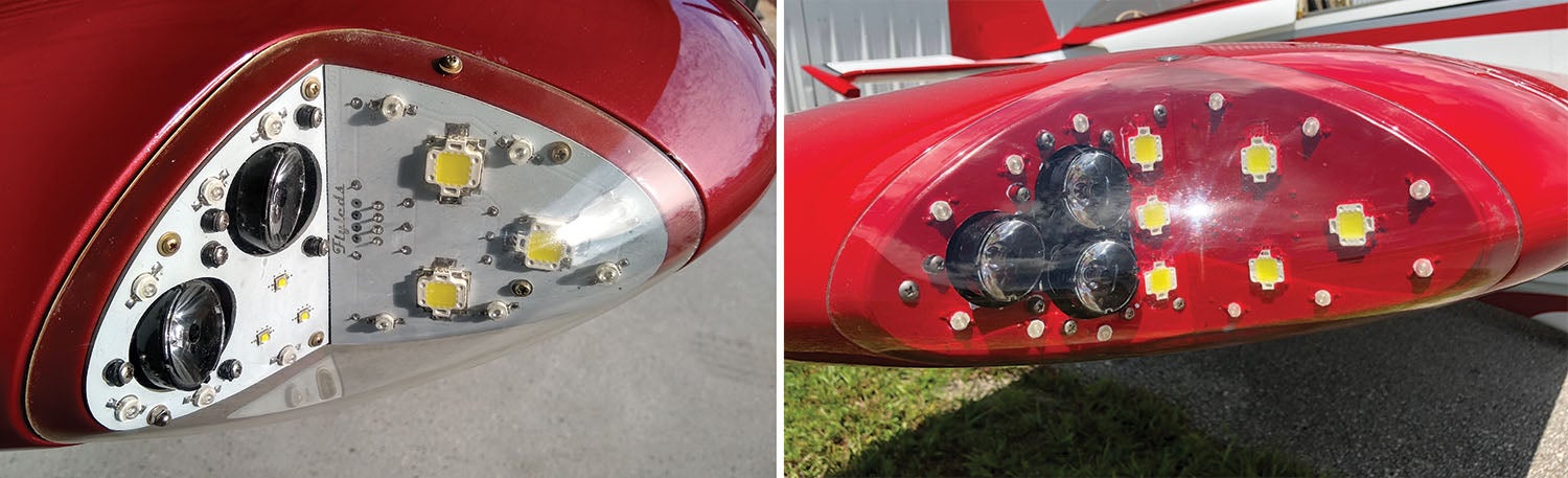
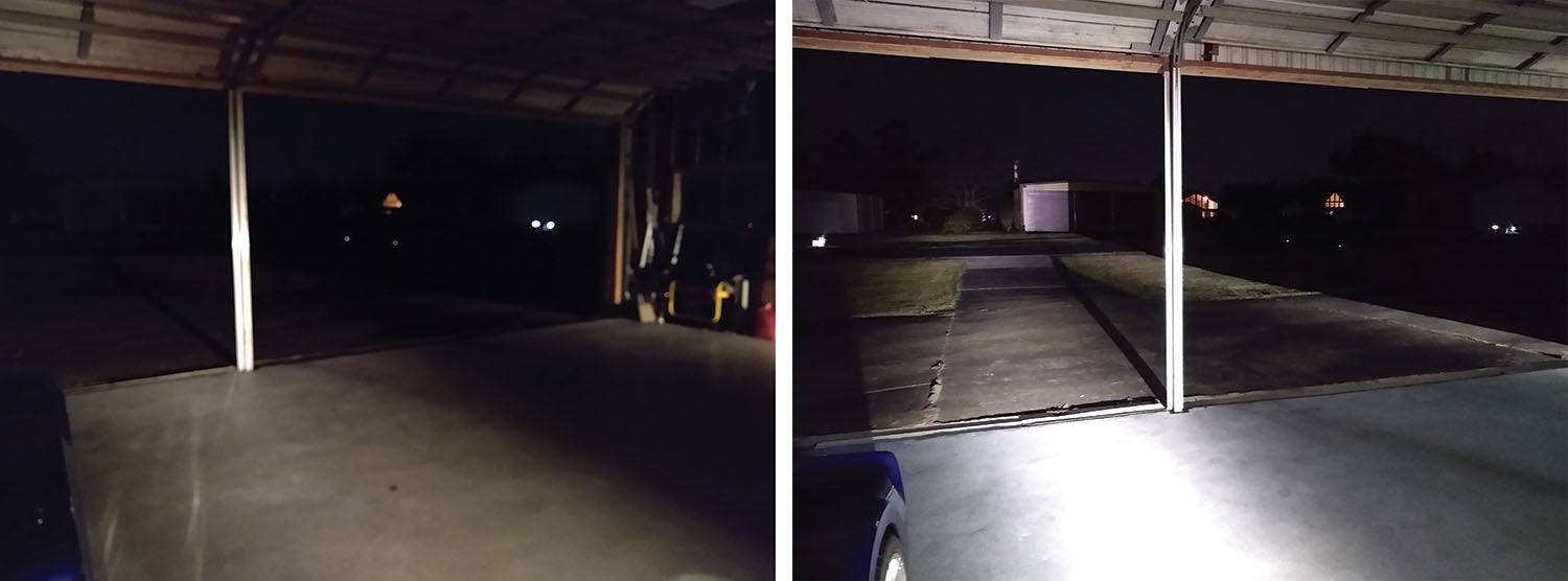
Before upgrading, the old 75-watt halogen lights were tested by turning them on and taking some pictures. A dull glow was cast on the hangar on the other side of the runway. After upgrade, the same hangar was lit up like a spotlight, and it was possible to cast shadow puppets on the trees in the yard behind it (see the “crazed gazelle” reference at the start of the article). The new position lights were significantly brighter than the old incandescents. I’m not sure about the strobes, but I’m pretty sure they were brighter as well, based on the reflection from objects around the airplane. The floodlight setting on the strobe LEDs was particularly helpful for illuminating the ground to the sides of the airplane and helps to spot a taxiway or ramp turnoff. With the floodlights turned on, the landing lights can be kept off during taxi as the floodlights cast more than enough light in front of the airplane as well.
In the air, the new landing lights did a good job of lighting up the numbers while still a few hundred feet up on final approach, and the sides of the runway in the landing area were clearly visible. Witnesses on the ground reported that the airplane could be seen from a long distance away, and another aircraft joining the circuit reported me in sight while he was still behind me and several miles out of the circuit pattern. Another pilot/owner on the field called up and asked what kind of lights I had upgraded to, as he now wants a set of his own.
It should be noted that the Flyleds Rocket kit includes only two landing/taxi lights per wingtip. Other RV-style aircraft have more room in the tips and can fit three. There are also versions available for leading edge installations and even a PAR36 replacement with a whopping seven lights contained within the assembly, which ought to be enough output to work as x-rays in a pinch.
If your old lights are questionable, the new LEDs have evolved to the point where they are hard to beat for performance, longevity and price. If you are considering an LED conversion for your airplane, the Flyleds kit ought to qualify for your list of contenders.


The U.S. distributor for FlyLEDs is Blake Frazier at https://www.flyboyaccessories.com/
Comments are closed.