For many years, I flew a homebuilt airplane with a Lycoming O-360 narrow-deck engine that was built and first flown in 1972. Several years ago we switched the case to a wide-deck version. During the 14 years that I have been flying the plane, both of these engines required teardown and rebuilding. Even with an interest and background in doing mechanical work myself, I was surprised at how difficult it was to separate the engine case halves during a teardown. I have been studying this problem and have learned a few things from the Internet and through talking with Allen Barrett at Barrett Precision Engines of Tulsa, Oklahoma and Harold Harris of Crankcase Services Inc. of Sand Springs, Oklahoma.
By the Book?
The Lycoming Engine overhaul manual has a section related to separating the case halves in section VII on pages 7-13. This page is dated January 1971 and is titled Separation and Assembly of Doweled Crankcases. The photographs in the overhaul manual depict a mechanic using Lycoming Tool #ST-122 Crankcase Pressure Plate. The Lycoming Special Service Tool Catalog describes this tool as appropriate for “all engines employing crankcase thru stud dowels.” An Internet search for “separating Lycoming engine cases” found an excellent article—with many photos of an engine teardown—by Matt Throckmorton (DocThrock). His engine is a Lycoming O-540 wide-deck engine, which does not have “thru stud dowels” in the crankcase, yet he was using Lycoming Tool #ST-122. This confusion caused me to spend some time researching all of the different combinations of engines and which tools are appropriate.
Decks, Bolts, and Studs
I found that there were three different types of engines. The first were what is commonly referred to as narrow deck. Narrow-deck engines had flanges on the cylinder bases that were relatively thin. The flanges were reinforced by plates installed under the cylinder hold-down nuts and were curved to cover approximately half of the cylinder flange base. The cylinder hold-down nuts are internal-wrenching (like a twelve-point Allen wrench socket head cap screw). The diameter of the circle of bolts and studs that anchor each cylinder was slightly smaller on the narrow-deck versus the wide-deck engine. The through bolts on these engines were threaded into one side of the crankcase. Because they were anchored by being threaded into the case, they were referred to as “studs.”
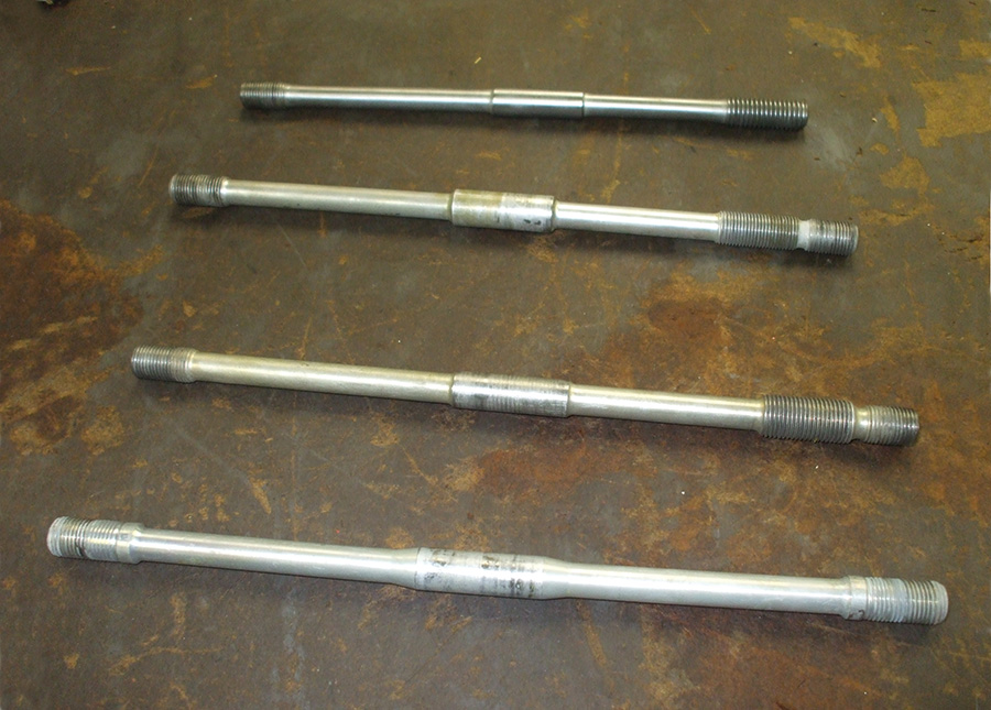
There are four different types of through bolts or studs used by Lycoming over the many years that they have been manufactured (see Fig. 1).
The top bolt in Fig. 1 is called a case bolt. The left side of this bolt has ½-20 threads to secure the flange of a cylinder. The right side has ½-13 threads and is installed at both the front and rear through bolt positions on a narrow-deck engine. The coarse threads are used to anchor this bolt to one side of the case. This same bolt is also used on the two aft positions of a four-cylinder wide-deck engine.
Lycoming started to make changes to their engines to improve them to what is now called the wide-deck engine in the mid 1960s. This process was completed in the ’70s. A few changes generated what could be referred to as a “mid-deck” engine. The through bolt second from the top in Fig. 1 is from this era. It is a stud installed in the center position on both four- and six-cylinder engines before the issuance of SI-1123C. This stud has an enlarged center of 9/16 inch in diameter. This was an attempt to stop crankcase fretting. Notice that the right end of this stud has two sets of ½-20 threads. The threads on the extreme right end are for the cylinder hold-down nut. The threads further from the right end are to secure the stud to the case half.
Lycoming Service Instruction SI-1123C was a modification to the center through bolt positions that called for a counterbore in both case halves to accept a hollow dowel. The through bolt would pass thru this dowel. This service instruction rendered the second through bolt in Fig. 1 obsolete. The third stud in Fig. 1 has a reduced center diameter from number two, to allow it to pass through the new dowels. It also had an enlarged thread on the right end to anchor it to one side of the crankcase.
All three of these studs are anchored to one side of the case and therefore cannot be pushed or pulled all the way through the case. Lycoming’s tool #ST-122 for separating engine cases is a pressure plate that pushes on these studs from the far side of the case. Lycoming has not manufactured an engine with this configuration since the mid ’70s.
The fourth bolt in Fig. 1 is the one used on wide-deck engines. The center of the bolt has a ½-inch diameter, and is designed to be a close-tolerance fit on the case halves at the split line. This “body-fit” was adopted to prevent movement of the case halves relative to each other and thus prevent fretting. All eight of the through bolts on a six-cylinder engine are this type. The rear two through bolts on a four-cylinder engine still use the case bolt in position one of Fig. 1.
My description of all these different through bolt designs has been leading up to a discussion of how to disassemble a Lycoming crankcase.
Taking it Apart
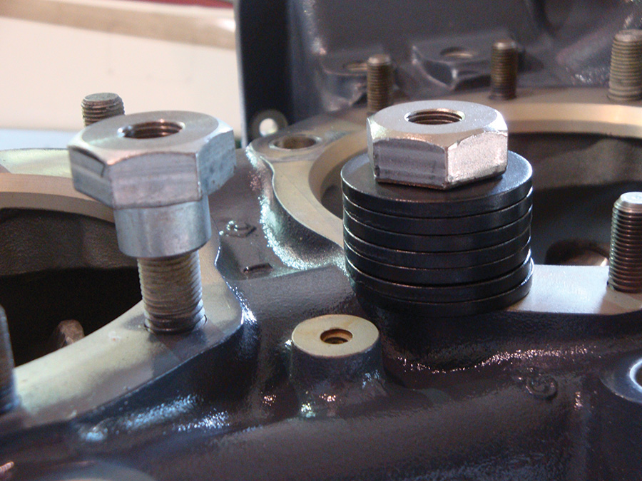
If your engine is a wide-deck version, the through bolts that are not anchored to one side of the case can be removed first. This is done by threading a nut onto the through bolt with a stack of washers under the nut (Fig. 2). The nut that we use has a longer length than the standard cylinder hold down nuts. This gives us more thread engagement to prevent wearing the through bolt threads. As the through bolt is withdrawn, the stack of washers must be increased in height. All eight of the through bolts on a six-cylinder engine can be removed in this way. The front four through bolts on a four-cylinder engine can also be removed in this fashion. Removal of the through bolts greatly decreases the forces involved in splitting the case apart.
The crankshaft seal at the front of the case is glued in place with Pliobond. Unfortunately, this can make the case difficult to separate because the seal will be holding onto both sides of the front of the case. This can cause a misalignment during separation of the halves that could damage the oil slinger on the crank. The front seal should be carefully removed from the nose of the case. Be very careful not to scratch the crankshaft surface that the seal rubs on during rotation.
At this point, Lycoming Tool #ST-122 cannot be used because it relies on the through bolts to force the case halves apart.
I asked a few shops how they separated wide-deck engines and found that they used in-house, custom-designed tools. Since I couldn’t find these tools, I decided to build a set for myself.
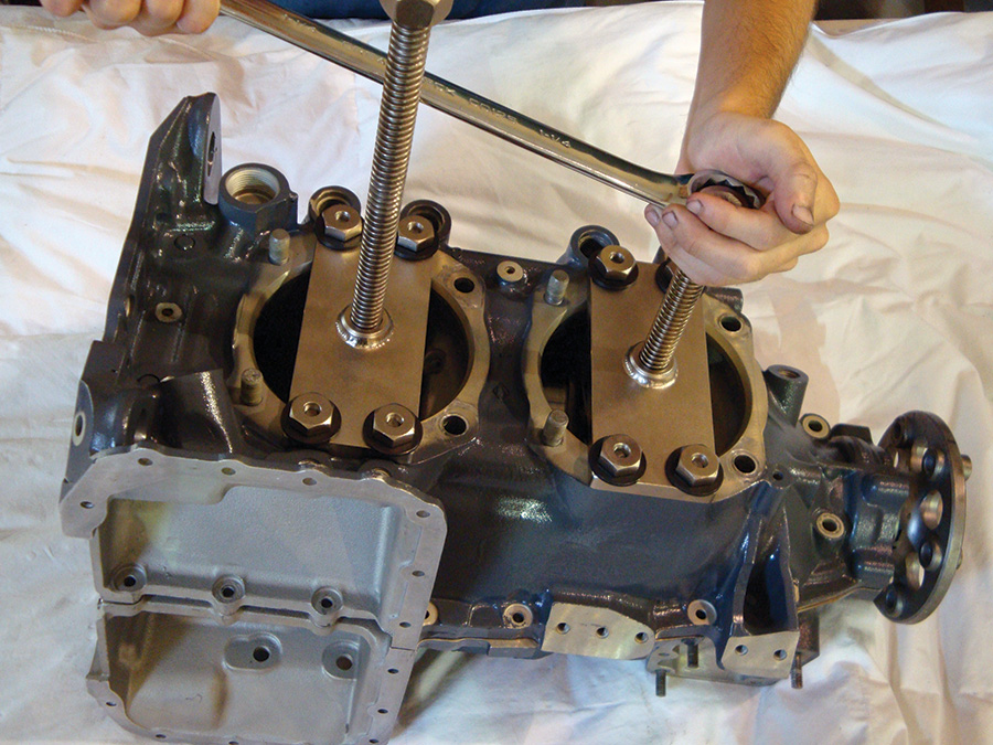
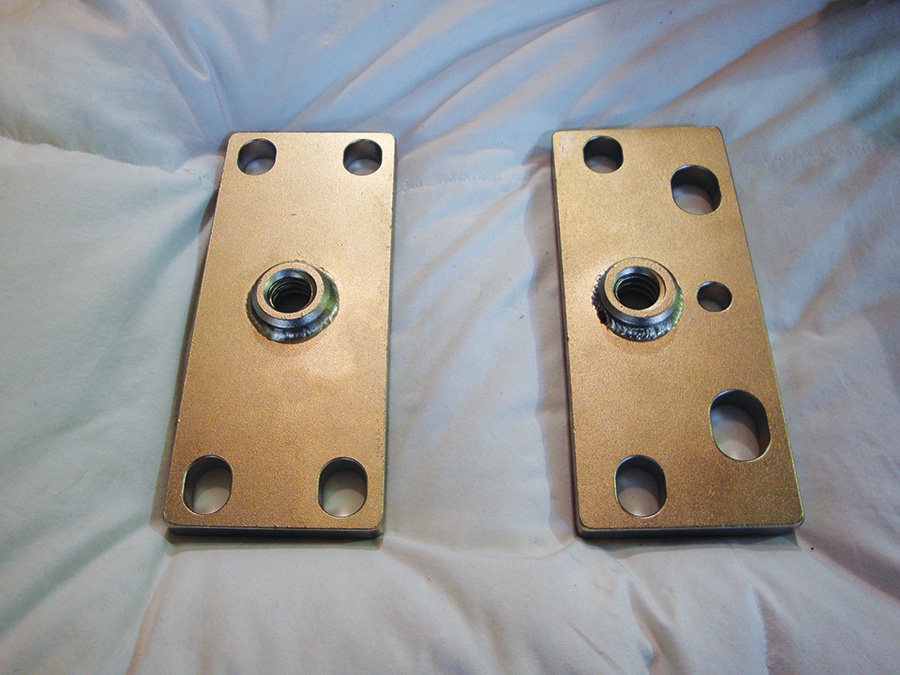
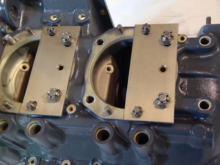
Fig. 3: Plates can be used over the cylinder base holes to provide anchors for the case-splitting screw.
A Tool is Born
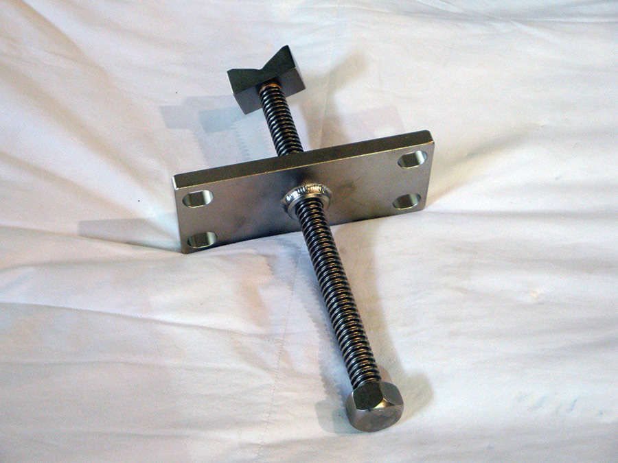
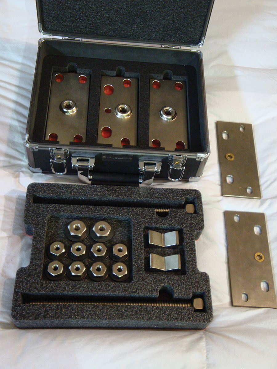
My design works by attaching plates over the cylinder base holes using hold-down studs (Fig. 3). The plates have Acme threaded nuts to accept a large Acme threaded shaft with a V-block. This block can then be used to apply force to the connecting rod journal of the crankshaft (Fig. 4).
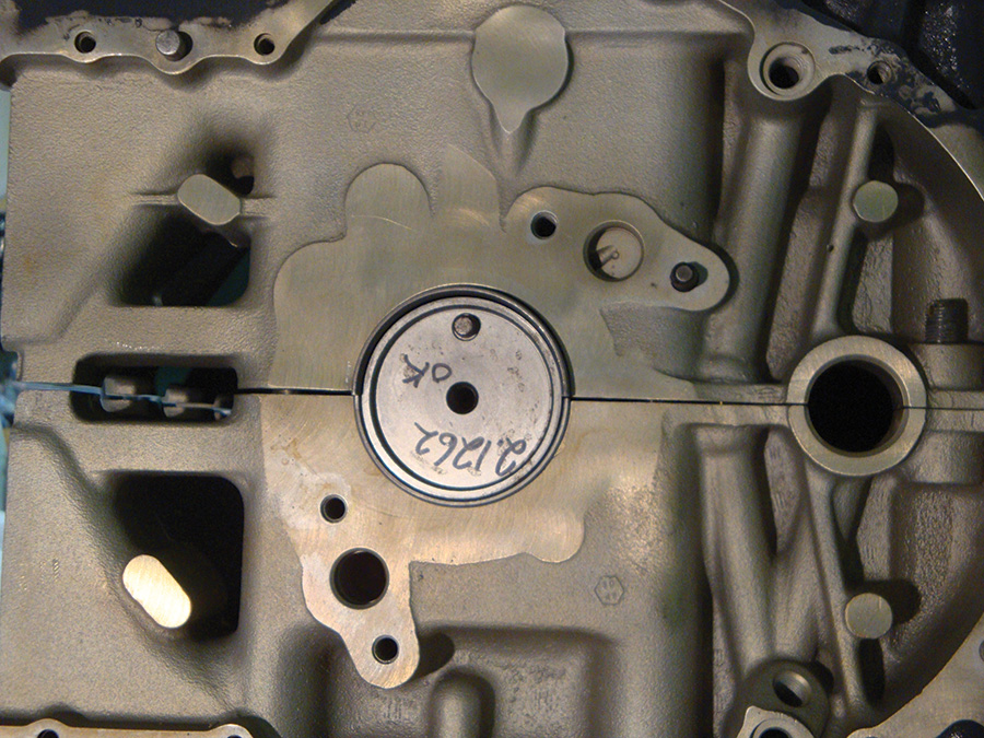
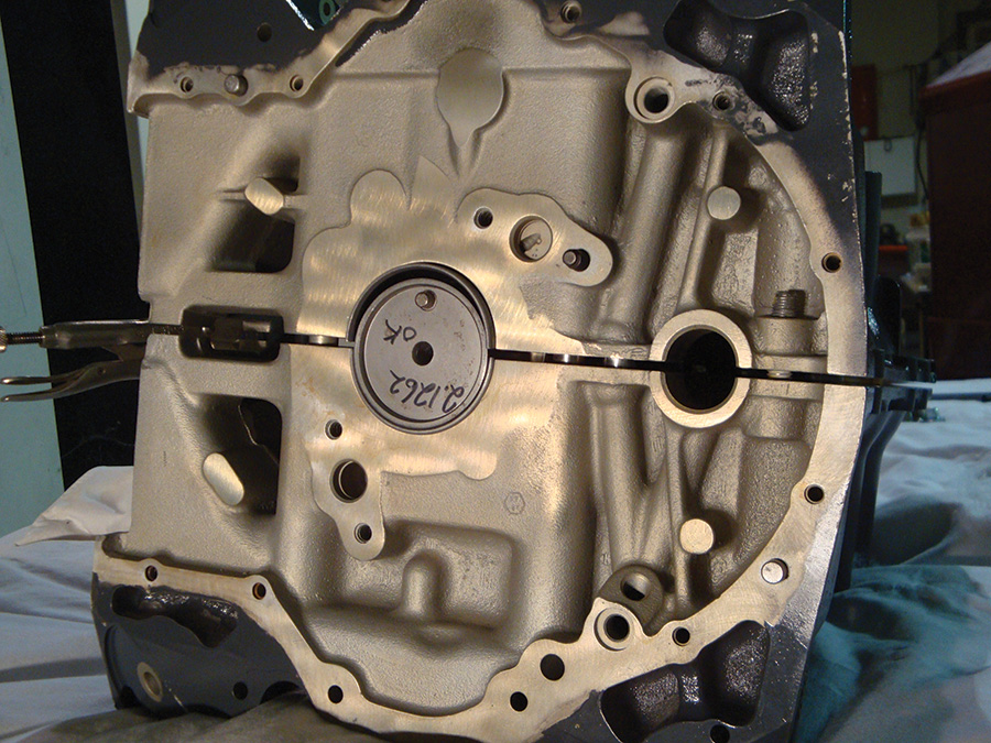
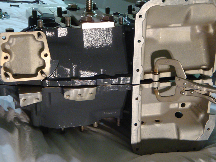
During the separation, the case must be monitored in two planes and kept parallel (Fig. 5 and Fig. 6) because Lycoming engines have an assembly pin that press-fits into both case halves in a different location from the through bolts (Fig. 7). These pins are not symmetrically located relative to the crankshaft. This means that the case halves will attempt to rotate around the crank during the separation (Fig. 8). To control this rotation, a clamp can be used to keep the case halves parallel as they separate (Fig. 9). During the case separation, the force required is a result of any remaining through bolts, the assembly pins, and the sealants used along the split line during assembly.
Variations on a Theme
All Lycoming engines are similar, but not identical. Likewise, they require similar, but not identical, plates to split the case.
• On a four-cylinder engine, the crank journals are all in the same plane. One threaded shaft and V-block will press on the near journal and the other presses on the far journal. This engine requires two symmetric plates.
• On a six-cylinder engine, all of the crank journals are 60 degrees apart. This only allows pressing against one journal. Pressing on another one causes the crank to rotate, forcing the two case-halves to twist as they separate. The solution is to push on one crankshaft journal and one counterweight mounting “ear.” So, this engine requires one symmetric plate and one assymetric plate (See Fig. 10).
• On an engine case assembled without a crankshaft, the case-halves need to be pushed apart without the crank. The solution is to mount a second plate on the opposite side of the engine using the cylinder hold-down studs. Because the cylinders are staggered from each other, the opposite cylinder hold-down hole is not in line with the opposing cylinder. This requires yet another specially designed plate, and it has a bearing that is located in-line with the screw from the opposing cylinder (Fig. 11).
Tearing down a Lycoming engine is one of those projects that can have extremely serious consequences if it’s not done right. Like so many other aspects of maintaining a homebuilt aircraft, the results are always better when you use the right tools—even if you have to make those tools yourself.
For additional information, contact Richard Keyt, Ryan Machine, 9608 Taxiway Dr., Granbury, TX 76049, 817-573-2786, [email protected].





Where do we find ordering info on that case splitter tool kit?
Have you tried contacting the author via the phone or email listed in the article?
Looking for a part number. We had a thru stud sheer off and have removed the stud. Engine is an IO-360-A1A. The bolt is the top one that holds cylinder #3 and #2. Upon removal, we see that the bolt has the larger threaded section that screws into the case on the right side. The standard Lycoming part number spec’d here (76220) does not have the threaded insert. We are looking for the part number of the stud with the larger threaded section. Any assistance would be greatly appreciated.
Perhaps part number 69679. That whats in my 360 A1A, are you able to remove the thru bolt without splitting the case ? I figured with it being threaded into the right side of thhe case you cannot remove it without opening the engine.