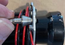
Hammer to shape, file to fit, paint to hide.” You could reasonably conclude that this is the factory motto if all you read was the instructions for fitting the nosewheel on my current project aircraft. The spacer is, I assume, intentionally too long, though why it should be is a mystery. However, the factory, quite correctly, points out that this will result in inappropriate side loading of the bearings and diminished life.
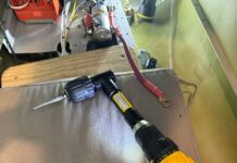
The factorys solution? “Grind it off.” And to emphasize what the company means, the manual shows the use of a heavy-duty, industrial grade, 90 grinder! It hearkens back to that hoary old definition of a professional mechanic versus amateur: The former has a greater selection of hammers. I suppose if you didn’t have any other method available this would have to do. Obviously, it works. But we, the home machinist types, do have an alternative: the lathe.
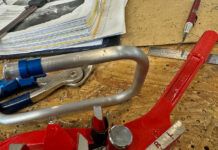
First, lets carefully examine what we want to accomplish. The builders manual says that the spacers should not extend beyond the wheel hub. So I placed the hub on a small, flat steel block and gently tapped everything down. I say gently, because were dealing with bearings; they can carry quite high rolling loads, but a hammer is a load spike that can brinell a bearing faster than a seal going after a slice of fish. If you don’t believe it, push a hammer onto your thumb; now take a very light swing at your thumb. Like Oscar Wilde said, “The things that are really worth learning cant be taught.”
I hear someone out there saying, “Baloney! [Or something more flavorful, I suspect.] If that were true Id never be able to drive my car through a pothole.” My response to that is to invite you to remove the rubber tires from the steel rims and change out the springs and shock absorbers for a set of low-rider hydraulics. With all that shock absorbency removed, go see how long the bearings last. Conversely, if you want to offer up an equivalent cushion, put your thumb on the bearing and then start hammering away; the bearing will survive quite nicely.
Back to the spacer: How much do we need to take off? You sure cant measure over the wheel to the other side very easily, but with an inexpensive, general-purpose digital caliper you can directly measure the material to be removed. The trick to using one is to keep it perpendicular to the surface.
Using the Caliper
There are two ways to measure the offset using a caliper. The first, and most common technique is to use the extending rod at the end of tool. As you open the gap between the jaws, the rod extends in perfect synchronicity. While a dedicated depth micrometer is the ideal tool for measuring the depth of a hole, a good caliper will do an acceptable job of it. The advantage of the dedicated depth micrometer is that its broad base gives you a better shot at achieving perpendicularity. The problem, for those of us on a budget, is that they have a 1 inch range. You therefore need a kit comprising a base and six rods to do what the caliper can do; the micrometer will only measure depth.
If clearances allow it, a second method that comes closer to that perpendicularity goal is possible. Where in the previous method you could swing the tip of the rod in a circular orbit without knowing it, the caliper has a function that employs a larger base, minimizing that orbital movement. Why? Quicker, better results.
We see that we need to take 0.032 inch off of the material. While were at it, get into the habit of putting a zero out there as the leading figure. It makes for less confusion when you have a dimension with a leading zero. OK, back to the project. We need to take off 0.032 inch from the end, so we set the part in the three-jaw chuck of the lathe and, because were going to cut across the face from the outside to the center, we select a right-cutting tool.
We are going to cut across the end of the material, so we need to set up the tool so that it cuts through the centerline of the material. How to do this was described in an earlier article, but its such an easy and yet essential part of using the lathe that well go through it again.
Position the tool so that the cutting point is not quite touching the material diameter and lightly lock it down. Now put a 6-inch steel ruler between the tool and the part, and crank in the tool just enough to hold the ruler against the part. Don’t overdo this; you don’t need any more force than the minimum needed to capture the ruler.
Is the ruler vertical? No? If the top of the ruler is leaning towards you, the cutting tool is below the center of the part; leaning away, its above center. All you need do is back away from the material, adjust the cutting tool up or down to get the ruler vertical, and try again. The vertical positioning can be done by using shims under the tool, or better still, assuming your equipment has this feature, by turning a knob that positions the tool holder in the Z axis. If its not on center you wont get a good surface finish and, when you cut across the end of the material, you’ll leave a nubbin of material that looks ugly. There are times when you want to have the tool about 0.005 inch below center, but thats a little too advanced for us right now.
Now we have to position the tool to cut the face, so pivot the tool assembly around so that the tool point is about to touch the end of the part and the cutting edge is facing to the right. Finally, remember to tighten the tool down. If its not secure, you could get a nasty surprise.
Also get into the habit of removing the chuck key from the three-jaw chuck. Either your hand is on the chuck key or its out of the chuck. Neglect this and, if you’re lucky, the key will be thrown across the shop when you hit the start button; unlucky and itll whack into the lathe bed ways making all manner of expensive noise; really unlucky and you’ll get an even more expensive visit to the dentist when you wind up eating it for lunch.
This is aluminum, and a pretty small part, but well still check for feed and speed. Use any of the reference books you like, but at the moment I am looking at
Machinerys Handbook – Pocket Companion. It tells me that a turning operation for aluminum should be done at 500 surface feet per minute. Another chart within the book converts that to 1910 rpm for a 1-inch diameter bar.Having set that speed, we need to take a measurement from some fixed reference point. Conveniently, we can use that step function on the caliper and measure the change of extension as we cut. Simply set the calipers steps with one on the end of the material and the other on the jaws of the chuck; push the button on the caliper to set it to zero.
Now, lets get a bit clever. Move the jaws of the caliper together until they read 0.039 inch, and push the zero button one more time. Now all you have to do is cut off material and measure. When the caliper reads zero, you’re there.
Lets start with a minimum cut-just a few thousandths will do to make sure that everything is tightened down. Next, stop everything without turning either the X or Y axis handwheels, and then set the handwheel dials to zero. You can now move right (+X) and back out (-Y), restart the jaws turning, and then run the handwheels back to zero. You’re back where you started, and you know it because the dials say so.
Just remember to always go past zero at least half a revolution before you come back to your mark. This is necessary to take the slack out of the gearing on the handwheels. Neglecting to do so is the most common source of errors when doing any machining, so burn this procedure into your mind.
Here comes the fun part. Move to the left (-X) until the dial reads 0.010 inch and take a cut; stop and measure it with the caliper. Youll remember that we set up the caliper so that it would read zero when we got to the right length. We started with 0.039, and assuming we took 0.004 inch off on the first cut and 0.010 inch off on the second, our caliper should now read 0.025 inch.
In fact, you could work it backwards as well. It started off at 0.039 inch too long, and we know that the second cut took off 0.010 inch; in fact, the Y axis dial reads 0.010 inch. The caliper tells us we have to cut off another 0.025 inch, so that first cut had to be 0.004 inch. Thats the fun of this little trick: you only have to do the math once, and then you just count down to zero. Im cautious, though, so I would take another 0.015 inch and then 0.010 inch so as to get a better finish.
Familiar with the Machine
Although were not using the function here, I want to point out something that can really bite you if you’re not aware of it. The dials that indicate X and Z axis travel, that is to say left-right and up-down, are direct-reading. If you move the dial 0.030 inch, the tool will move 0.030 inch. However, the Y axis, in-out, is not the same on all machines. On my machine, if I move it 0.030 inch, the tool moves 0.030 inch. Seems reasonable.
If Im taking a cut on the diameter of the material Ill have a part that is 0.060 inch smaller on the outside diameter. Thats because Im cutting the radius, but measuring the diameter. Being aware of it means that if I want to reduce the OD 0.030 inch, I have to move the dial 0.015 inch. For that reason, some machines are set up to move the tool half of what the dial indicates. Whenever you work with a new machine, test this to find out which system is built in.
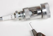
Finish off with a touch of a file to the outer edge, and then put a small chamfer on the inner edge. Why? Sharp corners are easily mashed over to create burrs and undersize holes. The inside chamfer is easy to do if you fit a large conical deburring tool into a file handle, and then just lightly touch the inside.
Well, thats it. Our first lathe project was substantially more complicated, but this one helped develop some sophisticated skills. In future articles well detail the use of the boring head and describe work being done between centers. Well show the use of a moving rest that will allow you to reduce the diameter of long, skinny parts that, without a moving rest, would simply flex away from the tool. Well also show how to chuck up a non-symmetric part and then bore a hole in it off center.
For now, sweep up the chips and wipe down the entire machine. Itll pay back by making the parts easy to build, and the machine will last a long time.
Editors note: If you have specific questions for author Bob Fritz, or if you have certain projects youd like us to cover, email us at [email protected] with “Home Machinist” in the subject line.

