
A while back, KITPLANES® web guru Omar Filipovic paid a virtual visit to the Home Shop Machinist. He had been chasing down sources for cable clamps for a 1960s-era autopilot made by Century Flight Systems (CFS) and had come to a dead end. The clamps were, as Omar mentioned, a topic of discussion on the Glasair Aircraft Owners Forum, which, it turns out, is another website Omar runs.
He asked if I would take a look at photo examples and think about how to make them.
While the clamps looked pretty simple, originals have been difficult to come by. I was not familiar with the CFS autopilot, but I was able to find some information on the internet, including CFS installation assembly drawing 69D508 dated 1965.
From a machinist’s point of view, the clamp couldn’t be simpler: A couple of grooves, some bolt holes and you’re done. From an engineering point of view, there are a couple important details to consider that could be critical to safety.
The first detail is the length of the clamp. At first glance, this may seem like overkill. A single 1/4-28 bolt should be more than sufficient to securely clamp two cables together. There are dozens of examples where single-bolt clamps are used to secure brake cables, winch cables and the like.
But when you take a step back to consider what’s going on, the reasoning behind the design becomes clear. By distributing the clamping pressure over a longer span, they’ve created a way to clamp to a flight control cable without damaging it. Unlike brake and winch cables, which are designed to work under enormous tension and withstand crimping, flight control cables are not. They are designed to be flexible enough to bend around pulleys and pass through fairleads. The ends are usually terminated with a swaged fitting, such as a fork or turnbuckle. They are rarely, if ever, pinch clamped.
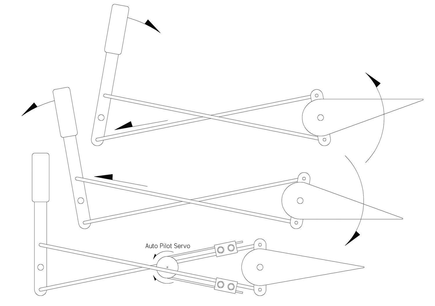
CFS autopilot is relatively simple. A servo-driven capstan drives a small cable, which is clamped to the main control cables.
The second detail to note is the smooth radius where the cable exits the clamp. One of the first lessons in engineering is that sharp corners are stress risers that can initiate fatigue failure. By softening the edge of the clamp, you prevent the strands from chafing and avoid possible cable failure.
The angle at which the cable pulls on the clamp is another reason why having a soft edge is important. The ideal would be to have the autopilot cable as perpendicular to the clamp as possible. The straighter it comes out of the clamp, the less fatigue there will be on the cable. It’s likely this angle will not always be perfect. In fact, on the CFS installation drawing I mentioned earlier, it shows the autopilot cable coming out of the clamp at an angle of about six degrees. So every time the controls are moved—regardless of whether the autopilot is engaged or not—the autopilot cable is in fact bending back and forth, however slightly.
Three-Bolt, Two-Bolt and Poka-Yoke
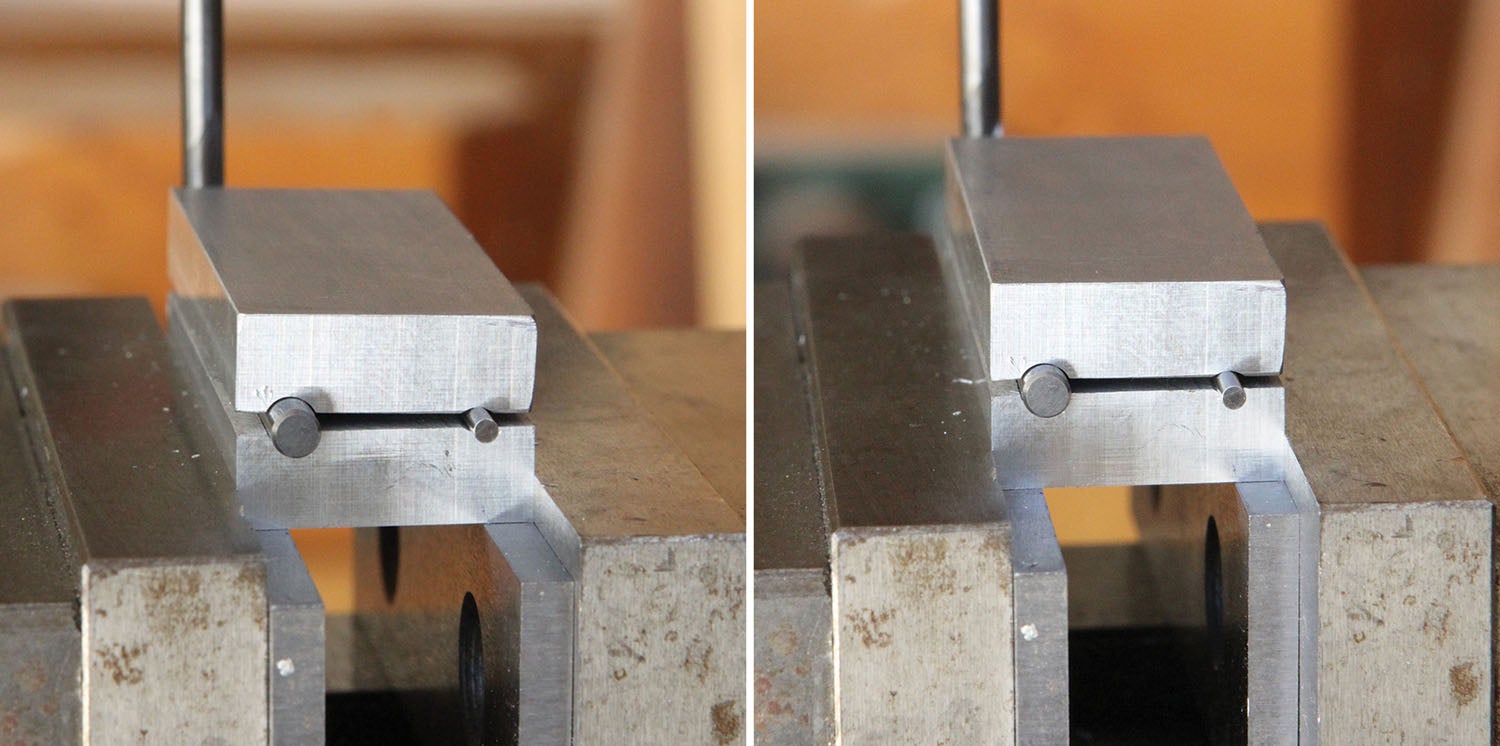
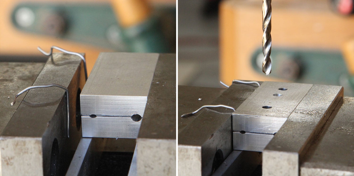
I ended up making a couple different versions of the cable clamp for Omar to test. The first set was more or less faithful to the original three-bolt style shown in the CFS drawings. I made these in three steps: sizing the blank, drilling all the holes (including the cable clamping slots), then slitting the block in half. My thinking was this would be an easy way to line up all the matching holes and slots. While the concept seemed sound, it turned out that deep-drilling a perfectly straight hole with a 1/16-inch twist bit, even with careful peck-drilling, was not possible with my setup. For starters, the 1/16-inch twist bit was not long enough to go all the way through the 1-7/8-inch clamp length. So it had to be flipped end-for-end with the hope the two would meet in the middle and be lined up. No such luck.
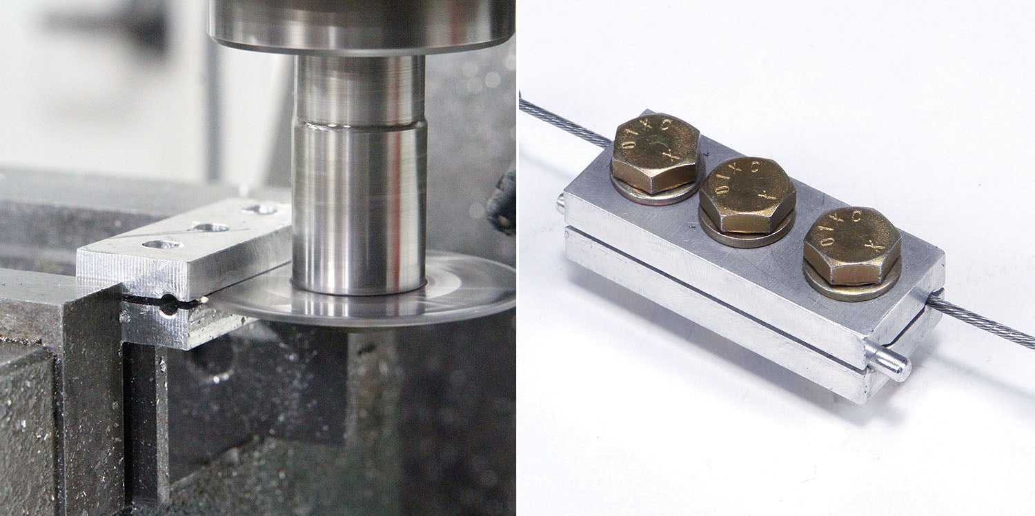
After slitting the clamp into two halves, it was apparent that both 1/16-inch holes wandered off-line just enough to be obvious. The 1/8-inch slots for the main control cables, however, were flawless. I was able to drill them all the way through with no wandering.
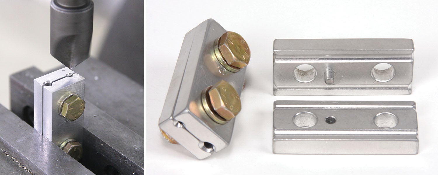
I used a knife edge file to even out the groove where it drifted off course. That fix, coupled with the length of the clamp body, gave me no doubt an autopilot cable could be securely clamped and be safe to use.
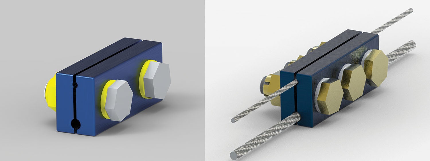
One thing about the design that gnawed at me was that during the process of checking the fit and clamping clearances (to be effective the clamp must have an even gap on both sides when tight), it was possible to assemble the clamp backwards and end up with the two grooves mismatched.
While this may seem unlikely and an obvious error, we have to consider that possibility. There are a number of ways to address this issue, such as placing the clamping bolts slightly off-line or out of phase, or adding an assembly tab or indexing pin. The concept is referred to as poka-yoke, which is a Japanese expression that means avoiding an unthinkably bad move. In product design it more typically translates as simply “mistake-proofing.”
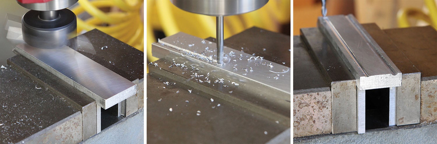
About the time I was finished with the first set, Omar mentioned a GlaStar builder who had good success milling the grooves for the cables with a ball end mill. So I sketched up a two-bolt design with a poka-yoke feature and used 1/8-inch and 3/32-inch ball end mills to make the respective cable grooves.
The cable grooves were milled to a depth to provide a 0.040-inch gap between the clamps when tight. You’ll notice this specification made for a very shallow groove for the 1/16-inch diameter autopilot cable. In practice, this proved to be sufficient to keep the cable lined up in the slot and facilitate assembly.
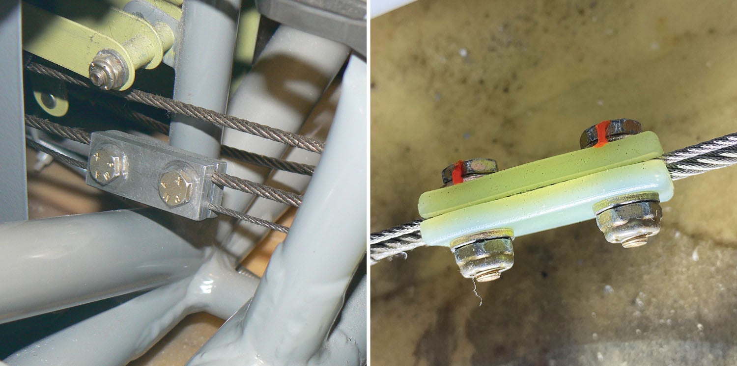


I think TruTrak ‘recalled’ those plastic clamps; because they were having problems. I would never use them.
I was the guy Omar was talking to on the forum 🙂 I made the grooves deeper than you show so the clamps came very close to touching on the 1/8″ side and did touch on the 1/16″ cable. Because the 1/16 didn’t need to have any force on it with the beaded end on the cable. During my annual inspection my mechanic made me take one of the clamps off so he could check for wire damage; but could not find any. Nice article.
Those cable clamps are very familiar to me as I spent a LOT of time in the belly and tail cone of certified airplanes setting or maintaining autopilot bridle cable tension. Due to space restrictions they never had turnbuckles to allow adjustment after setting the main cable tensions. Those clamps did NOT have a rounded groove when new. The groove should be a V groove and be shallow enough to properly clamp the cables and prevent slippage. If the clamp slips once it is useless and must be replaced. This is because slipping rounds the groove and proper clamping can no longer be achieved. Any avionics technician with autopilot installation or maintenance experience can verify this.
Please, where can they be ordered, the originals are impossible to find … (Garmin, S-tec, Avidyne, Etc.)
Comments are closed.