In last month’s article exploring the art and science for terminating wires, we discussed mechanical crimps that strive for a gas-tight connection between wire and terminal. In this article, we’re going to look at solder, a metal-joining process that pre-dates anything remotely electrical in nature by hundreds of years.
Welding or Soldering?
Using heat to join pieces of metal can be accomplished in two ways: Welding calls for actual melting of work pieces for the purpose of merging them at the joint. Material in the joint is often augmented by wire or rod of an alloy similar to that of the workpieces. Intuitively, the nature of a weld is pretty easy to grasp.
Soldering involves no melting of the work pieces, but there is an alloying activity at the interface of the solder and workpiece. Molecules of the workpiece material are physically dissolved into liquid solder, much like sugar dissolves into water.
Joining without melting the workpiece can be accomplished with a wide variety of solders. This Wikipedia article describes dozens of solder alloys, along with their specialty purposes. Brazing is a higher temperature (and stronger) form of soldering. For the purposes of our study, we’ll concentrate on the most practical solder for joining electronics, which is a simple alloy of tin and lead.
Soldering Science
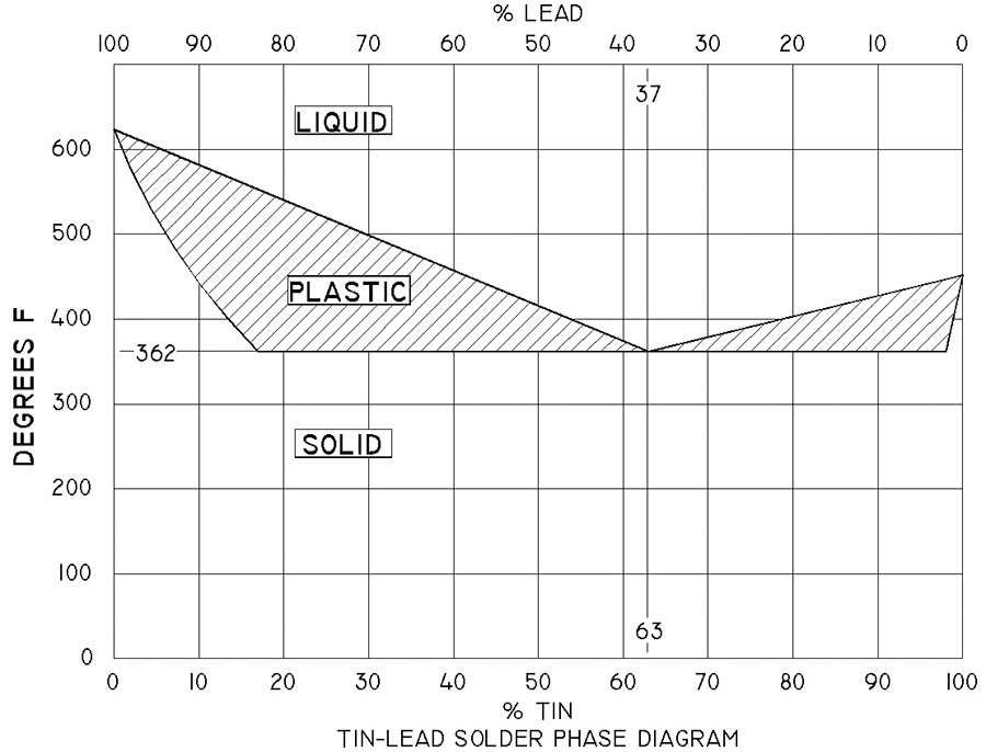
The adjacent phase diagram (Fig. 1) illustrates the behavior of tin-lead solder as a function of temperature and the ratio of tin to lead in the alloy. There are three features of 63/37 solder that are germane to our discussion. First, 63/37 solder has the lowest melting point of all other ratios. Second, 63/37 solder has no “plastic” range…the material transitions between liquid to solid phase over a very small range of temperatures. Finally, any departure from a eutectic mixture of metals will raise the melting temperature of the alloy.
A mixture of metals adjusted to minimum melting point is called a eutectic alloy. Eutectic tin-lead solder melts sooner (flows faster) than any other alloy, making for faster joining. This translates to less risk of heat damage to components. Further risk for a cold joint (visibly crystalline solder) is very low. The cold solder joint occurs when the joint is disturbed during transition through a plastic phase of cooling. Given that eutectic solder has no plastic range, the probability of a cold joint is very small. There are a great number of solders of varying alloys. For our purposes, the legacy tin-lead wire with electronic flux is well suited to our tasks.
Recall that solders are a solvent for base materials being joined; molecules of the base material literally dissolve into the molten solder. Imagine the effect of molecules of copper swimming out into the film of molten solder around a wire. Adding copper to the alloy raises the melting temperature. As the concentration of copper molecules in the melt rises, the liquid phase temperature for the new tin-lead-copper alloy will rise to a point that is greater than the temperature of the heat source…i.e. soldering iron.
Many instructions for soldering wires together call for tinning the bare wire with solder before making up the mechanics of the proposed joint. Once coated with solder, reheating the base copper and wiping will not remove the tinning…you can’t…the new tin-lead-copper alloy in the layer of tin will not become liquid at ordinary temperatures of your soldering tools and cannot be simply wiped off. The tinned surface is a new alloy at the surface of the underlying copper wire.
This leads to an understanding of the physical configuration of a soldered joint. When two wires are twisted together and soldered, the finished joint has (1) copper wire at the core, (2) a thin layer of tin-lead-copper at the wire-to-solder interface and (3) pure solder overlaying the total joint. Just as welding produces a solid mass of metal, soldering produces a solid mass of a mixture of metals configured in layers, from base metal as you move outward through the fusing amalgam, to an overall layer of pure solder.
The Right Mix
As a practical matter, 63/37 solder is a kind of specialty product and not nearly so common as 60/40. 60/40 is entirely satisfactory and probably easier to find. Finding solder with good flux is probably more important than holding out for the magic alloy. The best brands include, but are not limited to, names like Kester, Ersin, and Alpha Metals. Check eBay for good pricing on solder.
I would be remiss if I did not address the push for lead-free products. The aviation industry has been exempted from the lead-free mandates, due to poor mechanical properties of lead-free solders for surface mounted parts (joints fracture under vibration), combined with the propensity of high-tin solders to grow “tin whiskers” that cause shorts on the boards. The amount of lead that flies on airplanes soldered with 60/40 or 63/37 solder is environmentally insignificant.
Join Together
Let us consider one of the earliest applications of solder to the wire splicing arts. Figure 2 illustrates a Western Union or lineman’s splice. This simple treatment for bringing the ends of two wires together has been demonstrated to have no deleterious effects on the tensile strength of the wires. This splice was originally used to join long runs of wire between telegraph poles and no solder was used or needed. Tension on the span induced by the weight of the wire produced great pressure between the two wires. This pressure was sufficient to maintain practical conductivity in the open environment with no further treatment.
A freshly stripped pair of wires twisted together as shown will present a very low resistance joint. The problem is that our favorite wire is not solid telegraph wire, but stranded power and signal wiring. Further, our wires are not in tension. This joint assembly with no tensile forces is subject to the effects of moisture-laden oxidants. The joint’s electrical integrity will degrade with time.
The solution? How about solder? We know that eutectic solder with a bit of the right flux will form the strands of wire into a singular mass. In this instance, the solder contributes little or nothing to mechanical strength or even the electrical resistance of the joint. Solder has everything to do with protecting it from the environment…can anybody say “gas tight”? This forms a kind of cocoon impervious to intrusion of corrosive atmosphere.
Solder has qualities that go beyond simple encapsulation of a joint. While usually softer than the metals it joins, solder has structural properties suited to dual-purpose tasks: mechanical joining and electrical conduction.
For example, modern electronics use surface-mounted components where solder is the medium for both mechanical assembly and the conduct of electrons. How about wiring? Do we really need to do the two-handed, wrist-lock junction between two wires as described earlier, or can we simply overlap a short segment, say 3/8-inch or so of bare strands, and solder them? Sure. This makes for a much smoother joint, barely larger in diameter than the wires, and not nearly so lumpy when you cover the joint with heatshrink.
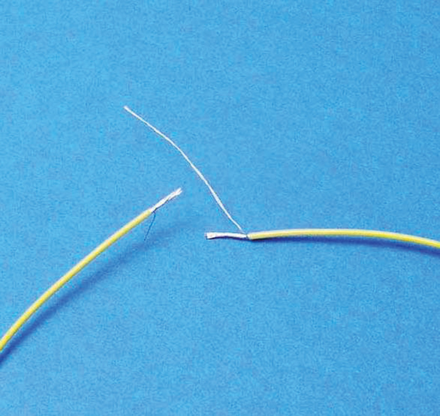
To lap-splice two wires, strip 3/8-inch insulation from one wire and about 1 1/2 inches from the other (Fig. 3). Then separate out one or two strands of the wire from the main bundle and trim the remaining bundle to 3/8-inch.
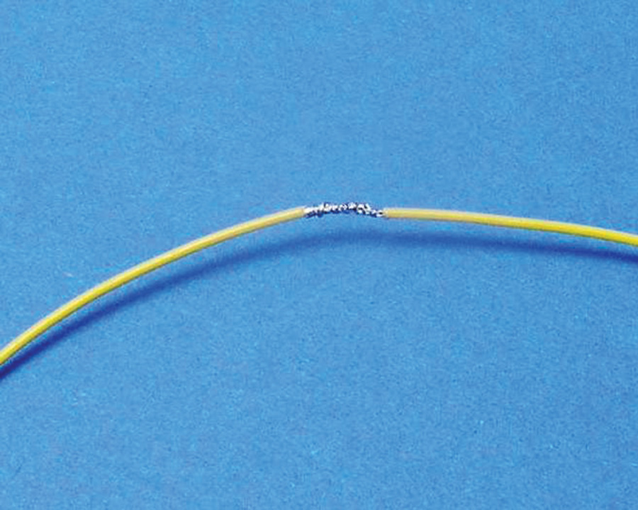
Overlap the ends and use the “flying strands” to fix them for soldering (Fig. 4).
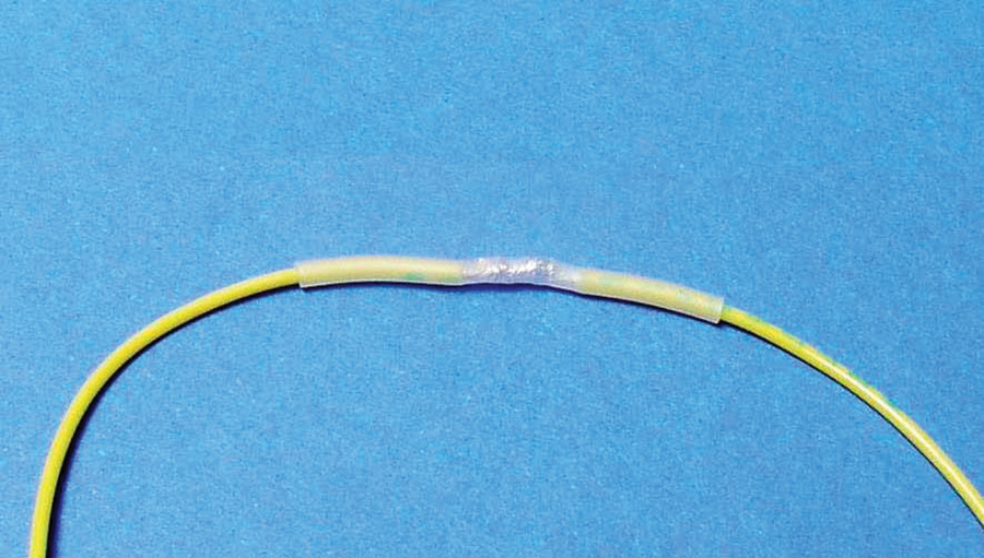
Solder with your favorite tin-lead and cover with heatshrink (Fig. 5).
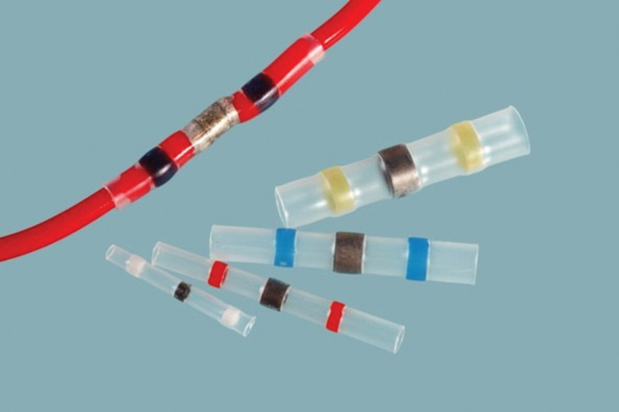
Some old timers would be astounded at this idea, but know that there is a military-approved product called a solder sleeve (Fig. 6). It’s a high-temperature heatshrink with a ring of fluxed solder around the mid-section. You can overlap stripped ends, slip a solder sleeve over it, apply heat and voila! You solder and insulate a lap-joint in one operation. Slick, but not cheap. The “poor boy’s solder-sleeve” I’ve just described is a useful alternative.
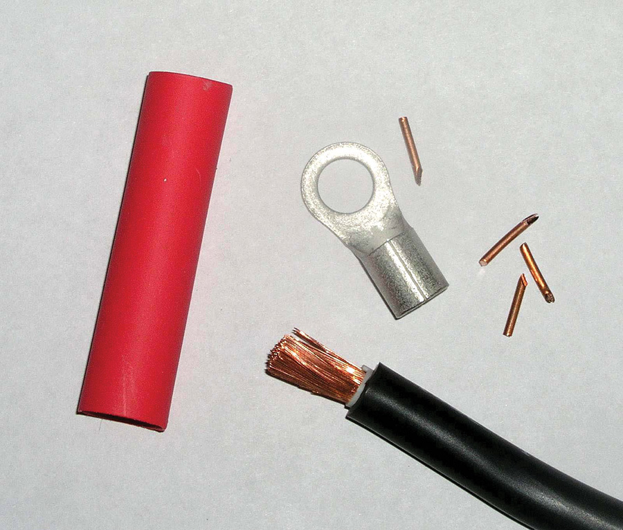
Solder offers an effective joining of big wires too. The materials needed to terminate the end of a 4AWG fat wire are shown in Fig. 7. In addition to a suitable terminal, you need some cylindrical copper wedges fabricated from 14AWG house wire and some adhesive-wall heatshrink.
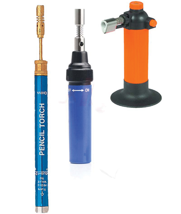
You will also need a small butane torch. Figure 8 shows a few examples of refillable butane torches. The center torch is one of my favorites. You can find it on eBay for under $10 delivered to your door. It comes with torch and solder tips (handy for doing a solder job in the hangar where AC main power is not available).
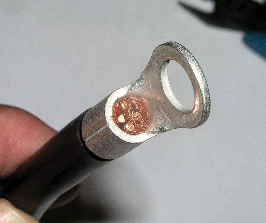
Slip the terminal over the prepared cable and stuff copper wedges into the ends of the cable until the terminal is snug on the wire (Fig. 9).
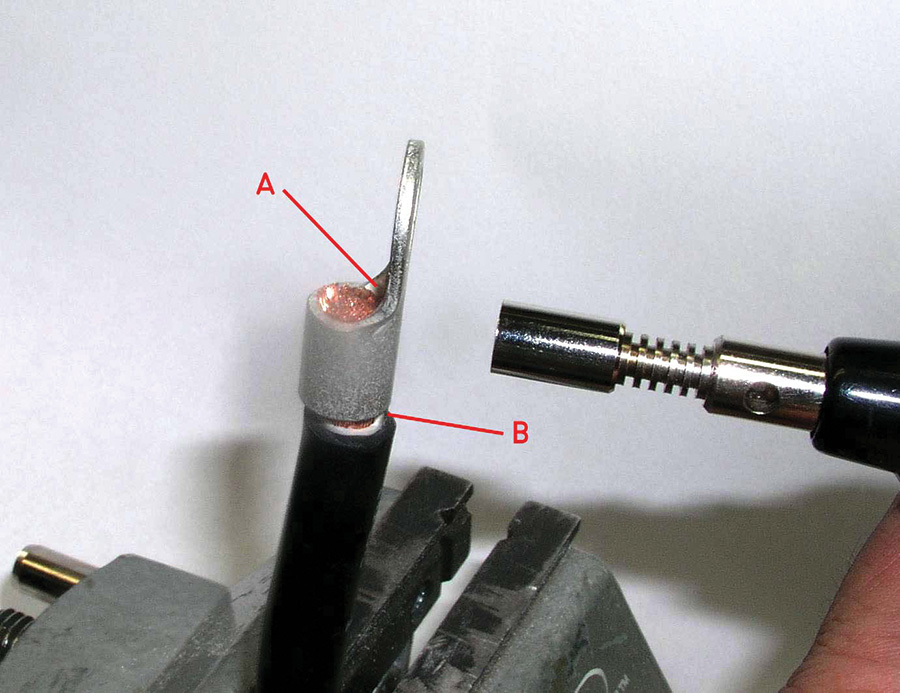
Set the torch flame for about a half-inch blue cone. Apply heat to the back side of the terminal (Fig. 10) and test the temperature by touching solder to the corner of the terminal flag and end of the wire (A). When solder begins to flow to the terminal, start feeding the solder into adjacent strands.
Walk the heat around the terminal barrel at the upper end away from the wire’s insulation while wetting the strands of wire with solder. It will take quite a bit of solder to fill the joint. Stop feeding solder when the exposed end-strands are fully wetted and you see the first trace of solder at the wire entry end of the terminal (Fig. 10-B).
I suggest that you practice this technique a bit before you commit to work on the airplane. If you don’t like the first attempt, you can salvage the terminal by re-heating it and pulling it off the wire. Heat further and fling the molten solder off the terminal. Careful, don’t splash your foot! Strip a new end on your practice wire and try again.
Let it cool and cover with short piece of 1/2-inch, dual wall heatshrink for a nice finish and to and provide vibration support for the stranding (Fig. 11). Looks pretty professional, no?
For more detailed studies on the art and science of solder joints, I recommend this NASA Technical document that will expand on the ideas offered in this article.
Next month, the third article in this series will debunk a few popular myths about soldered joints. We’ll also explore the mechanical aspects of terminating wires that are shared by both the crimped and soldered joint.

