One day last summer, seconds after rolling from the hold short line to depart Las Vegas’ Henderson Airport, a freak wind gust caught David DiGiuseppe’s Glasair 1 TD. In that instant, the plane was lifted up, twirled around and slammed to the ground. A nanosecond later, David knew this airplane isn’t going anywhere today.
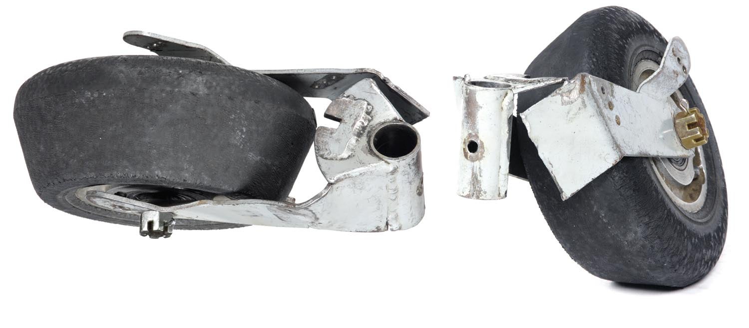
As the Glasair limped back to the parking area, David knew from the sideways tracking and grinding noise that there had to be some serious damage. At first glance the tailwheel was obviously messed up. Amazingly, a detailed inspection of the main structure revealed nothing: no cracks or telltale signs of delaminating. The mains and engine mount looked good. All that was messed up was the tailwheel and fork weldment. One side was sheared from the weld and the other was twisted so badly that it dragged off half the tire tread during the taxi back from the runway.
I was wrapping up last month’s column when Kevin King called to ask if I knew a welder who might be able to help David remake his tailwheel assembly. One thing led to another and I was looking at my next project for the Home Shop Machinist!
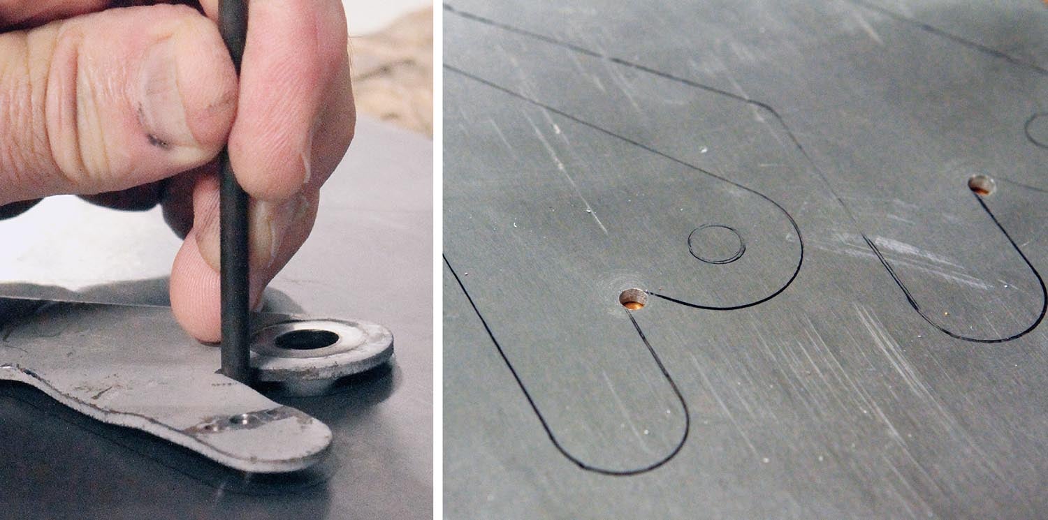
 David is not the builder of his Glasair, but he has the plans. He discovered the tailwheel fork was scratch-built based on drawings (as opposed to a factory- or vendor-supplied tailwheel, such as Matco). But the drawings provided only general guidance for dimensions and materials. When we met to discuss the project, I concluded that we didn’t really need a detailed drawing because we had the original which, even in its mangled state, was intact enough to “reverse engineer” (see sidebar below).
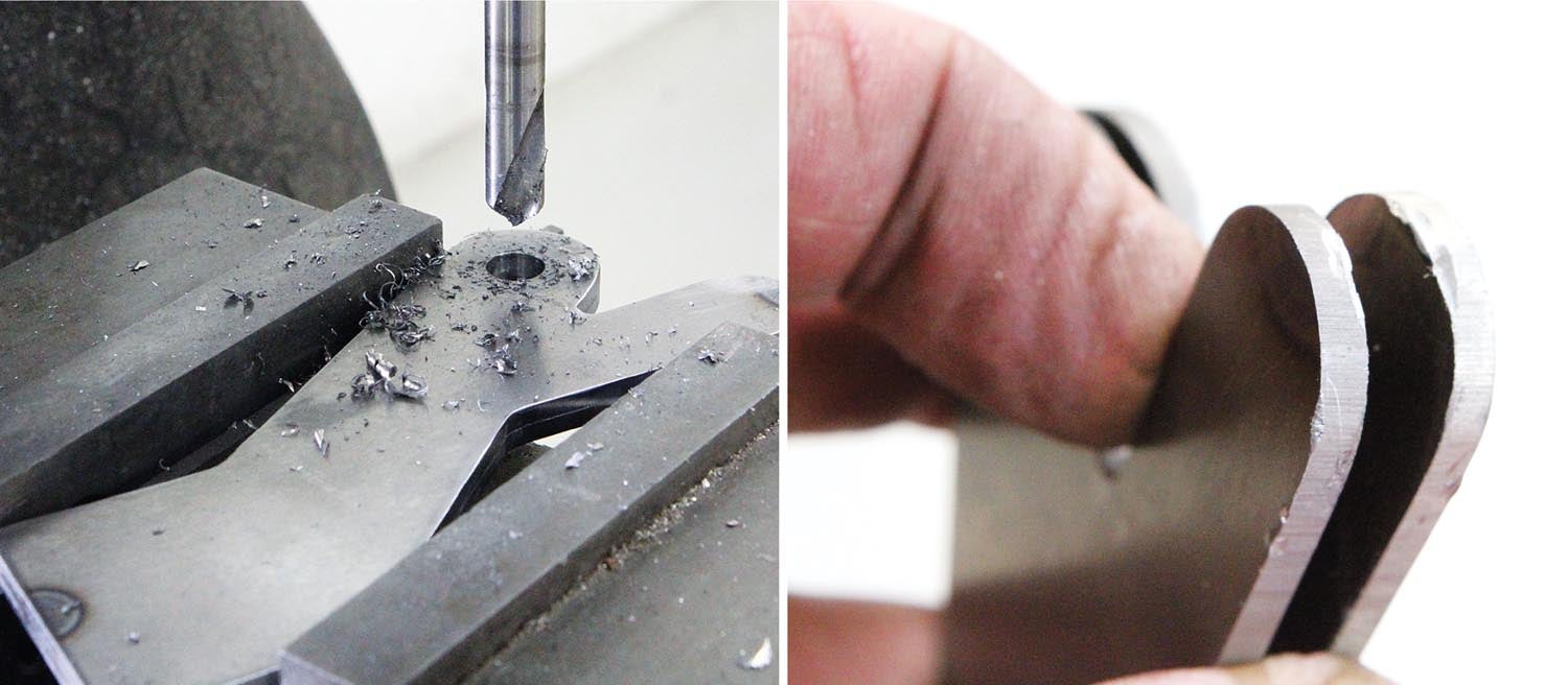
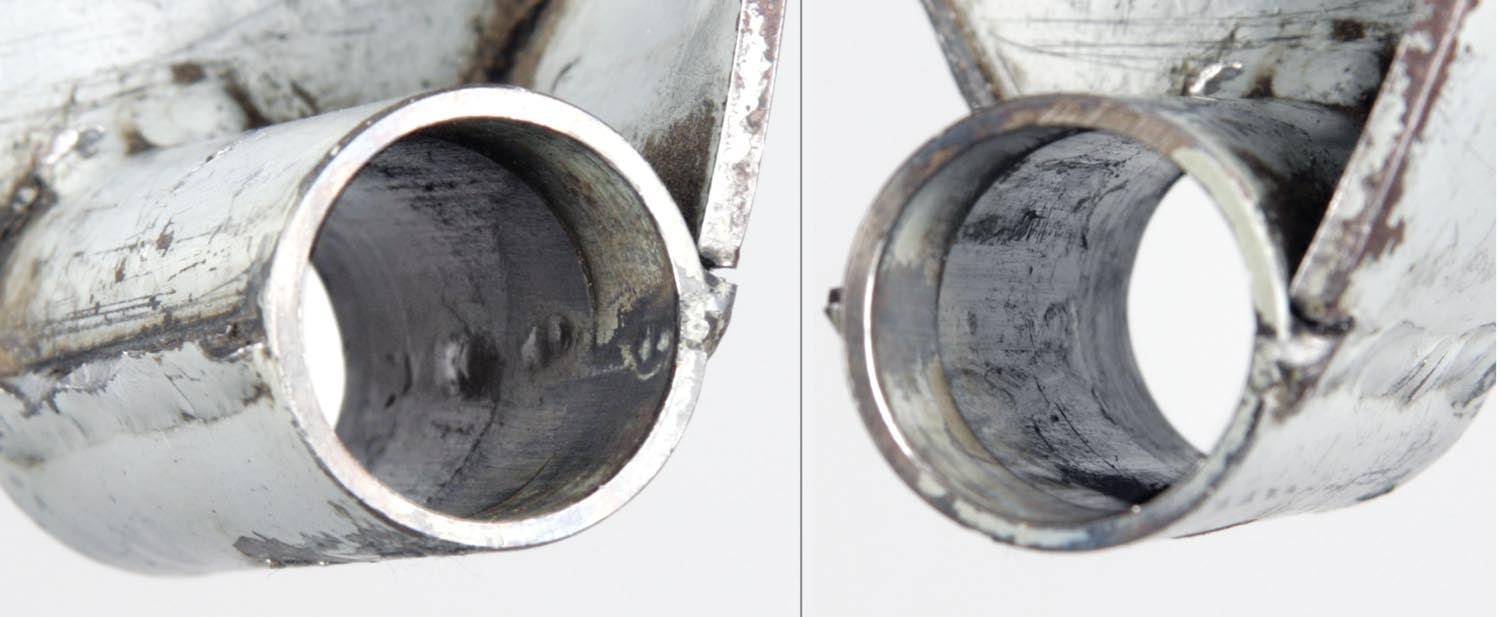
The tailwheel, before the incident, worked perfectly, so there was no need to make any changes to the design. One thing I did note about the original was the way the weld failed: The leg that separated didn’t have good weld penetration. The telltale signs were how the weld tore away along the seam—both along the steering tube and along the upper gusset—and how, on the inside of the steering tube, you could see how the weld showed little, if any, penetration.
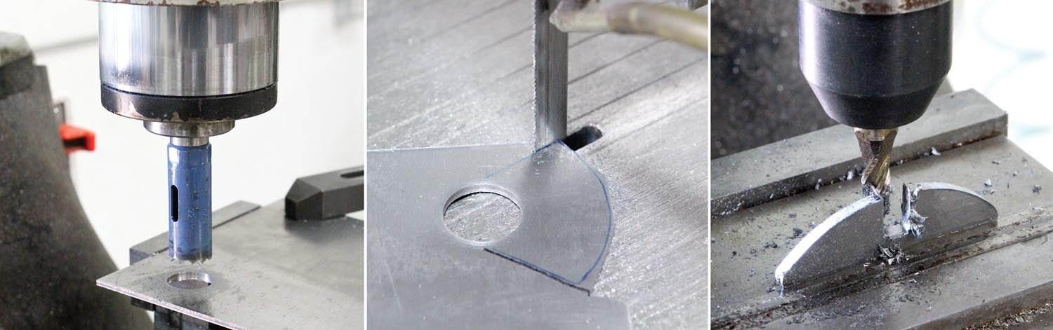
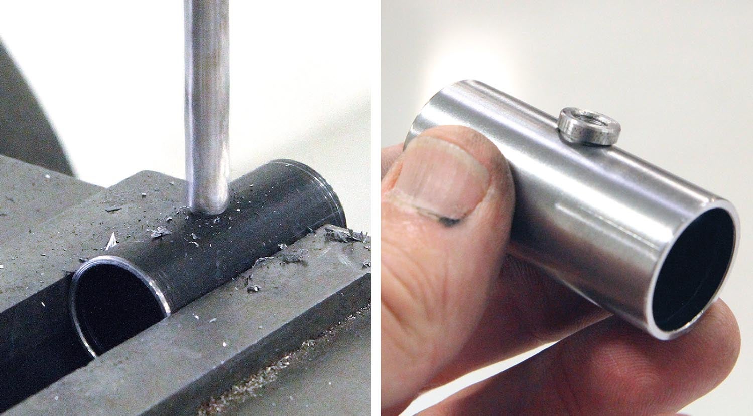
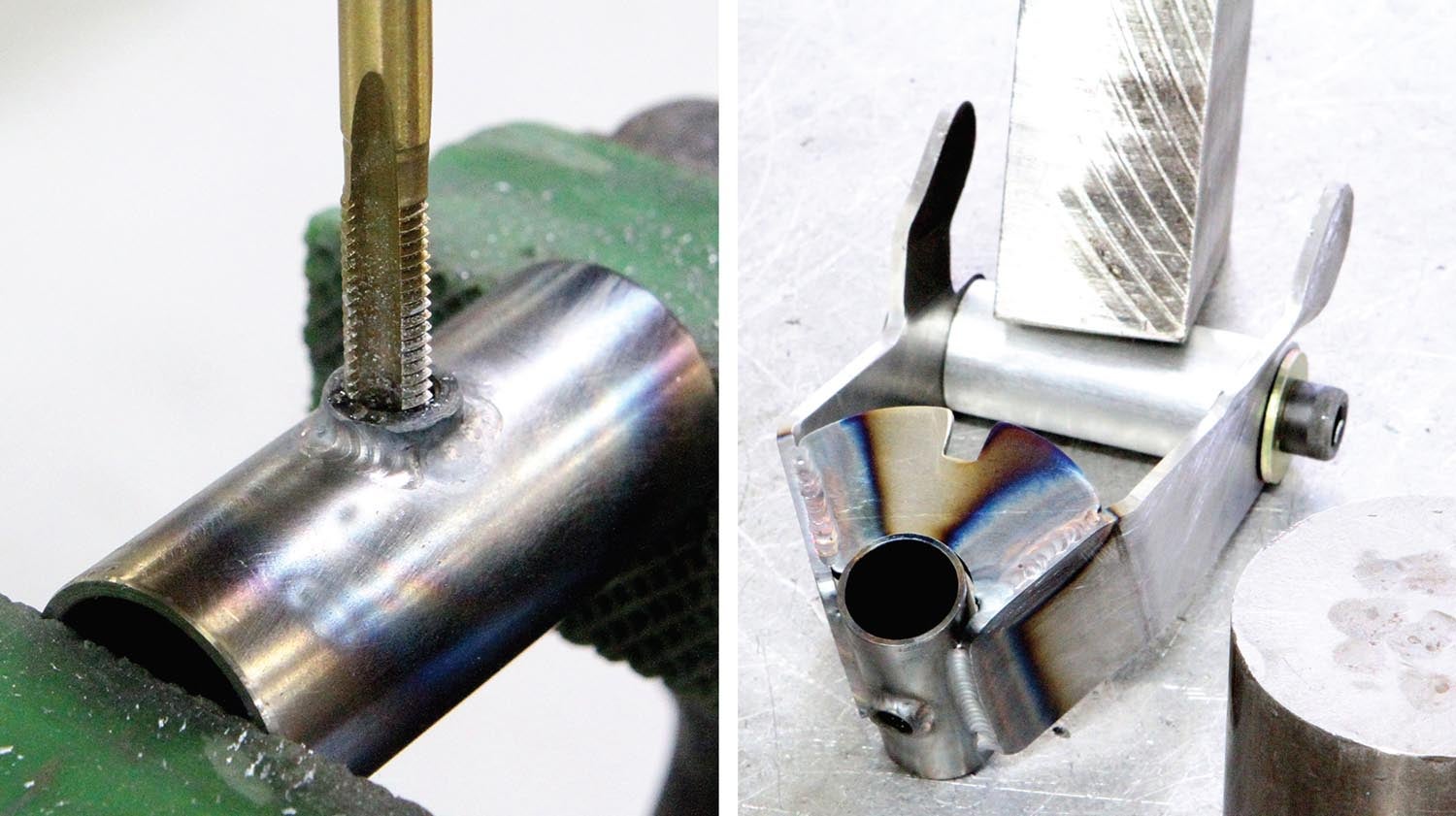

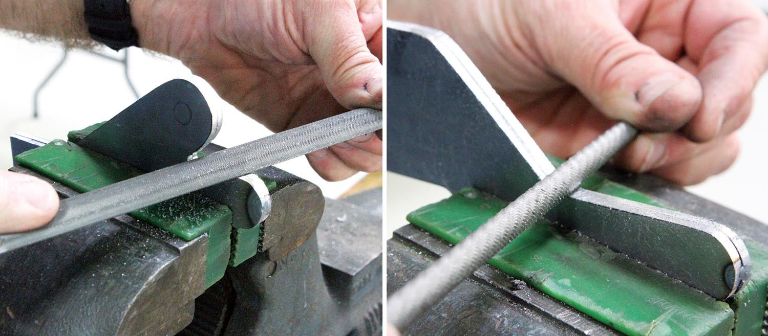
With that, my task was clear: Make David a new tailwheel weldment, as close to the original as possible but with improved welding. I implemented one change to the design, which was the addition of a threaded bung to better accommodate the grease fitting that was threaded into the steering tube. The original had the fitting threaded directly into the thin-wall tubing, which meant it was barely able to be tightened beyond finger tight. Any tighter and it would have stripped out.


Did the tire get that worn just from taxiing back to the hanger?
I was wondering the same thing !
Yes. The damage to the tire/wheel happened during the taxi back to the ramp. The tailwheel was more or less dragged on its side, which ground of the tread like an eraser on sandpaper.
Update from David after more than a year in use: “It’s still working good. No issues.”
patents stifle innovation, and these days mostly only benefit large corporations not the little guys. As an engineer with over 20 patents as of now and counting, I don’t believe patents should apply to individual noncommercial use (regardless of the law).
Comments are closed.