Every aircraft has tie-down points. Most of us never give them a second thought until a catastrophe strikes—like the big storm that threatened early bird arrivals at Oshkosh this year. High winds in town knocked out power and downed several trees. But at the airshow grounds, only one aircraft got upended (an EAA-owned biplane that was on display near the museum). Among the estimated 1500 visiting airplanes, there were only a few reports of minor damage. Credit the storm forecasters, aircraft owners, volunteer crews and makers of tie-downs for a job well done! And don’t forget the structural engineers who figured out where and how those hold-down points go on your airplane.
Steve Cogswell didn’t make it to Oshkosh this year. He’s still in the process of flying off the 40-hour Phase I test requirement on his RV-8 (see “A Tale of Two RVs,” June 2022). Although the airplane is “done” as far the FAA and airworthiness inspections are concerned, Steve, like every builder, has been busy addressing issues (squawks) that have cropped up during Phase I. In no particular order, a crackly radio, repositioning oil cooler lines and adding doodads to prevent the back of the canopy from wobbling and scuffing the paint.
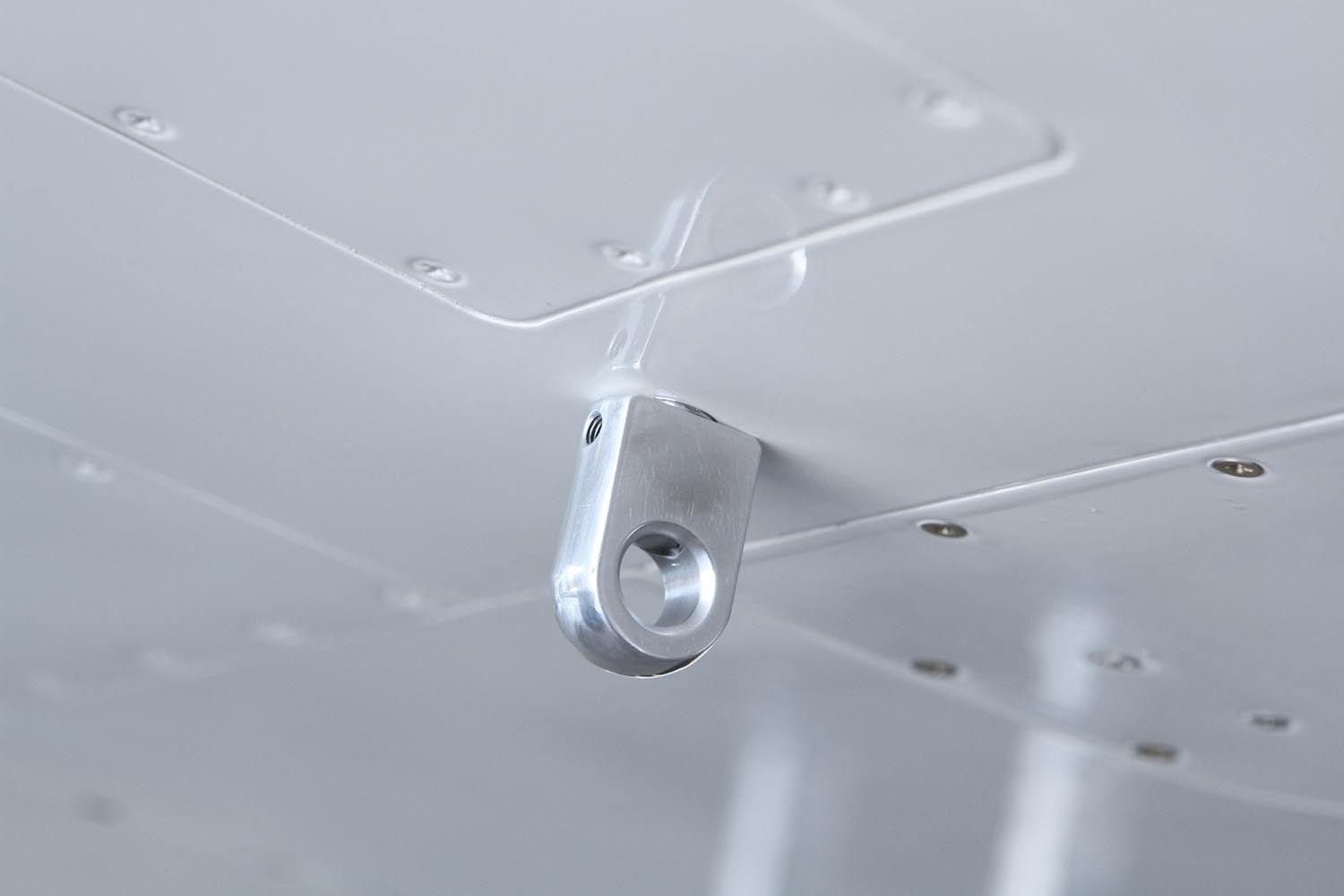
In between squawks, Steve whipped up a set of cool aluminum eyebolts for the wing tie-down points. The factory tie-down holds are steel 3/8-16 eyebolts that, according to Steve, “look like parts from the hardware store, which they are.”
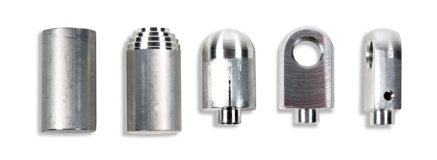
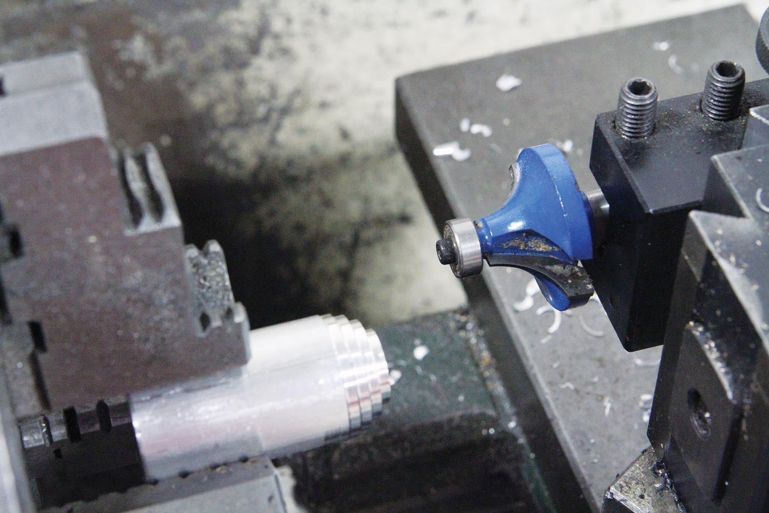
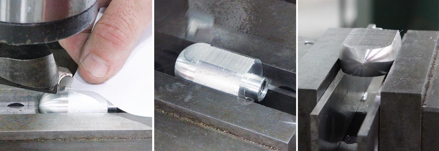
Steve’s tie-down eyebolts are machined from 1-inch diameter 6061 bar stock. The cool design feature is the turned ball end on the round stock that, after the sides are milled, lends a sense of “factory-made” to the part. There are several ways to go about making a ball end. One way is with a spherical turning attachment (see “Sphere Turning,” December 2016) that can be adjusted to turn a perfect sphere of any size (up to the capacity of the tool), but they are a bit pricey for one-off jobs. Another way is to use a contour bit, which is a lathe tool specifically ground to make a radius. You can buy a radius tool from any of the machine-tool supply houses, but at $50 it also may be a bit high-priced for making one or two parts. Yet another way is to use a common woodworking router bit. Yes, you read that right—a woodworking router bit. In this case a half-inch radius round-over bit. Amazon price: $14.
Instead of the obvious, which would be spinning the bit with a milling machine or router, the bit is stationary with only one edge being presented—just like a forming tool. Since router bits have a round shank, it helps to have a tool holder with a V-notch groove to align and hold the cutting edge in place, but you could also use a boring-bar holder.
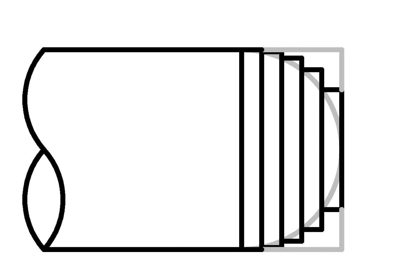
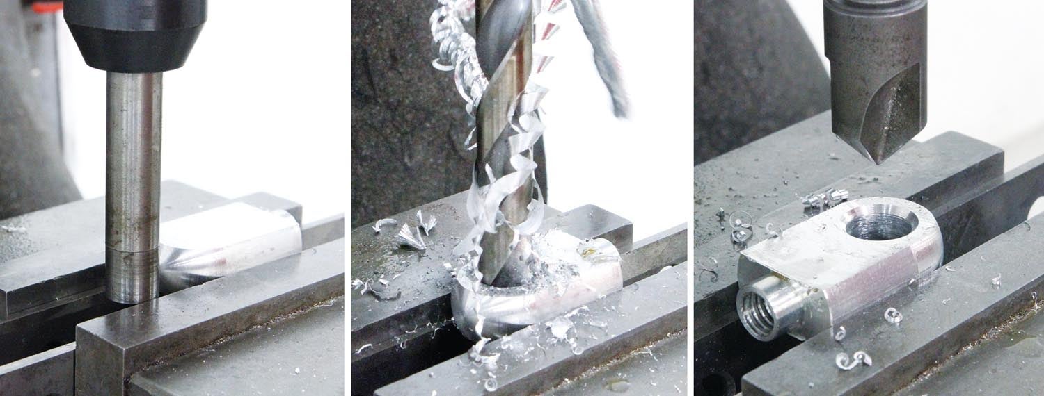
To speed up the machining, I sketched out a step pattern to “rough out” the end. Roughing out, or rough cutting, is a common shop practice done to remove waste material in bulk before forming or finishing cuts. The idea is to speed up the machining process and also reduce the workload on any special “finishing” tools. This step was probably not necessary for this job because relatively little material was removed, but in general, rough cutting is a good practice to incorporate into your machining procedures.
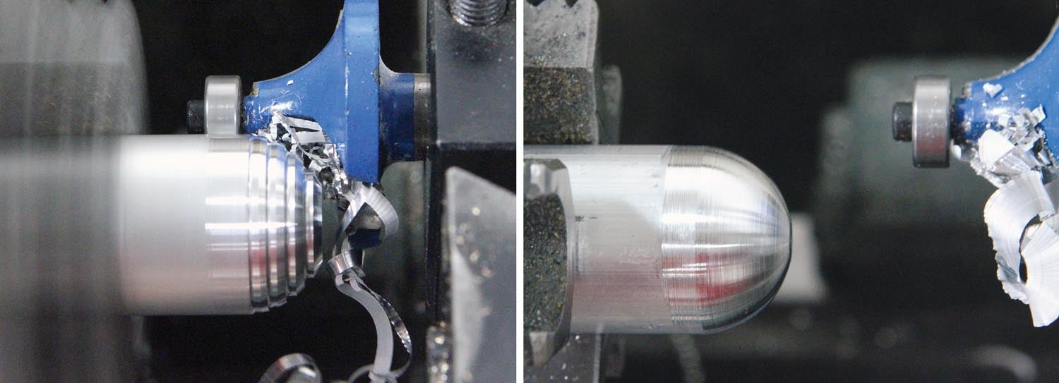
The key to getting a perfectly round end with a router bit is to set the cutter face as flat as possible and have the tip of the cutter (the edge of the big end) as on-center as possible.
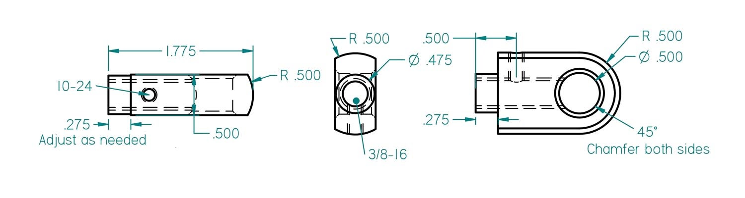
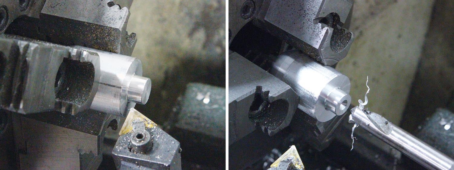
Steve’s eyebolt design is specific to his RV-8. But he also mentioned that the 0.275-inch shoulder dimension could vary from one airplane to the next. The shoulder is there to provide stand-off distance, which prevents the corners of the eye from digging into the wing and damaging the paint.
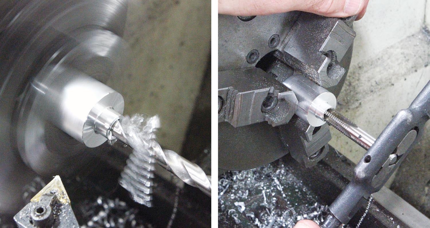
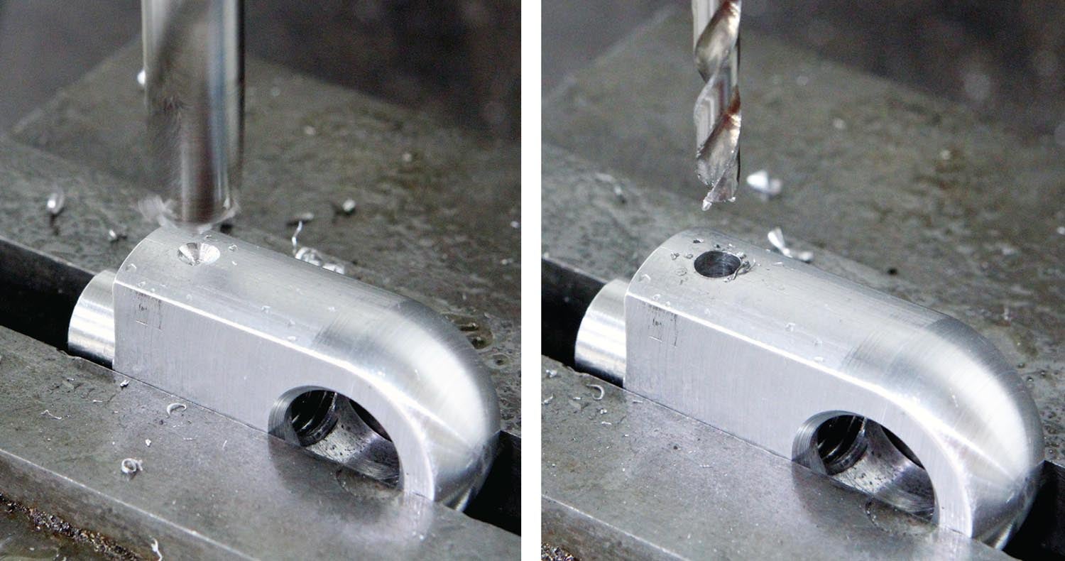
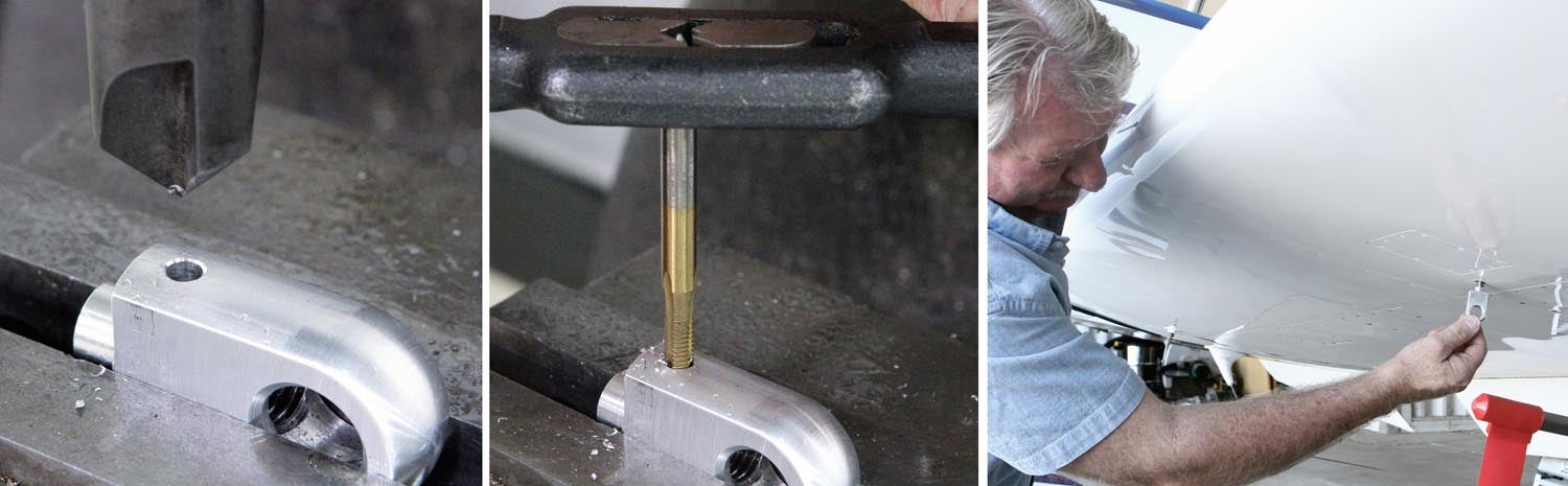
Also note the inclusion of a set screw. This allows you to set the eye in line with the wind if you decide to leave them on during flight. Steve prefers not to have the additional drag and plans on storing them in his flight bag when not being used.
That’s it for now; time to get back in the shop and make some chips!


