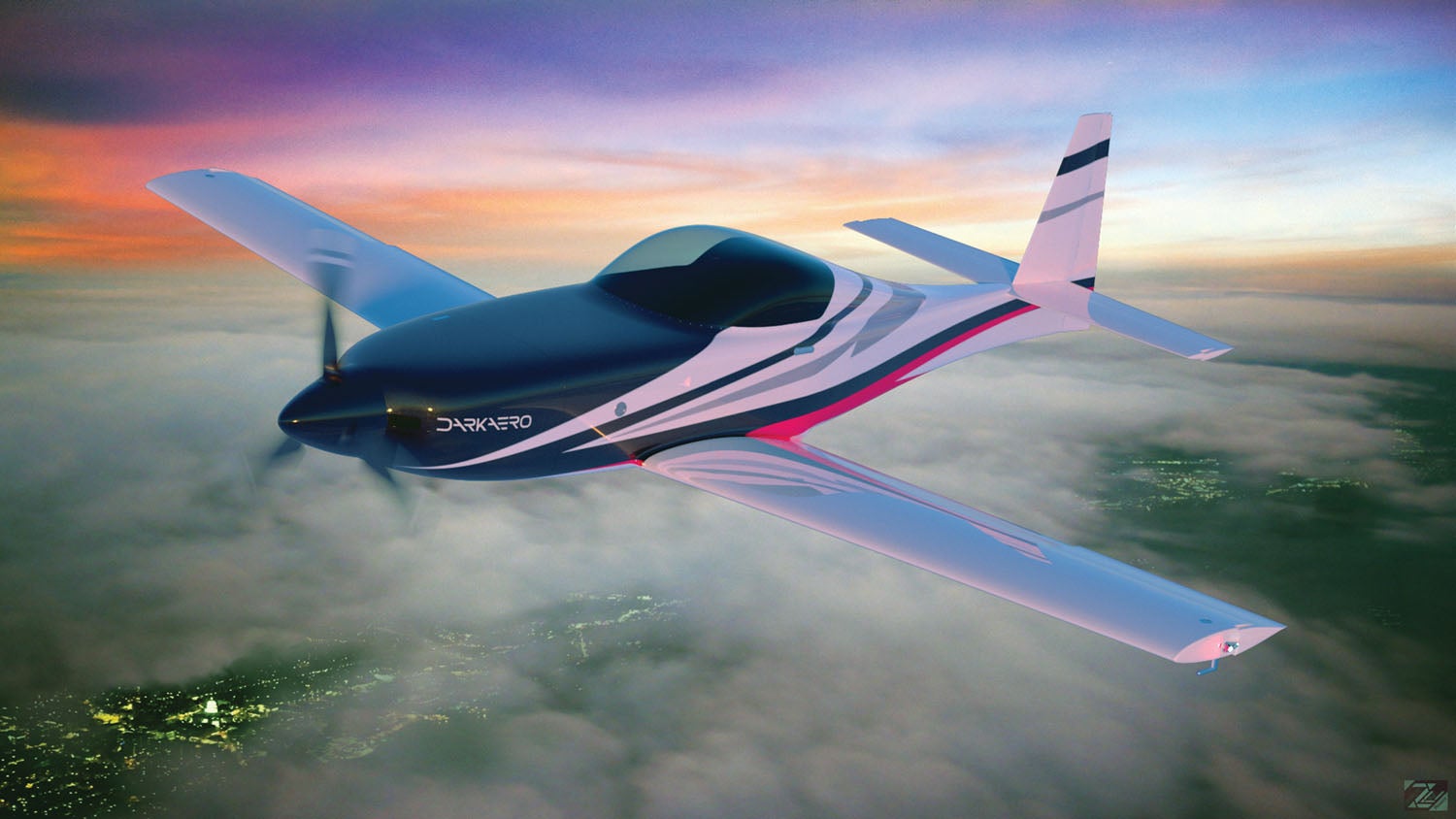
In Part 1 of the DarkAero story, we gave a general overview of the company and the Karl brothers’ goals for the DarkAero 1. In Part 2, we’ll take a closer look at manufacturing techniques and other aspects of the kit that make this aircraft unique. Our interview covered a wide range of topics, and all three brothers participated in the conversation.
KP: There are a lot of kits out there. How is the DarkAero 1 different from a typical composite homebuilt?
Keegan: We want the build process to be enjoyable and rewarding. Composites (particularly carbon fiber) are fun to look at, hold and work with. But that generally isn’t the case when building a composite aircraft. It can end up turning into a sculpting project with many hours dedicated to fill, sand, fill, sand, fill, sand…
Two big things we’re doing differently are eliminating that bodywork and the messy wet layups. We don’t see these tasks as rewarding or a good use of a builder’s time. Our philosophy is, if we design well on our end, those steps should be removed on the builder’s end. That’s why we put a lot of effort into making precise molds and creating premolded components that the builder simply needs to prep and bond together. Composites work can be intimidating; I think that’s why a lot of people shy away from composite Experimental aircraft and turn toward more traditional materials like aluminum. We want to change that.
The other big thing we are doing is integrating the instructions with the Onshape CAD files. This allows the builder to see the CAD for various portions of the build on their own computer. They can see the assemblies from any angle, hide portions, zoom in, zoom out and see exploded views.
KP: What kind of testing or research did you do before starting the project?
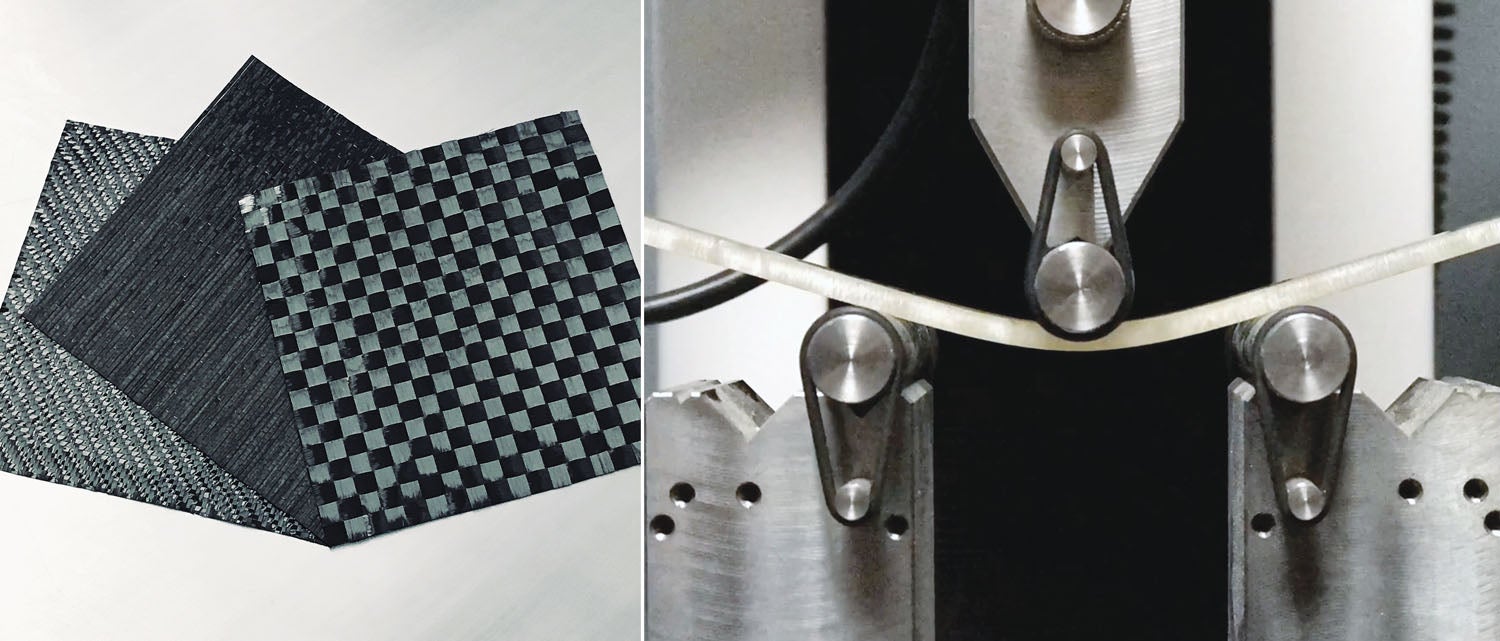
Ryley: We started the project with extensive experimenting and testing. We played around with many different epoxy resins and adhesives as well as different composite cloth weaves, cloth weights and fiber types. We explored different core materials like aluminum and aramid honeycomb, foam, balsa and infusible cores. We also experimented with different processes like 3D printing, wet layup, vacuum bagging, infusion and prepreg. We made lots of test samples, weighed them, broke them and documented everything. The lessons we learned at this stage laid the foundation for what materials and processes we wanted to use and also sparked new ideas for assembly procedures and structures in the DarkAero 1.
KP: In addition to the preliminary testing, I understand that working on Ryley’s Cozy also influenced your approach to the DarkAero 1.
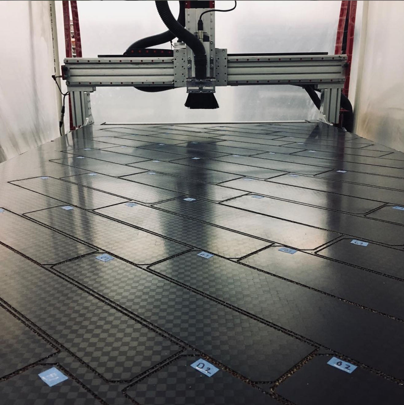
Keegan: Ryley’s experience building the Cozy set a good stage for things we wanted to experiment with in manufacturing the DarkAero 1. Composites work is still a very labor-intensive process; we all knew this from working on the Cozy. Hand laying cloth in a mold and applying epoxy takes time, and anything you can do to either eliminate steps or eliminate parts is a good strategic move. Early time studies drove us down the path of our Hollow Grid technology. We wanted to eliminate the labor intensity of making many composite ribs, and that’s when we started experimenting with honeycomb panels. With the panel approach you can make a single panel but get many parts from it using a CNC router. This approach improves quality, repeatability and reduces manual labor.
KP: That’s an interesting approach to kit building. It also looks like the panel method allows you to adopt a “Tab A into Slot B” assembly approach.
Keegan: We don’t require the builder to purchase or build any special tooling or jigging to finish their DarkAero 1, and we do a lot of slot and tabbing of the fuselage bulkhead panels. This allows us to build up the internal structure of the fuselage with minimal tooling.
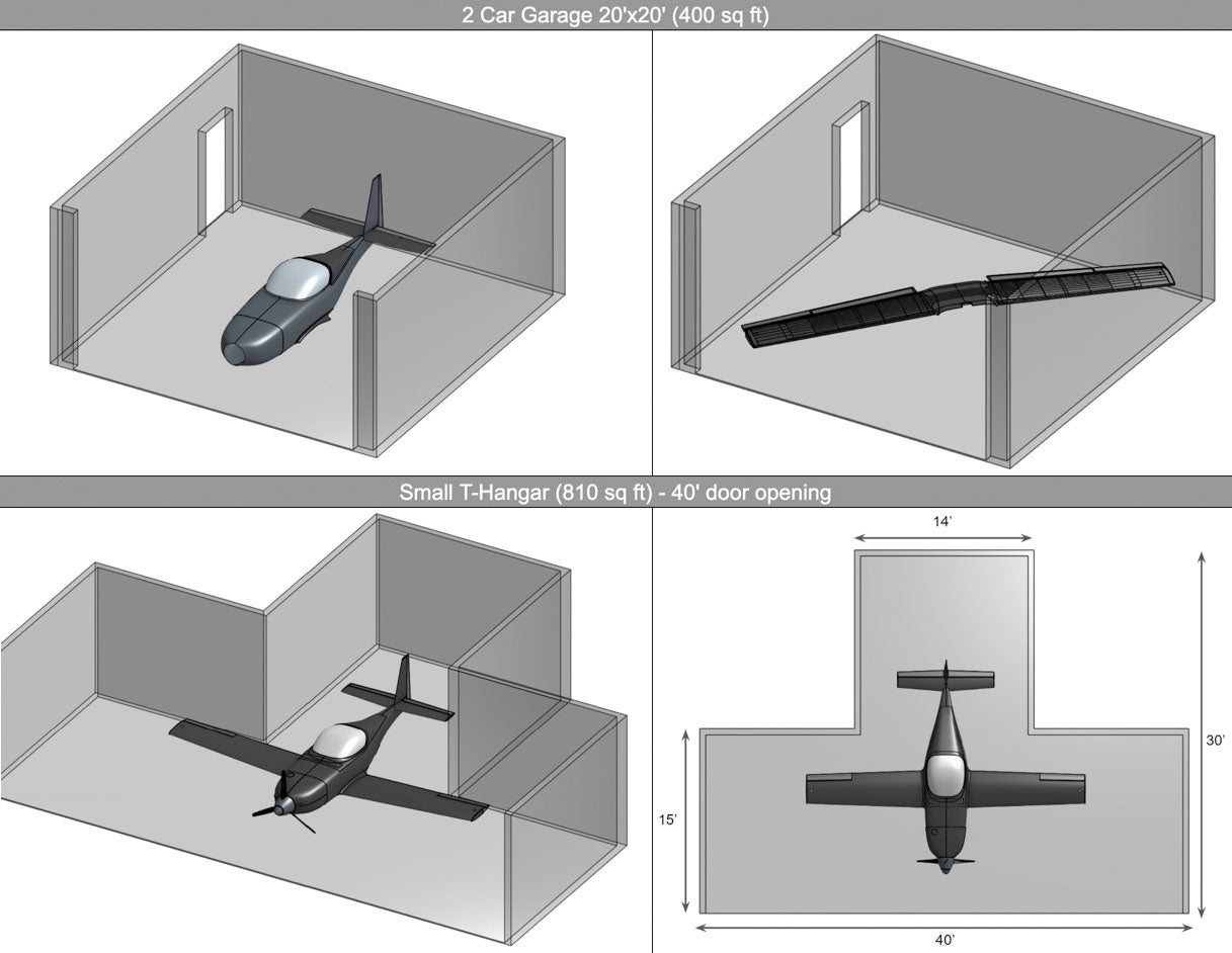
Ryley: We designed the kit with the first-time builder in mind, and quickbuild is the standard option. You can build it in your garage—no need to visit the factory.
KP: How are you ensuring quality control? That’s usually a bigger factor in composites than metal aircraft.
Keegan: Every composite part and every panel we create follows a procedure. All the information and variables that go into these processes are documented to ensure we are getting consistent results. We only use aerospace grade materials, and we record the data for that material for every final part so everything is traceable. For example, all our epoxy contains a serial number, documented for each infused part that uses it.
Ryley: In addition, all our composite structures get post cured in a computer-controlled oven to ensure full cure of the epoxy for full mechanical properties. There are temperature sensors throughout the oven that record a detailed data file documenting the specific temperatures/durations at different locations. We worked with the Polymer Engineering Center at the University of Wisconsin-Madison to validate the details of our cure cycles.
KP: Although composites are touted for having superior strength, composite aircraft often end up being just as heavy, if not heavier, than aluminum airplanes. How much attention do you pay to weight?
Ryley: Weight reduction is a pretty big piece of the puzzle in achieving the performance we are aiming for. Keeping things light is a virtuous circle: A lighter aircraft means you can have a smaller wing, thus less drag. Less drag means more performance or a smaller, lighter engine. Weight reduction is probably the most important area of the design; we put a lot of effort into it because so much hinges on weight.
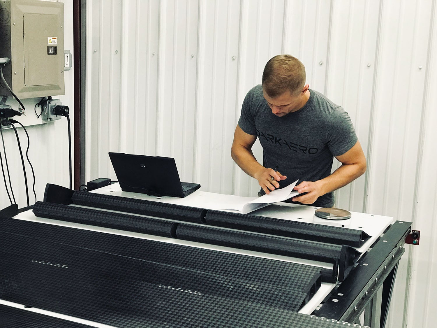
We got really obsessed with weighing everything early in the project because we were trying to understand the fiber-to-resin ratios in our composite parts. This bled into other aspects of the build, and we ended up weighing everything, right down to nuts, bolts and washers, which really add up over an entire aircraft.

KP: How did this concern for weight translate into the design of the aircraft itself?
Keegan: Before we left our jobs to pursue DarkAero full time, most of our efforts were focused on analysis and testing. As Ryley mentioned, we conducted a lot of coupon sample testing of our composite structures and then worked our way up to smaller assemblies. From there we went on to build up entire assemblies and tested those as well. The first full assembly was the horizontal stabilizer. Following this, we worked up to large structures like the wing. The approach we took to analysis and testing is very much in line with FAA-AC-20-107B, which you can download from our website.
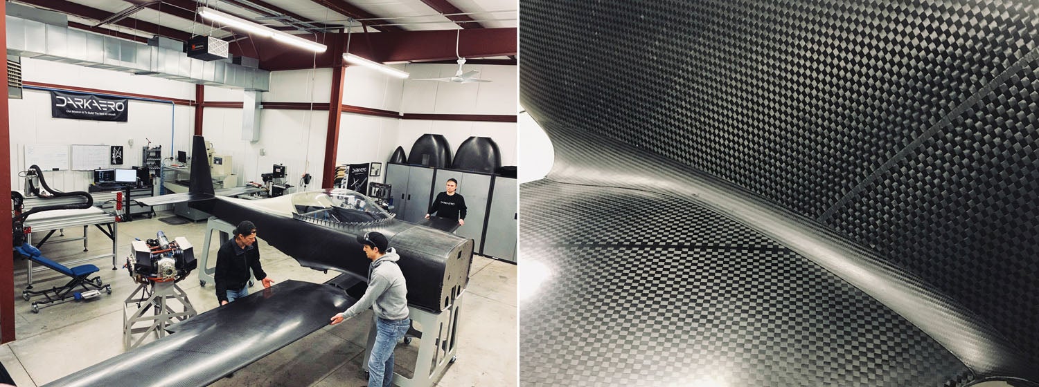
Materials are picked out based on function in particular and mission of the aircraft in general. Carbon fiber is both strong and lightweight, which is why we picked it for the primary airframe material. Beyond that, we also selected materials based on their manufacturability. For example, Kevlar is strong, light and has good toughness. However, it is very difficult to machine and challenging to cut, so we don’t use much Kevlar.
KP: The DarkAero 1 is a carbon airframe, but we see Keegan machining a lot of metal parts, which appear in your videos.
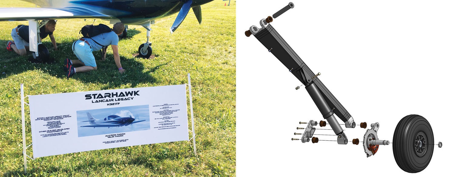
Keegan: That’s right. For the prototype, we machined the engine mount, nose gear and main gear. These components are a combination of 6061-T6 and 7075-T6 aluminum, which all gets machined on our CNC mill. We also have several CNC-machined carbon fiber components that include hinge brackets, control system bell cranks and hard mount points. These are all machined on our CNC router.
We try to keep as many manufacturing processes as possible under one roof. There is so much we learn from making our own parts that provides us valuable feedback for improved manufacturability and/or functionality. Between our CNC mill and router, we can really tighten that feedback loop between concept and first test article. One-off machined parts can also get really spendy if we were to pay someone else to make them for us, so keeping prototype parts in house is a win-win for us.
KP: To continue on the theme of CNC machining: You mentioned in one of your videos that you switched from SOLIDWORKS to Onshape as your CAD program for this project. What led to that decision?
Keegan: We all had backgrounds using computer-aided design tools from our experiences as undergrads and in prior jobs. There are many CAD programs to pick from like Creo, SOLIDWORKS, Rhino, Siemens NX, etc. We were most familiar with SOLIDWORKS and initially used that for designing the prototype. This required us to build up a CAD computer workstation that had high-end components for processing and graphics. We had to take turns on that one computer doing design work for the aircraft, which wasn’t ideal.
We could have purchased a few more computers and copies of SOLIDWORKS, but that would have been quite expensive. [Note to readers: EAA offers members free access to SOLIDWORKS, but it is an educational copy that prohibits use for commercial purposes like the DarkAero 1. The price for a commercial license varies depending on the bells and whistles you opt for, but for an aerospace project it could be well north of $10,000. You can see why the EAA deal is pretty amazing!]
Additionally, we didn’t yet have a good system set up for linking together all the design files. Around that time, we heard about Onshape. It’s a fully cloud-based CAD package that doesn’t require any downloads or fancy computer hardware. On top of that, it was founded by the team that made SOLIDWORKS, and they had a built-in feature for sharing part files and getting everything to link together. We tested it out and immediately saw its value. We made a full switch and haven’t looked back. What is really slick about it too is that Ryley and River prefer to use Apple computers whereas I prefer a PC. Onshape doesn’t care either way—all you need is an internet connection.
KP: Let’s move on to some unique parts of the DarkAero 1. In fact, let’s go to the most obvious one first—you’re using a split rudder, which is rather unusual.
Ryley: Our integrated split rudder/speed brake is similar in concept to what is seen on the Space Shuttle where two rudders are attached to the vertical stabilizer and can actuate independently. They can deflect left or right to provide yaw control, or they can both deflect outward simultaneously to function as a speed brake. Actuation of the two rudders on the DarkAero 1 is identical in operation to what has been proven on Rutan-style canard aircraft, which also have two independent rudders.
There are a few advantages to a combined rudder/speed brake: It eliminates an independent speed brake system, simplifies the build, reduces weight and reduces cost. The disadvantage is that it is a little bit unconventional, so we will have to test it out. If we don’t like it, it shouldn’t be too difficult to revert to a conventional rudder. We are really excited to test it and share what we learn!
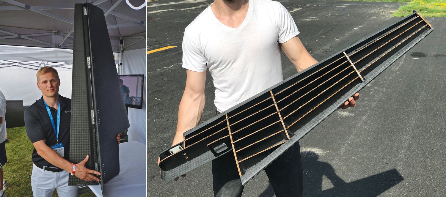
KP: Let’s talk about the next unusual feature of the airplane—the Hollow Grid system.
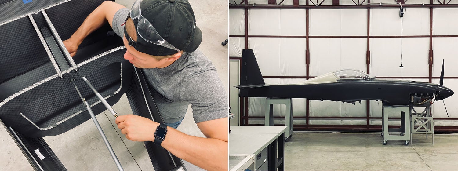
Ryley: Another noteworthy aspect of the DarkAero 1 is the approach we took to building the wings, horizontal stabilizer and vertical stabilizer. Rather than using a central spar to carry aerodynamic loads, we used a stressed skin with an internal grid of honeycomb ribs and shear webs to support the skins against buckling. The internal structure is CNC cut from bulk honeycomb panels and preassembled with jigs before being bonded to the structural skins. We call this design and approach Hollow Grid, and we picked this method because it presented some manufacturing advantages as well as producing light, structurally efficient flying surfaces. Another advantage is that it yields a wing that is hollow and can be used to store fuel as a wet wing.
KP: While preparing this story, you mentioned that the horizontal stabilizer had been built twice. What’s the story there?
Ryley: I had some experience with mold design and construction from previous industry work, and we had several ideas for tooling that we wanted to explore. We started building molds for the horizontal stabilizer and tried a different form of plug-and-mold construction on each molded component.
We learned a lot doing this and by the time we finished, we had a bunch of plugs and molds we didn’t like and a horizontal stabilizer that we knew we could build better, so we started over. We took the best of what we learned building the first HS and carried that forward into a completely new set of plugs and molds. Those new methods were much better and ultimately what we used for the molds in the rest of the airframe.
KP: I understand you also built several canopies?
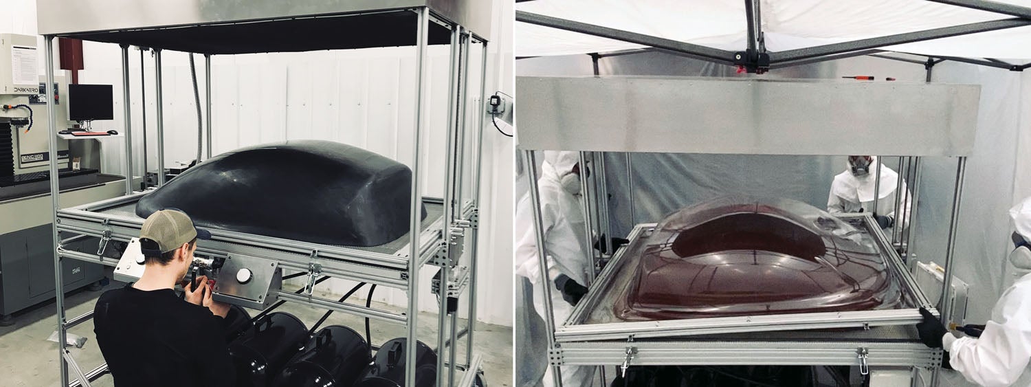
River: Given our eye toward bringing the bulk of manufacturing in-house, we felt the canopy was no different. We had successfully built a 24-foot cure oven, so we figured the canopy would be a similar challenge. We were able to build a canopy forming machine or “thermoformer,” and it actually works well in principle.
We were able to form a couple of canopies that look good at a distance, but up close they are not something we’d feel comfortable looking through for several hours in flight. Solving the optical clarity quality issue turned out to be a massive challenge, and for now we have tabled that challenge. For the time being we are opting to have the canopies manufactured by Airplane Plastics in Dayton, Ohio, to allow us to focus on the remaining challenges of getting the plane flying and into production sooner.
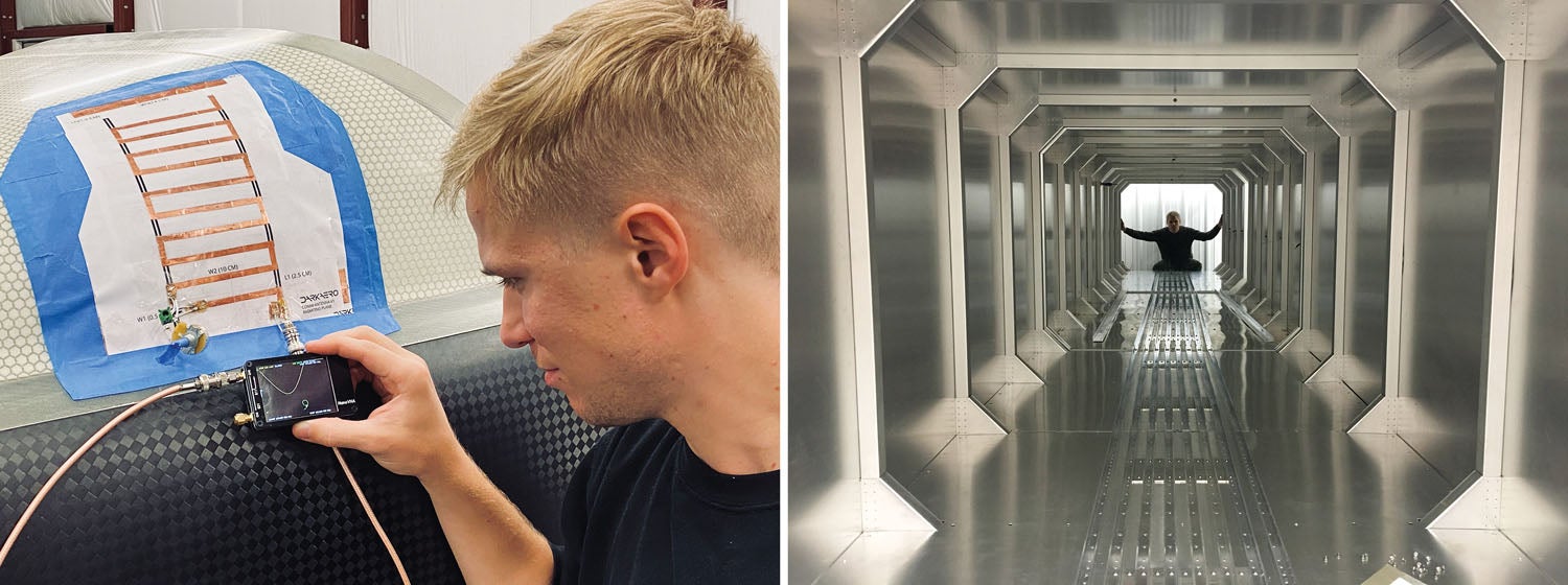
KP: River, you are the electrical engineer for the project. Can you talk a bit about your unique ladder antenna concept?
River: For the DarkAero 1, we want to keep the outside as aerodynamically and aesthetically clean as possible. This means embedding our antennas inside the fuselage. This is a problem though, because the majority of the airframe is carbon fiber composite, which shields radio signals. This is why we made the turtle deck out of fiberglass, which is radio-transparent.
Not only is it challenging to fit all of our antennas in this small space, it’s particularly difficult to fit long vertical antennas like the com antenna. We came across an interesting [academic] paper for a meander dipole—a slightly modified version of this antenna that you can see on our YouTube channel. It’s a similar concept to the shark fin antenna you see on modern cars that has replaced the traditional whip antenna. Antenna design is a bit of an art, so we’ll definitely be putting our antenna through its paces before integrating it into the kit. In the meantime, we will likely use a backup traditional antenna design to get us flying sooner.
KP: It’s clear from your videos that you get a lot of questions and concern about galvanic corrosion, which can be an issue for metal in carbon airframes. How have you addressed this and foolproofed it for builders?
Keegan: Yes, we get a ton of questions on this—so many, in fact, that Ryley ended up making a YouTube video solely dedicated to the topic. There are three conditions that need to be met for corrosion to occur: two materials of different electrode potential must be present, the materials must be in electrical contact, and an electrolytic bridge must be present between the materials. You need to remove any one of those three conditions to prevent it. We keep galvanic corrosion in mind in the design process and have a few solutions we employ to prevent it. Most of these solutions come down to proper material selection or electrical isolation of corrosion-prone areas.
KP: What things do you think you’d do differently if you had to do it over again? Or, say, on a DarkAero 2?
Keegan: There are a lot of things we learned from building molds that would cut down the development time of tooling if we were to do it all again. In the beginning we thought we might be able to directly 3D print the molds for the aircraft. We spent a lot of time researching and testing this, only to come to the conclusion that it wasn’t a great approach.
Ryley: There is still a lot of room for improvement in mold manufacturing and tooling. We came up with a method that worked for us, but I have more ideas I’d like to explore to take our tooling to the next level.
KP: Any final thoughts?
Ryley: One of our goals with sharing our journey through our website and social media channels is to give a window into what it looks like to take a project all the way from an idea to reality. For aircraft, a big piece of the development puzzle is overcoming manufacturing challenges. Manufacturing dictates a lot of aircraft design, and that’s also where there are so many areas for improvement. There is a frontier that exists in new manufacturing approaches and technologies that ultimately makes it possible to build a better aircraft. We think the DarkAero 1 represents that frontier.
KP: Well said! Once you’ve finished your flight testing, we look forward to doing a flight review of the DarkAero 1.


here is a material with Astonishing properties, maybe it might fit into your endeavor
I think Its a blend of urethane and nylon.
https://www.redwoodplastics.com/materials/tuffkast/
Comments are closed.