We are almost to the end of our romp through the solder pads. We’ve learned about the solder itself, and now it is time to talk about the hardware. Or, if you please, the hotware.
Soldering irons come in so many types and sizes it is going to be difficult to cover all varieties. Back in the day, when we were using vacuum tubes and soldering wires directly to tinplated steel chassis, the “iron” was really an iron: Bakelite handle, long thin metal tube about as long as a soda straw with a heating element in it and a soldering tip about the size of a sugar cube. You could burn up a yard of 60/40 wire solder in a single pass without the iron breaking a sweat. I haven’t seen a real one in about 30 years, but I understand some homebuilders keep them around for fastening small control wires to steel fittings. Early technicians used them on those newfangled PC boards where they almost immediately earned the nickname “board burner.”
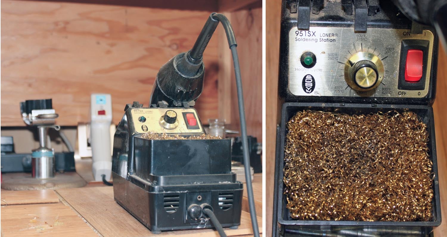
Today’s irons are tiny by comparison, and most of them come as part of a solder station, which consists of a temperature controller, a holder for the iron and a tip wiper to remove oxidized solder from the tip.
Solder stations run the gamut from a plain formed-metal place to rest the iron with no extra goodies (~$15) to the temperature gauge double-iron device with dual solder-wipe stations and some sort of vacuum device to suck up molten solder ($200+). Me? I settled a long time ago for the single 30-watt iron with a calibrated temperature control and a “bathtub” that came with a sponge soaked with water to wipe the tip of the iron off to remove the oxidized solder.
A word about that bath: Sponge-water will do the job…sort of. The best thing for basic soldering I’ve ever come across is to replace that sponge with a thick pad (about as thick as a bar of soap) cut to fit the bath of brass shavings. My brass pad is now about 15 years old and gives no signs of age. It does a much better job of cleaning the tip and is a lot faster.
It took about a month before a couple of pencil marks appeared on the unmarked dial on my station. One is for regular old PC board part soldering and one is for desoldering (more later). And, of course, full rotation balls-to-the-wall* for soldering big pieces together. Later measurements showed this to be tip temperatures of 550°, 700° and 800° F respectively.
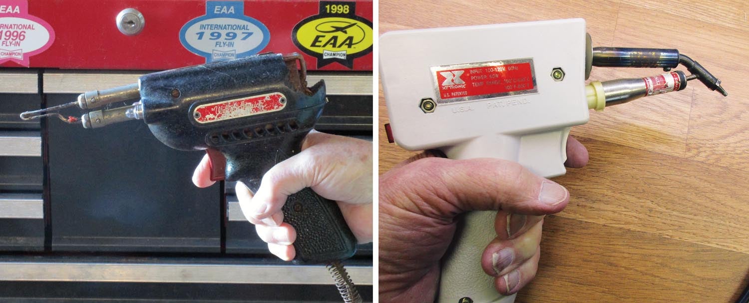
I also keep in my soldering arsenal a very old soldering gun from my time in high school fixing television sets. As you can see from the image, it has taken a couple of falls and is scratched up but still does its 100/150-watt job heating very large pieces. Then again, I’ve picked up a few falls and scratches 65 years later myself.
Desoldering
So, we’ve soldered it together but for whatever reason (part failure, wrong part, etc.), we want to remove the part from the board. The first problem is how to remove the solder so we can take the old part out.
On a PC board think about it. Sure, you have to take the solder off of the back side of the board, but when you soldered that part in (if you did it right with enough heat and enough solder), that board wicked up enough solder to not only solder the pad on the back side of the board, but the copper “tube” inside the hole in the board and the pad on the top side of the board as well.
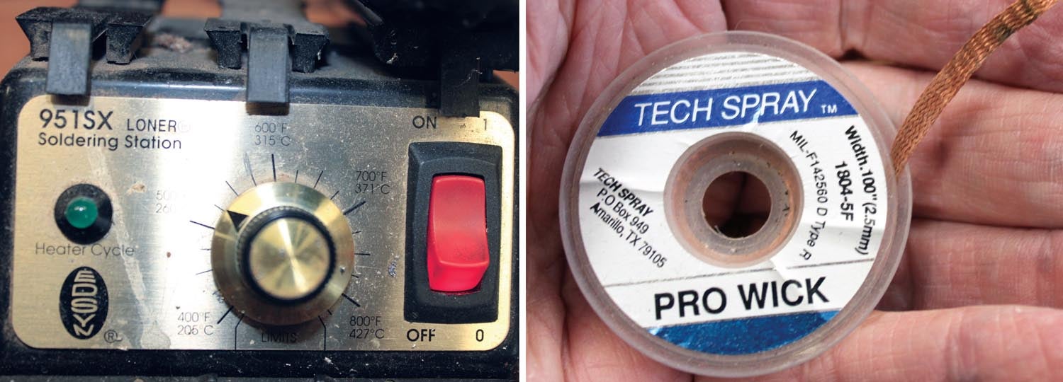
The first tool in our armory for desoldering is what we call solder wick. It consists of a rather thin piece of copper braid that has been drenched in flux and allowed to dry. The solder wick is held onto the solder joint to be cleaned off with your left hand and the relatively hot (second mark on the temperature controller) soldering iron in your right hand is applied to the outside of the soldering wick. The wick sucks up the solder and the joint comes clean. Sounds easy? It takes practice.
Besides, you need to take the solder off of the bottom of the PC board pad plus the solder inside the little copper tube plus the solder on the top PC board pad. It is an art and you will destroy several boards in the learning process.

There are a couple of other tools in the chest to remove solder, mostly by suction. The most prevalent is called a “solder sucker.” It is comprised of a small Teflon tube at the end of a long plastic cylinder with a rubber plunger affixed to a spring inside. You melt the solder, hold the Teflon to the solder, pull the trigger to release the plunger and slurp goes the solder up into the tube. Another way of doing this is with an (expensive) solder gun specifically built for the job. When you plug the gun in, it immediately starts to heat the tip, the tip is applied to the joint, you pull the trigger and an electric vacuum pump inside the iron spins and slurp goes the solder into the cold body of the iron.
Two tricks remain.
One, what is the most expensive “tool” in the shop when working on an aircraft? You. How many minutes (or seconds) of your time is a 10-cent resistor worth when trying to wrestle both of the leads out of the board at the same time? Take a big pair of cutters, cut the resistor (capacitor, IC, transistor) into pieces and pull each lead out of the board separately.
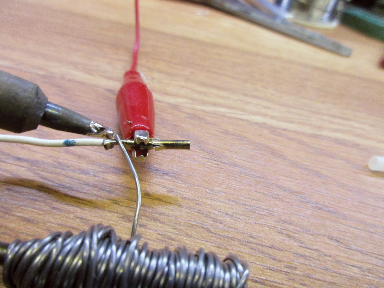
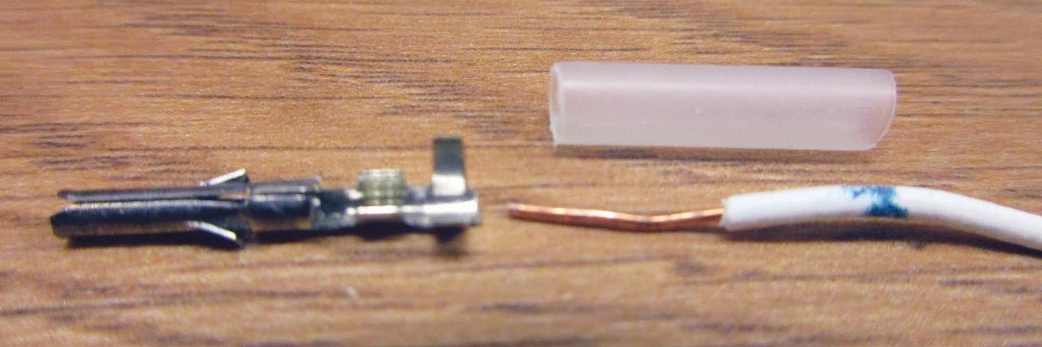
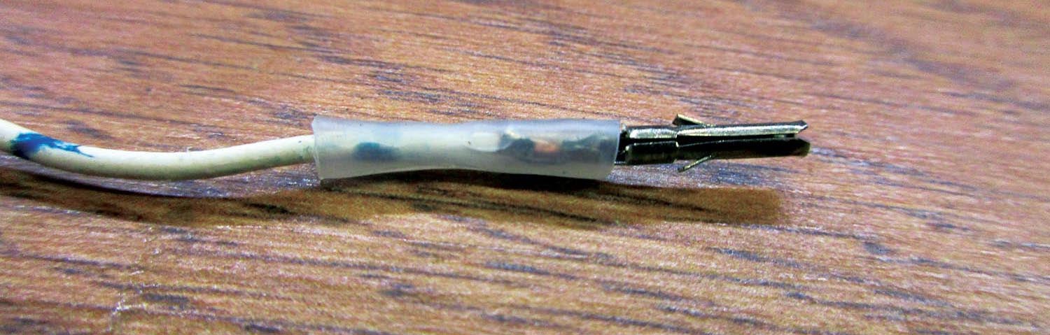
Two, when connecting a wire to a pin of a connector, some pins are meant for solder and some for crimping. Me? I like to either solder and/or crimp and then solder again (belt and suspenders). The question becomes how do you keep the solder from flowing down into the pin and rendering the pin unusable? The answer is to use the cheapest tool in the chest, a simple alligator clip. The back of the pin gets hot enough to melt the solder, but the alligator clip acts as a heat sink to keep the end of the pin from getting solder on it. Do not forget the shrink sleeving over the back of the pin or the wire will vibrate and break when you least expect it (like over the mountains, in the stuff and low on fuel).
Wow, enough of solder. Let’s start building stuff next month. Until then…Stay tuned…
*Lest you consider this an obscenity, it comes from the early railroad days when the steam gauge in the engine cab also had a circular metal cylinder and a center rotating post with brass balls affixed with small very thin wires. The more steam power the engineer commanded with the throttle, the farther out the brass balls swung until at maximum power the balls were bouncing off the cylinder walls and making a wonderful racket. This was called running “balls to the wall.”


