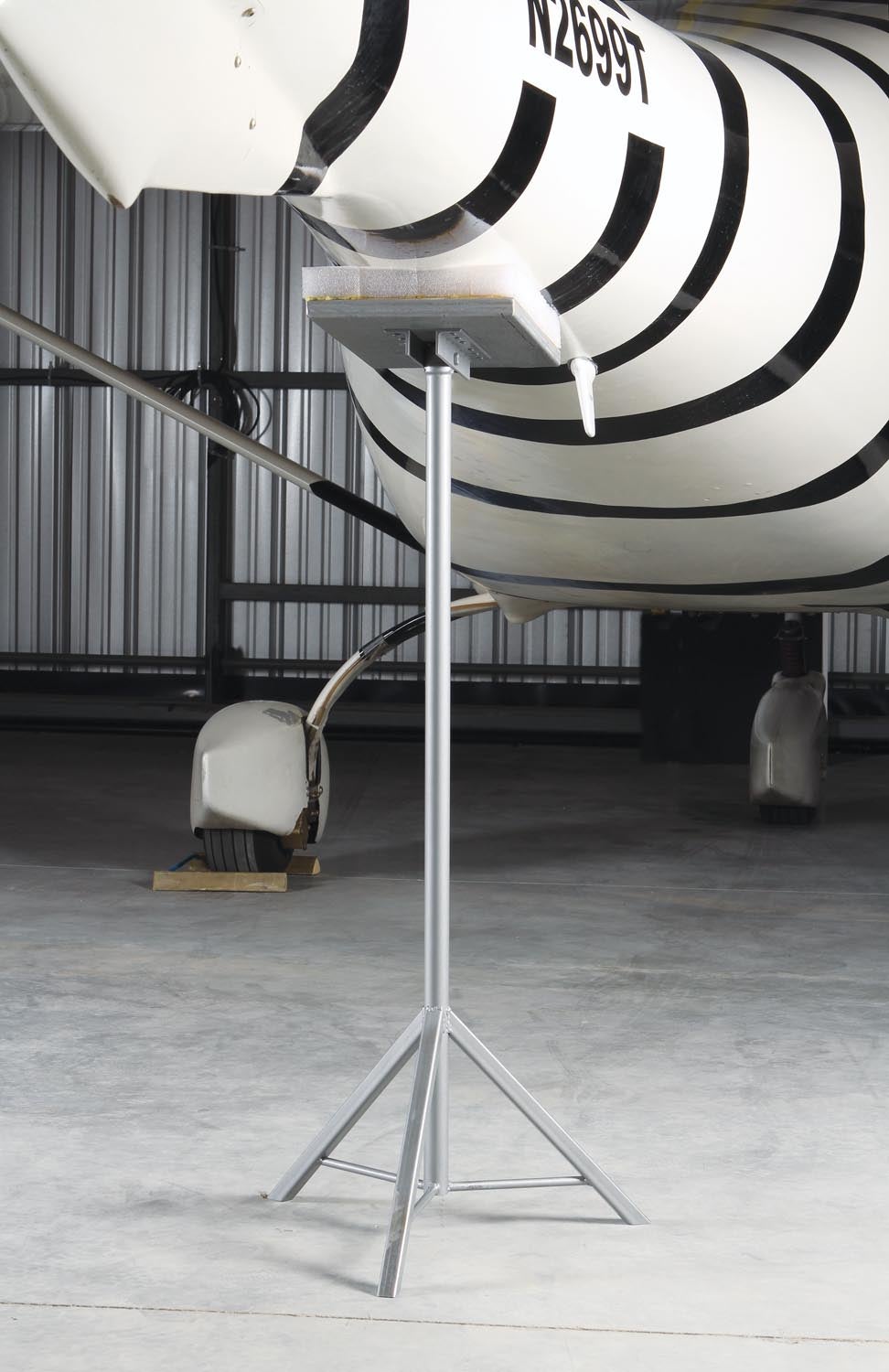
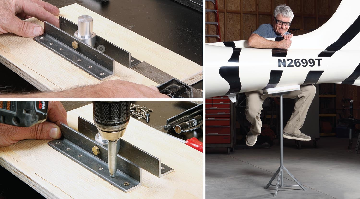
the tail boom innards, be it for annual ELT inspections or to check control riggings. The little fin to the right of the stand is the transponder antenna.
I decided I needed a tail stand after my transponder inspection last spring. A normal transponder inspection is pretty basic: Turn on the avionics and, after everything boots up, a technician walks around the airplane with a fancy (and expensive) gizmo that measures both the content and output signal strength of your transponder. If all goes well, you get a logbook entry, pay and go home. Other than it being the first time at a new shop (Accurate Aero in Minden, Nevada), I expected the procedure to be routine.
This time around my transponder output was low—way below the required level. This was a surprise because I thought my system was hunky-dory. In fact, just before the inspection, I had downloaded an FAA public ADS-B performance report (PAPR) from a recent flight. It showed no red flags or failure indications. To quote the FAA’s website: “PAPR data provides information on the performance of an aircraft’s ADS-B system for a specific flight and will verify proper ADS-B system operation or identify specific parameters received by the FAA’s ground system which failed to comply with established standards.” The PAPR report, however, does not count as a transponder inspection. It only reports what the system picked up on the specific flight in question and does not measure or confirm the transponder signal strength.
I wasn’t sure how the guys at Accurate Aero would react. I’ve heard that some avionics shops don’t like dealing with Experimental/Amateur-Built aircraft. Pull the panel in a certified aircraft and you’ll find all the wiring neatly organized. Pull the panel in an Experimental and there’s a 50-50 chance it will look like a spaghetti bowl of wires instead of resembling a professionally wired certified plane (the latter being the standard of KITPLANES® subscribers/builders, right?).

I had to give it up for the crew at Accurate Aero! After double-checking their equipment, they brought out their head guy, Mario Filice, who suggested a few quick checks to see if they could determine the issue. First, they pulled the transponder from the tray (thank you Garmin for making that easy) and plugged in a “known-good” unit from their shop. Same result. Next, they checked the connections from the transponder to the Garmin GDL 82 ADS-B unit and from the GDL 82 to the antenna. For that, I had to crawl into the tail boom to disconnect the coaxial from the antenna. But not before having someone “spot the tail” to keep it from crashing down on the pavement. Like most lightweight tri-gear aircraft, on mine, you can easily lift the nose gear off the ground by pushing down on the tail boom. Which means that anytime you’re working in the aft end, you need a spotter or something under the tail to keep it from doing a wheelie.
It turned out the antenna was the culprit. A simple swap to a known-good unit from the shop and the transponder was squawking at full strength. Go figure. For whatever reason, the dipole antenna I had been using wasn’t broadcasting anymore. The antenna they used for the test was a RAMI AV-74, shark-fin style antenna. I ended up buying it and took it home to install it.
Back at the hangar, I set about figuring out how and where to install the new antenna. Before climbing into the boom, I set up the usual stack of lumber and foam under the tail. While certainly stable enough, I realized it was a Mickey Mouse setup.
What I needed was a dedicated tail stand. Something both sturdy and worthy of a professional-looking shop. In other words, a perfect project for the Home Shop Machinist!
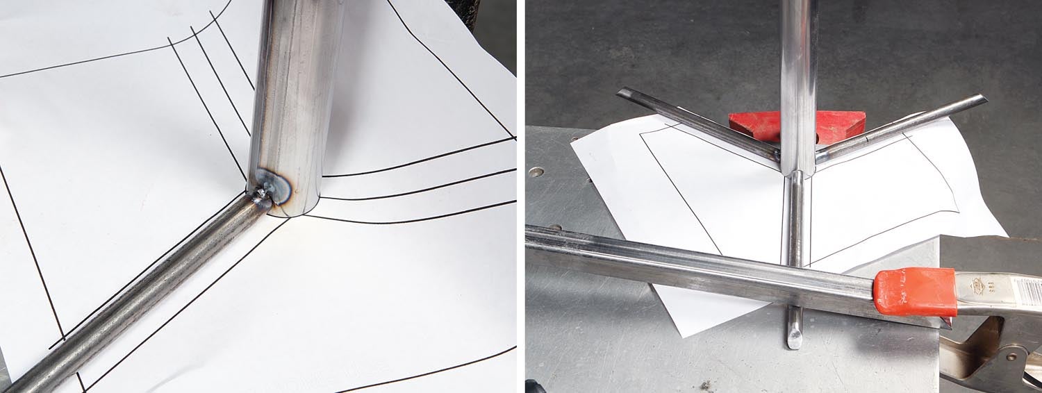
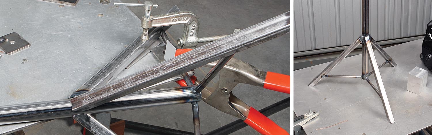
The design I came up with is similar to the axle stands featured in the March 2019 issue of Kitplanes®. The main difference is that this is a tripod design. With four-legged stands, the wider the stance, the more they are affected by uneven floors.
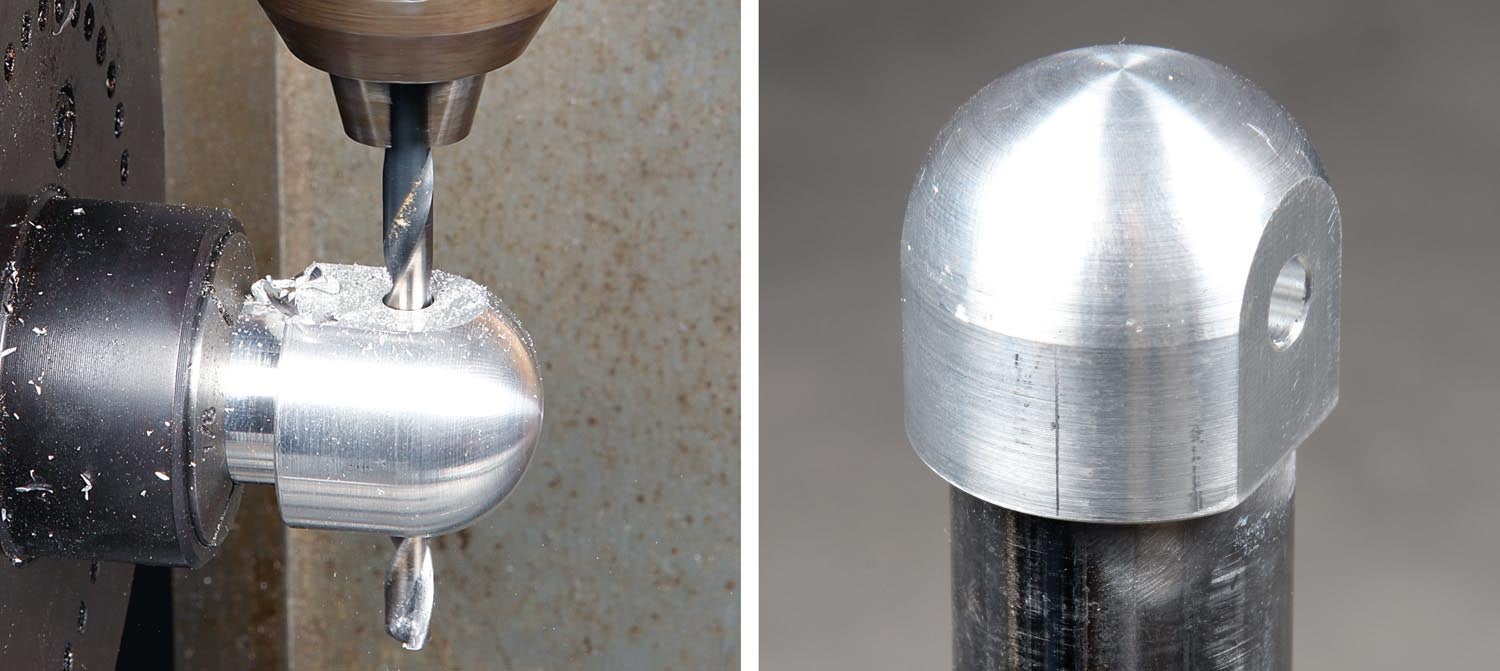
A typical commercial tail stand has a shackle or yoke with a cross pin to attach it to a corresponding tie-down point on the tail. The Jabiru doesn’t have that feature, so I designed my stand with a pivoting 8×12-inch plywood table. Together with a generous foam pad to protect the paint, the table spreads the load over a wide area.
While the single post may look spindly, it easily handled my full weight (180 pounds) with nary a wobble. In use it will never see that much load. I figure during a typical ELT inspection, the most it will need to support is about 80 pounds and only slightly more if I have to reach the antenna connection.
The antenna install went well. I included the ground plane recommended by the shop, and when I went back for a retest, it passed with flying colors.
Download the detailed drawing of the LSA tail stand. That’s it for now. Time to get back in the shop and make some chips!


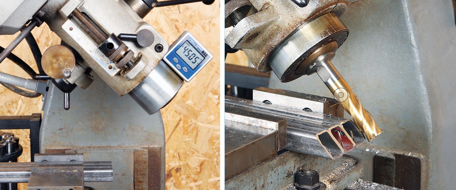
A beautiful piece of work that required a:
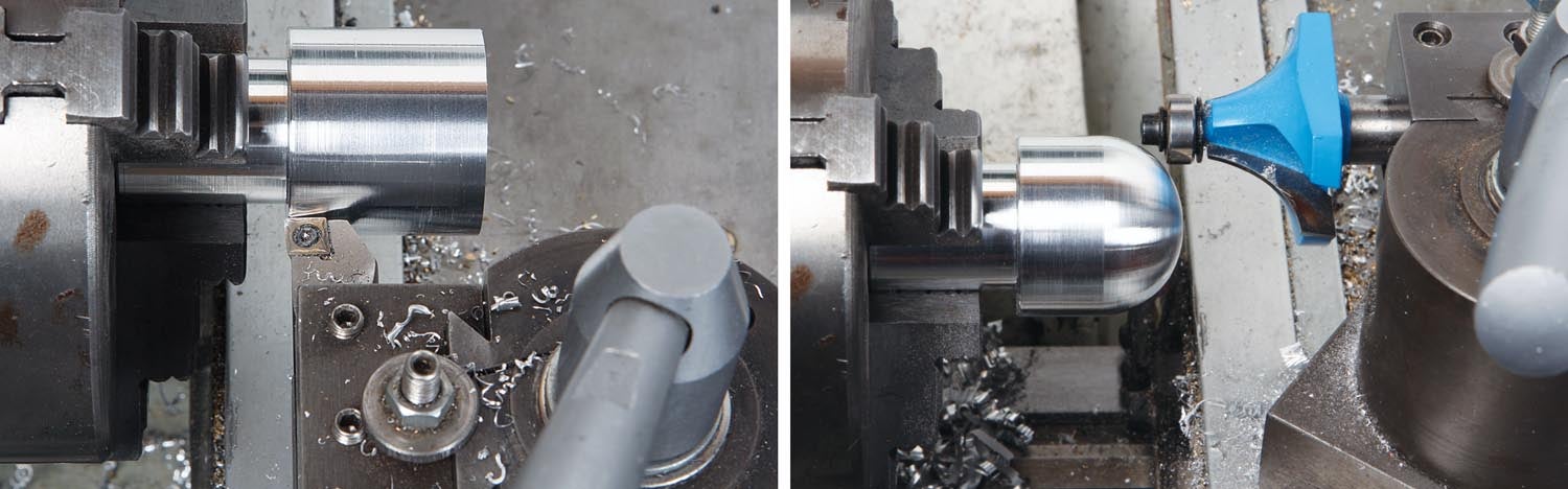
Milling Machine
Router
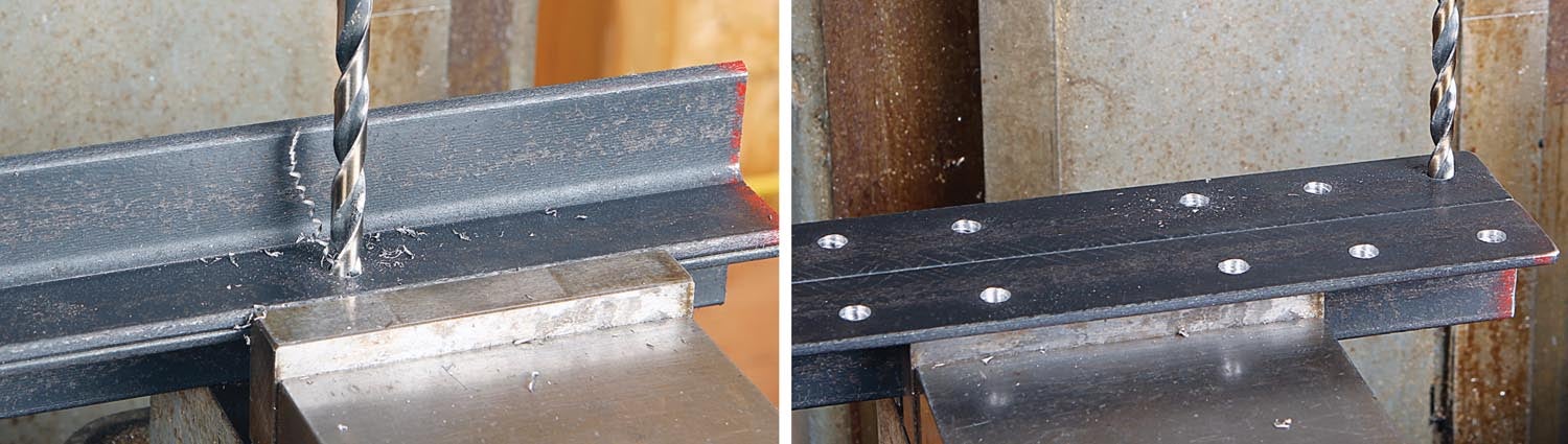
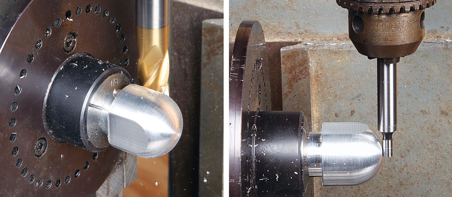
Drill Press
Saw
Welder
A $60 pipe stand from Amazon would do as well.
But then you’d miss the opportunity to buy and learn how to use all those tools.
Comments are closed.