The call came. At the other end was Kevin King, the owner of the resurrected Blue Mountain EFIS from last month’s Home Shop Machinist column.
“It’s here. My GRT display has arrived.”
Kevin hadn’t expected it for another month, so it was more than a pleasant surprise. Since March 2020, just about every aviation-related thing he’d ordered had been taking “COVID-time,” which was normal time multiplied by two or three. The longest wait was for a carbon fiber prop that took almost a year. Even service work was taking forever. Kevin sent in his com 2 radio to be checked out, and it took twice as long as estimated. So when GRT Avionics came back with an estimated 12 weeks for a new Horizon EFIS, Kevin was expecting 15 weeks or more. Instead, it arrived in eight.
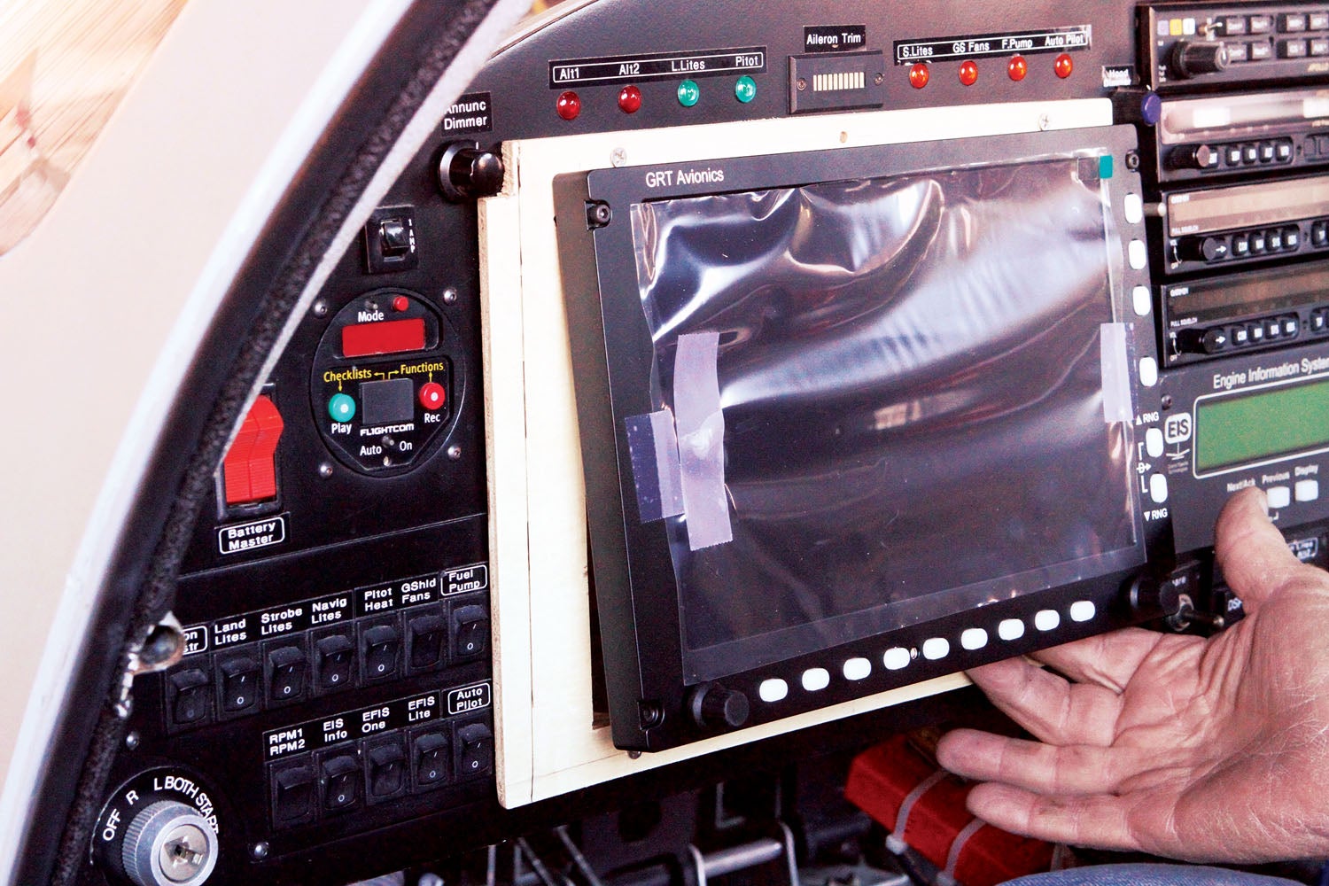
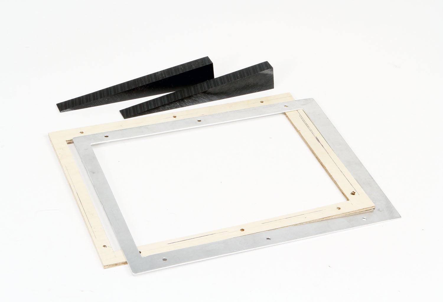
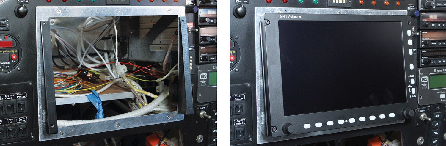
The arrival of the panel meant we had to reboot the plan to fit the new screen. Kevin didn’t want to remake the entire panel, at least not for the time being. So the question was how to adapt the existing opening to a slightly smaller GRT Horizon 10.1-inch display. Kevin had downloaded the installation manual from GRT’s website, which included a template drawing with locations for the mounting screws. I sketched out a basic idea and made a mock-up frame out of 1/4-inch plywood (actual thickness 0.190 inch) to verify the fit and locations of the mounting screws.
The twist to this story was that Kevin wanted the display to be angled up slightly to his line of sight. To determine that angle, we used some extra-long 6-32 screws to loosely hold the display onto the plywood mock-up while Kevin varied the angle until it was just right, which turned out to be 10°. The GRT installation manual provided details on how to calibrate the gyro sensors to compensate for the display being mounted at various angles, so we were good to go.
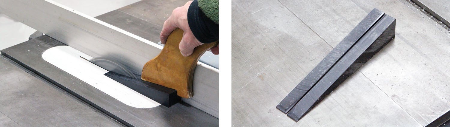
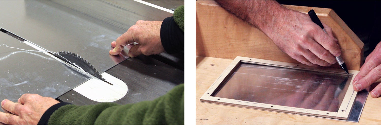
Back at the shop, I used the plywood mock-up to lay out the outline, the opening for the display and the attachment points onto a fresh sheet of 0.063-inch aluminum. To achieve the angle Kevin wanted, I decided to make wedges out of black Delrin plastic. Delrin is a hard plastic that machines well and can be drilled and tapped for standard screw threads. I used 6-32 flat head screws to fix the wedges to the adapter and then, with the GRT display in position, used a transfer punch to mark the wedges for the GRT mounting screws.
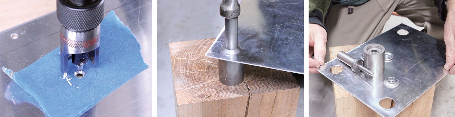
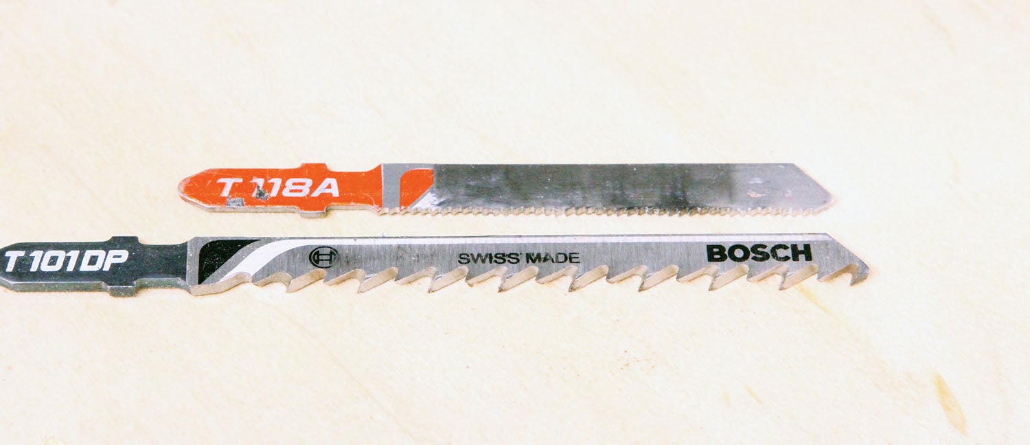
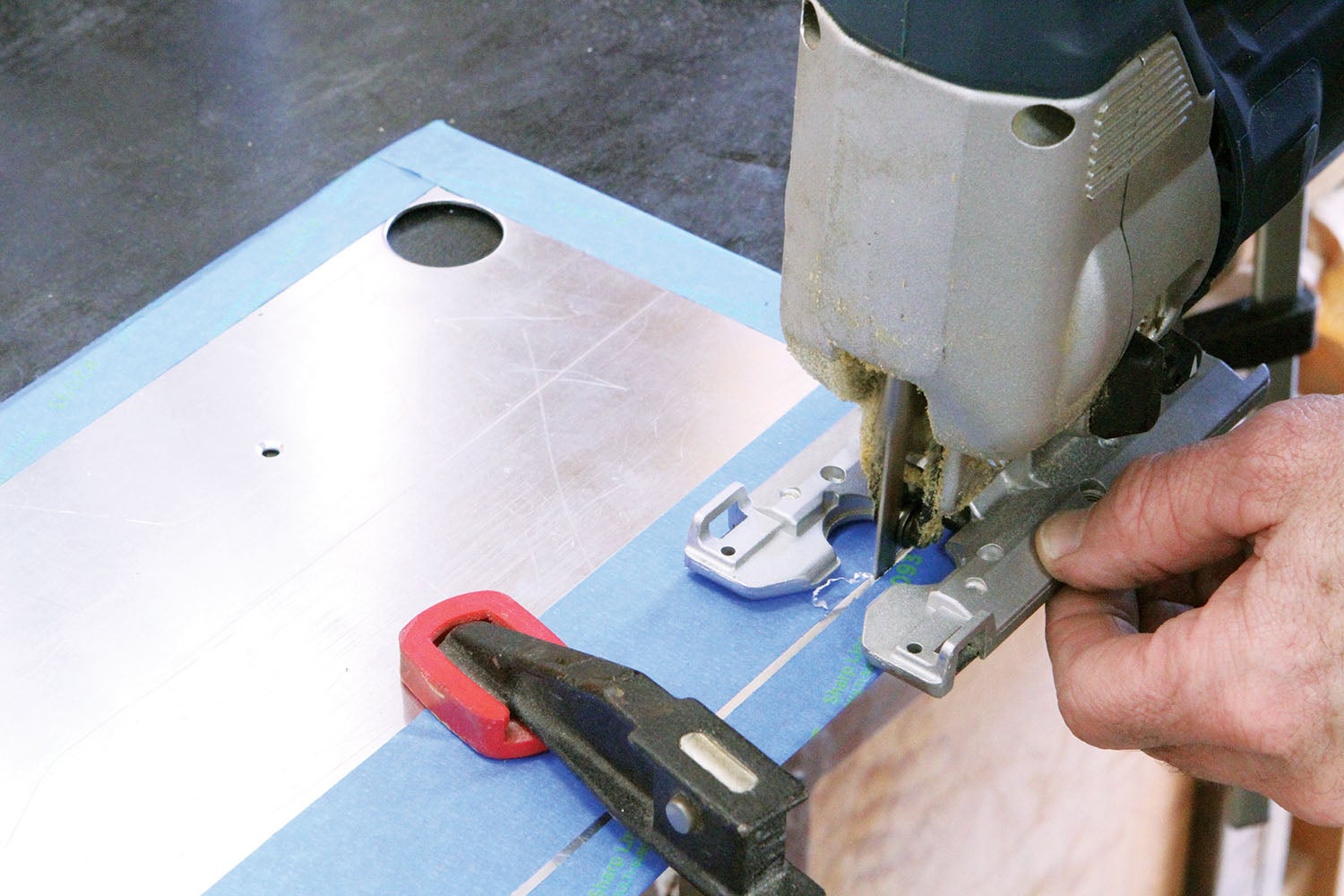
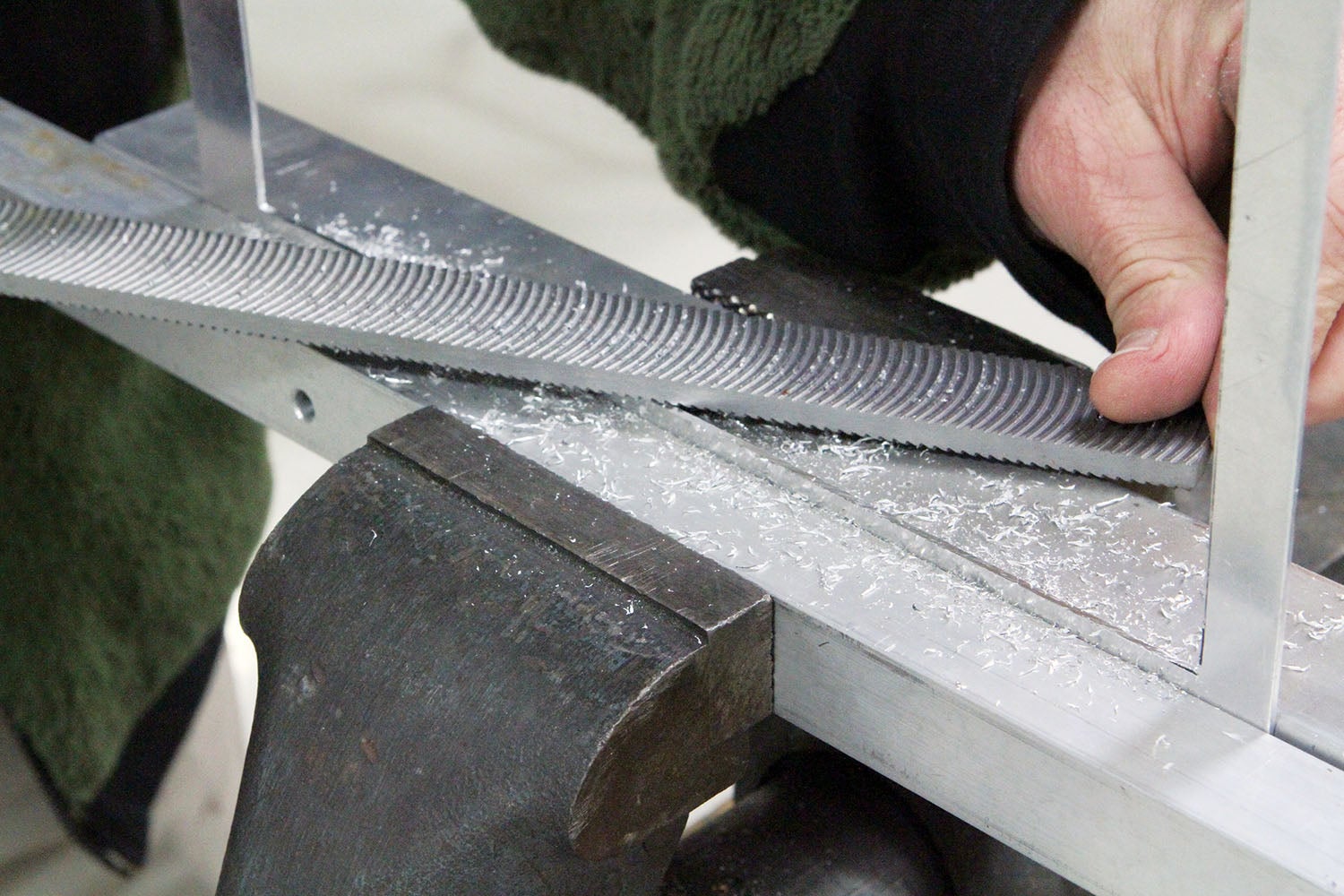
To cut the opening for the GRT display, I used a knock-out punch to make holes in each corner and then clamped the workpiece to the edge of my bench and cut the four sides for the opening using a Bosch jigsaw with a fine-tooth metal-cutting blade. The resulting edge was a bit ragged but cleaned up quickly and easily using a mill file with a curved-tooth profile. Using a jigsaw and a hand file may seem a bit low-tech. I could have used the milling machine, but the thin material and large size made it a good candidate for simply clamping it to the bench and getting after it with the jigsaw.
That’s it for this month. Time to get back in the shop and make some chips!
![[Credit: Radiant Technology]](https://www.kitplanes.com/wp-content/uploads/2026/04/550095_5165745cc27748a598699799d796fd94mv2.jpg?w=218&h=150&crop=1 "Radiant Technology Unveils SafeGyro")


Is the bottom edge of the GRT display open or did you also enclose it?
It’s open.
The bottom of the panel face frame is about an inch from the panel, but the gap between the panel across the bottom of the EFIS housing is about 0.10-inch.
–Bob
Cool stuff! Wonder if this would work for a G3x touch.. as long as you have the AHRS externally mounted
Comments are closed.