Finding an angle on staying grounded.
This is one of those “features” of a plans-built airplane wherein the builder gets to figure it all out. In this case, how to tie down the airplane. The nice thing is that this is a smaller project that I was able to do in about an hour or so.
The Thorp T-18 is a “bent wing bird” (like one of my other favorite aircraft, the F4U Corsair) with a break mid-span, and the wing joint provides a logical location for the tie-down brackets. The outer wings’ forward spar attaches by sliding between very stout fittings on the center spar, loading the two 3/8” bolts in double shear. Nice and strong. The business end of the bracket will be in this mid-span joint and require a slot to be cut in the gap cover. That and longer spar bolts are the only modifications. Win-win.
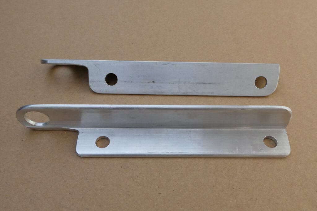
My idea was to use those two bolts, albeit with a longer grip length, to secure the tie down brackets to the forward face of the center spar. I went with two pieces of 0.75 x 0.75 x 0.125 inch 2024-T6 angle extrusion, though 1×1 inch angle would have allowed for a slightly larger hole for ropes, hooks, etc.
I started with holding the first stick of angle up to the center wing and using the TLAR (That Looks About Right) method to determine a length to span the bolts and with enough added to extend below the lower wing surface. It worked out to 7.35 inch long overall, with 1.50 inch protruding.
The key thing to remember is that you will be cutting off one flange of the angle below where the bolts go, and leaving the other leg of the angle longer. As with other projects, use your sharpie to write on the metal as to what gets trimmed off and what gets kept. Otherwise, you might make a saw cut in the wrong place and wind up having to start over. Don’t ask me how I know this….
After getting the angles cut to length I measured for the upper bolt hole location so that the top of the angle is nearly flush with the top of the spar, and thus in no danger of hitting the gap cover. Note that with the 0.75 inch angle, the hole center is a bit offset from the flange centerline so that the bolt head won’t dig into the radius.
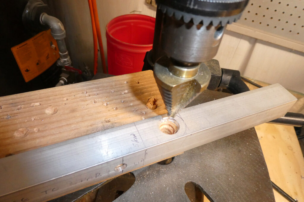
The first hole was drilled on the drill press, starting with a 1/8 inch bit and then increasing the bit size in steps until I had a clean 3/8 inch hole. The real trick is getting the second hole in just the right location. John Thorp designed the T-18 to three decimal places; his drawings most closely resemble the tightly dimensioned drawings that I created and updated at the major airframe companies. My problems were: (1) Are the existing spar holes per the drawing, (2) even if they are, can I hit that dimension exactly by laying out the hole centers using a scale or calipers?
Fortunately, I can let the spar itself do the work so that I get a precise location with these close-fit holes.

The angle was put into place with a 3/8 inch (AN6) bolt in the top hole, and then held into place while a 3/8 inch drill bit was placed in the other hole and turned by hand. The result is a tiny drill start that precisely locates the center of the lower hole. Follow that with a spring punch and the drill press and you have the second hole exactly in line with the lower spar bolt.
With the drilling done and checked against the spar, it is time to cut the lower end to shape. Drill a 1/8 inch hole for the corner radius and bandsaw to it. After that, it is all an exercise in sanding and filing to round off and smooth corners.
The tie-down openings themselves are 5/8 inch in diameter. I could thread most ropes through the holes, but just in case, I’ll probably obtain a pair of carabiners (good ones, not the key-chain kind) to put through the holes and run any tie-down ropes or chains through the carabiners. When not in use, they get stowed in the cabin. I did not fully sand down the last remaining amount of the cut off leg, preferring to have the little bit of extra beef, and the air won’t care.
How strong are the brackets? The thinner, aft side of the tie-down hole is about 0,175 x 0.125 inch, giving a cross-section of 0.02188 square inches. Staying conservative, multiply that by 50,000 psi tensile strength for 2024-T3 and we get approximately 1,093 pounds if I did the math right. Assuming that both sides of the hole are carrying about the same load, then each bracket should be good for at least 1,100 pounds, again being very conservative. In other words, tie-downs anchored in turf will likely pull out first. Strong enough, even if my calculations are off by a lot.


How do you use it?
Do you have pics of this in use??
Comments are closed.