I first met Bob Goodman on a trip to the ’93 Sun ‘n Fun fly-in in Lakeland, Florida. He was a friend of a friend who was there with his Piper Seneca. We didn’t get a chance to talk until we were in the rental car and waiting in the traffic jam that indicates you have arrived at the world’s second biggest homebuilt aircraft fly-in, but what he had to say intrigued me.
Bob was interested in putting something other than a Lycoming on the Van’s RV-4 he was building, and one of our mutual friends told him that I was an engine guy. We spent a couple of days walking the flight line and looking at and talking about engines. A friendship was born in addition to an agreement to work together on an epic auto-engine conversion for his airplane. Bob’s wish list included a cruise speed of 150-160 mph, easy and economical repairs, a decent climb rate (at least 1500 fpm), and it all had to fit inside the stock RV-4 cowling.
The Concept
Bob wanted something different. I think that one of the reasons that we hit it off so well in the beginning is because something different is the nature of my life. I have been working with turbo auto engines for 25 years, and I was enthusiastic about the prospect of working on this project. One of the reasons Bob picked the RV-4 was its reputation for fighter-like handling. In many ways, his choice of aircraft proved to be the foundation for success. The aircraft’s designer, Dick VanGrunsven, deserves much credit. The RV-4s reputation for excellent handling is well known, and in Bob’s case, except for an aileron trimtab, the airframe has proven to be totally trouble free.
In this article, I will detail our successes and failures. To answer the questions on everyone’s minds now: Our engine costs more than a Lycoming; it weighs exactly the same as an O-320; it took a lot longer than a Lycoming to install; and it performs better than most Lycomings. And, yes, we had to modify the cowling. Simply put, we fell short of our cost goals, but we exceeded by a wide margin our performance expectations. We achieved the power of an O-360 with the weight of an O-320, but it wasn’t easy.
Picking an Engine
Initially, we looked at several engines, including a Mercury V-6 outboard, a pushrod Chevy V-6 (2.8-3.1 liter) and the Nissan 3.0-liter SOHC from a 300ZX. The Dodge Intrepid V-6 was also a contender given its compact size. Many other V-6s were eliminated due to the width constraint of the RV-4 cowl.
We were also looking closely at Subaru engines, and we found a deal on one of those hail-damaged 2.2-liter salvage engines that were distributed to dealerships a few years ago. We bought it sight unseen. The Subaru EJ22 has the most favorable power-to-weight ratio of any of the engines we studied, and it also has an outstanding reputation for smoothness and durability. The horizontally opposed configuration was also the best fit for the shape of the RV-4 cowl.
But it wasn’t until I actually had this engine in hand that I realized what a great decision we had made. Two people could lift the engine (with all bracketry and intake manifold installed) into the back of a Porsche 944 and close the lid. We joked that this should have been our requirement all along.
Planning the Installation
Several things became obvious when we lifted the stripped engine onto a carefully shimmed platform in front of the leveled fuselage with engine mount install.
First, two men can easily lift the entire engine. The weight is 179 pounds–close to the weight of the cast iron Nissan block/crank/pistons/rods assembly without cylinder heads or accessory drives!
Second, the engine mount was going to be a difficult problem because there are no convenient bracket attach points on the firewall side of the engine. The timing belt cover uses all that space.
Major Fabrication Job No. 1: Build the engine mount and devise a way to attach it to the engine.
Third, a concentric-drive propeller-speed-reduction unit (PSRU) was going to work best in this installation.
We had already talked to Chris Ross several times and had decided to use a Ross drive if possible. We shifted the engine fore and aft under the top cowling to figure out the best bellhousing length. Ross offers three different lengths.
It didn’t take long after playing with all the dimensions of the components (a Nissan air conditioning evaporator core to represent a radiator and an AiResearch TO4 turbo) to determine that the best solution was the longest bellhousing, putting the engine near the rear of the engine compartment. This would allow room for one radiator in the front of each chipmunk cheek in front of each head. Two radiators positioned this way would allow us to use the original air inlets on the cowling as supplied by Van’s.
Because of the slope of the cowling, the clearance between the top of the engine and top cowling increased as the engine was moved aft. We knew before we ever saw the engine that the somewhat massive stock intake manifold would not fit. But we were disappointed to learn that not even the stubs of the intake manifold that bolt to the heads and contain the injector mounts would fit. There was not enough clearance at the top of the chipmunk cheeks for the injectors and fuel rails.
Major Fabrication Job No. 2: Design and fabricate an entirely new low-profile intake manifold and fuel system including the injectors and fuel rail. The Lycoming has no manifolds on top of the engine, so the cowling is the wrong shape for an engine like the EJ22.
We ordered a PSRU with a four-planet gear set and a 2.17:1 ratio from Ross Aero. While we were waiting, Bob made a replica of the firewall out of 34-inch plywood and carefully plotted the centerlines and attached the stock RV engine mount.
Building the Mount
We used the Ross method of building an engine mount: We mounted the 34-inch plywood firewall replica horizontally to a frame of 2x12s (edgewise) to stiffen it and to elevate the work surface. A plumb bob suspended from the ceiling was used to position the firewall centerline and thrust centerline. We then shimmed the table to exactly level and bonded it to the concrete floor with 20 quarter-size dabs of Bondo.
With the replica firewall securely bonded level to the floor, we fabricated a box from 34-inch plywood that supported the engine/PSRU (by the harmonic balancer/pulley) in position. We used a SmartLevel that has a digital readout on the propeller flange to achieve our down-thrust (6) and side-thrust (2.5 left) and modified the support box to get just those numbers. We then shifted the box on the plywood firewall to center the propeller flange under the raised plumb bob that marked the thrust centerline of the airplane. We had to shift the engine 58 inch to the right, and 0.25 inch up to compensate for the tilted engine. We screwed the box to the plywood firewall to prevent shifting.
We worked with PVC pipe and hot glue to help us visualize how the tubes would fit. The design work at this stage is the most difficult because nothing is in place, and every component has to be considered at once. And with a turbocharged engine, there are a lot of components, many of them extremely hot. A great deal of thought went into keeping the hot items isolated from the rest of the engine components and away from the pilot.
Another design consideration was keeping all of the heavy components far forward. We even maximized the position of the engine as far forward as possible by using every millimeter of cowling. Van’s Aircraft supplies the cowling with a little excess length, and we used all of that extra length. The tandem-seat RV-4 has an aft-c.g. problem, especially with the O-320 engine and a back seat passenger, so each component was placed as far forward as possible, with particular attention paid to heavy items.
We also planned to move the battery into the engine compartment, and put the two electric fuel pumps in the well between the pilot’s feet where the battery used to live.
Radiators
Because we needed a pair of custom radiators made, as soon as we had the engine in place on the replica firewall, we jigged the cowlings and determined the best way to fit the two exchangers. I had a good idea of what our cooling requirements were going to be from previous experience fixing a cooling problem on an NSI Subaru conversion.
Once we had an idea of how much room we had, I made a Styrofoam replica of the radiator, and we used that to make sure we had enough room for it. The cooling matrix of each exchanger is 8x10x2.25 inches with 14 fins per inch. There are two of these, and they are the mirror images of each other.
I designed it to be a double-pass-style exchanger with minimum end tanks. This had several benefits. The double-pass exchanger is slightly more efficient, achieving a higher temperature drop for its size. Additionally, I was able to squeeze a little more cooling area in because I was able to make the shape of the inboard tank concave to fit around the PSRU and make the shape of the outboard tank convex to take advantage of the curve of the chipmunk cheek. We sent the Styrofoam replica off to a custom radiator shop to have copies made in aluminum.
Fabrication Begins
One of our big decisions was deciding whether to keep the entire engine mount as delivered by Van’s and build a framework on the Subaru engine to adapt it to the Dynafocal mount, or to build a special one-off mount using only the basic framework and landing gear sockets. The design of the RV-4 incorporates the landing gear into the engine mount. We realized after propping a few components like the turbo in place that keeping the stock Dynafocal ring was going to complicate things with many extra tubes getting in the way of the turbo and associated plumbing. Simpler won out over leaving the Dynafocal mount in place. Once that decision was made, out came the hacksaw and carbide wheel, and the Dynafocal ring was history.
I constructed the engine mount of 0.049 chrome-moly in only two sizes: 58 and 1 inch. We could have used a thinner wall thickness, but the thinner tubing is more susceptible to denting, and it can be a bit harder to weld in tight spots. All welds were TIG and back-purged with argon gas. I used a trick rod with high elongation that made the welding a little easier.
The elastomeric mounts are actually BMW front lower control arm bushings. All mounts are double-shear. For jigging while welding, I also had an aluminum replica of the rubber bushing made to hold things in alignment. We have six attach points with any four being able to carry the engine. There is very little play, but the inherent smoothness of the Subaru engine needs little isolation.
As mentioned earlier, finding places on the Subaru engine to attach a mount was a serious problem. We fabricated six mounting ears on the PSRU because not one of the cast-in bosses was in a convenient location to use as a mounting point. I fabricated the top two and combined them with the intake manifold rear two runners. For the bottom two engine mount points, I fabricated two 18-inch chrome-moly plates extending down from the cylinder heads.
I started by fabricating the individual port runners. The openings that permit the air/fuel mixture to flow into the engine were carefully matched to the ports in the heads. After shaping the thin-wall 1.75-inch 6061 tubing that formed the runners themselves, I welded them in and again carefully matched and smoothed the transition to the engine ports. The ports are oval shaped because the engine is a four-valve design.
Fabricating the Turbo Mount and Exhaust
This was Major Fabrication Job No. 3. Initially we planned to put the turbocharger between the engine and the firewall. There was room–but just barely. The oil draining from the turbo must drain back to the engine using nothing more than gravity as a motivator.
A second fabrication and design problem was supporting the 15-pound turbo. It had to withstand engine vibration and g loads. The standard automotive method of turbo support is a thick-walled cast-iron exhaust manifold. The stock Subaru method is a heavy stamped-steel bracket. Because we were not using a Subaru turbo or mounting it in the stock Subaru location, we were on our own.
We didn’t use the stock turbocharger because it is designed to produce maximum low-end torque and response. It is not sized for steady-state continuous operation. Turbochargers are application specific. The tiny turbine wheel and turbine nozzle that drive the compressor into boost at very low rpm for street driving become a major exhaust restriction at medium to high rpm.
This also is not a high-altitude application like most turbocharger applications for airplanes. Our focus was to provide extra power for takeoff and climb. This allows us to use a fixed-pitch prop optimized for cruise and still have acceptable takeoff and climb performance.
The initial plan to mount the turbocharger behind the engine to take advantage of gravity drain back into the stock oil pan was foiled by the firewall toe boxes that allow rudder pedal travel. There just was not enough room to allow the hot exhaust pipes to pass up and down between the upper corner of the toe box and the plastic belt cover that protects the camshaft drive belt. If we had chosen to build a custom cowling, we would have had enough room to mount the engine farther forward.
Major Fabrication Job No. 4: Dry-sump the engine and build a remote oil reservoir. This would allow us to place the turbo tight up against the bottom of the engine and gravity drain to a separate oil reservoir located at the lowest point in the engine compartment. On the bottom of the truncated oil pan, I added light-gauge tabs for the heat shield we would fabricate later.
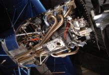
With the turbo oil drain problem solved, we were able to move to construction of the turbine inlet pipes, turbo support brackets, turbine discharge pipe (exhaust pipe) and compressor inlet and outlet pipes. We positioned the turbo as close to the bottom of the engine as we could while leaving room for the heat shield we would make after the engine and mount were on the airplane.
To save weight and insure reliability, we decided to construct the turbine inlet pipes (they run from the exhaust ports in the cylinder head to the turbine inlet) from thin-wall (0.035) 321 stainless steel.
To accommodate 321s thermal growth potential, I added two slip joints and two aircraft ball-swivel joints. These features also make the exhaust system easier to install. The exhaust system leading the gasses to the turbine inlet is the part that gets the hottest and handles the most pressure. The EGT drops several hundred degrees across the turbine, and the pressure at the turbine discharge pipe is zero atmospheric because we have no muffler.
Radiator and Computer Support Brackets
The final step in fabricating the engine mount was building in some brackets to support the coolant heat exchangers and dual engine management computers.
The exchangers need to be projected out in front of most of the rest of the engine to put them relatively forward in the chipmunk cheeks. This would place them behind the opening in the stock RV cowling. For reasons mentioned earlier, we ended up mounting the computers, which were fairly heavy, as far forward as we could in one of the few spaces remaining big enough to hold them–the portside chipmunk cheek. All the support brackets are made from light-gauge chrome-moly.
Final Attachments
After the completion of the radiator support brackets, we reached the stage where we needed to have the engine mount on the airplane to fabricate further components. At this point, we had the replica firewall still bonded to the shop floor with the completed engine mount bolted to it, the propeller spinner pointed at the ceiling.
The engine, PSRU, exhaust system (turbine inlet and outlet pipes), turbo support brackets, mounts for the dual engine-management computers, and radiator support brackets were completely fabricated and bolted in place. Before powder coating the engine mount, I welded on a few tabs to secure wiring and plumbing, a mount for the remote oil filter, and mounting tabs for the yet-to-be-fabricated oil reservoir and airbox/filter.
We were definitely making progress. Next issue we’ll continue with Part 2 of the installation and get this engine running.
Tom Wyatt III has been turbocharging engines for 25 years, but this is his first airplane engine. He is a glider flight instructor, glider towpilot, and he is currently building a Europa. He currently works as a turbocharging consultant and software application specialist for computer-controlled management systems. (Tom Wyatt was killed in a traffic accident early in 2006. Ed.)

