 Some months ago, my engine developed “morning sickness,” which is when it seemed like the start was a bit rougher than it used to be for the first couple of seconds. After a while, it progressed to lasting for 5–10 seconds, during which time it was obvious that the EGT on one cylinder was slower to rise, then would rapidly catch up with the rest of them.
These symptoms can be caused by combustion deposits getting into the valve guides, reducing clearance and causing the valves to stick a little bit instead of freely moving up and down. Often, this symptom shows up only when the engine is cold. When it is running, things heat up, parts expand and a sticking valve can start to move freely again.
If the valves stick too much, a bent pushrod can be the result, causing a valve to remain in a partially open or closed position, which takes the cylinder offline and can cause the pushrod tubes to be compromised, leading to loss of oil and a grounded airplane. In a worst-case scenario, the valves could develop a sticking problem in flight, which could lead to a forced landing. With this in mind, Lycoming recommends doing a “wobble check” every 500 hours or at the first sign of morning sickness, whichever comes first.
The concept of the wobble check is actually pretty simple: Wiggle the end of the valve stem back and forth and see how much it moves. If it is less than the published tolerance, the guides need to be cleaned. If it is more than the published tolerance, then the guides and/or valves may need to be replaced.
Wiggling valve stems back and forth sounds pretty scary but it’s actually a fairly simple procedure and has a lot of steps in common with lapping valve faces, something every A&P should be (but often isn’t) familiar with. If you’re comfortable around engines, it shouldn’t be a problem. If not, you might want to do it the first time with someone who has some experience, if for nothing else than moral support.
OK, Go
The first step in doing the wobble check is to assemble all of the necessary tools and spare parts. Some of the tools aren’t absolutely necessary, but they make the job easier. If you don’t have them already, this article can be your public service announcement to show your significant other to justify getting some new tools.
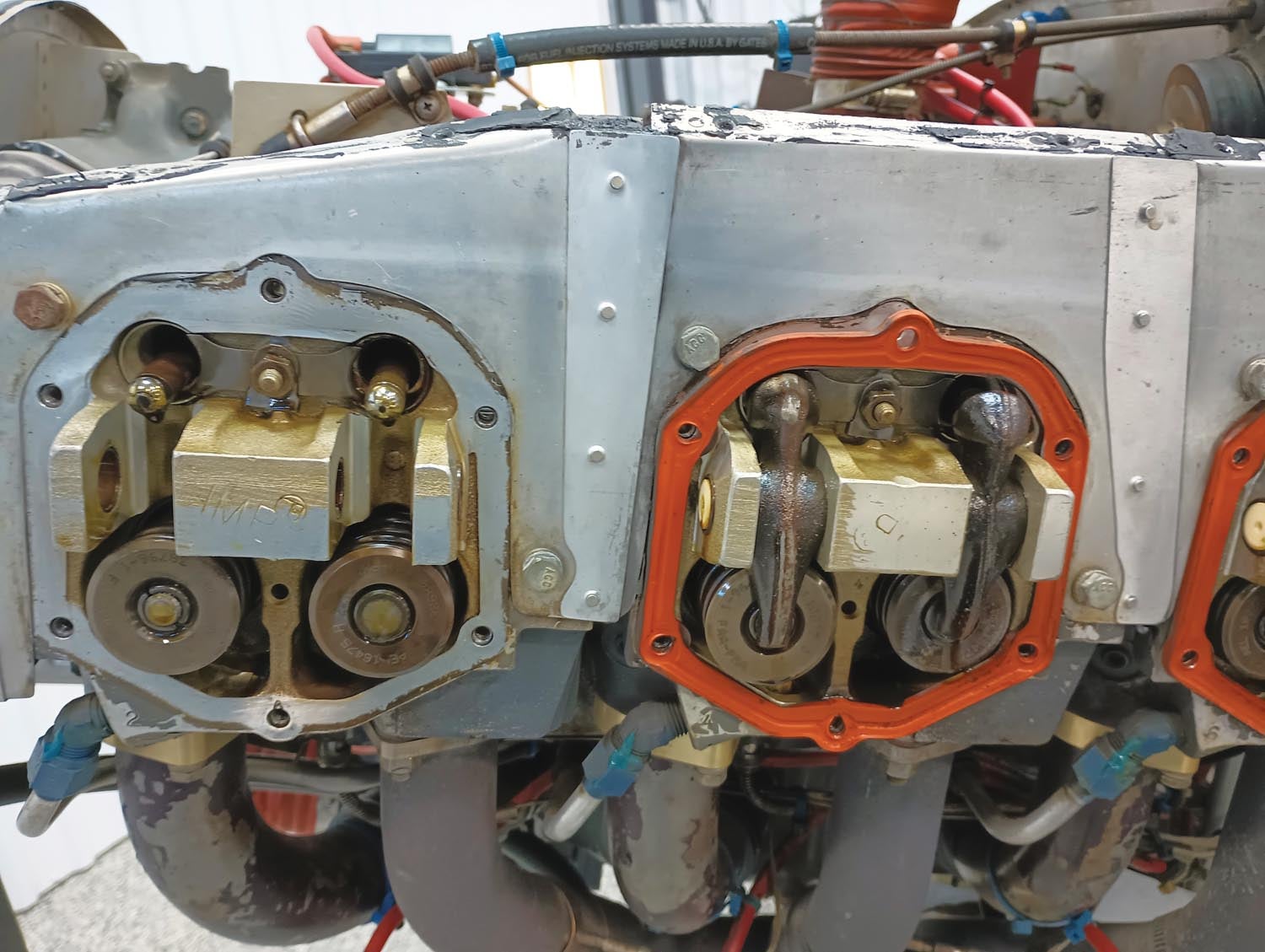
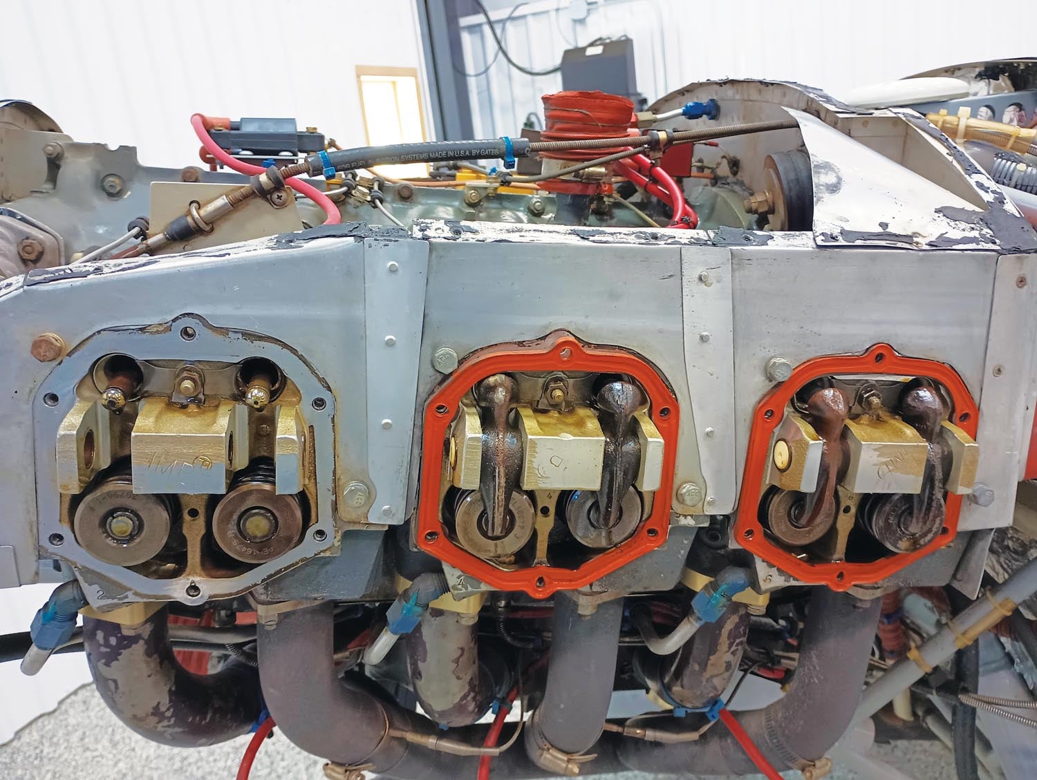
After removing the cowl, remove one spark plug from each cylinder, then remove each of the valve covers. You may want to keep an oil drip pan or some old cardboard under the engine, as oil is likely to spill out as each valve cover is removed.
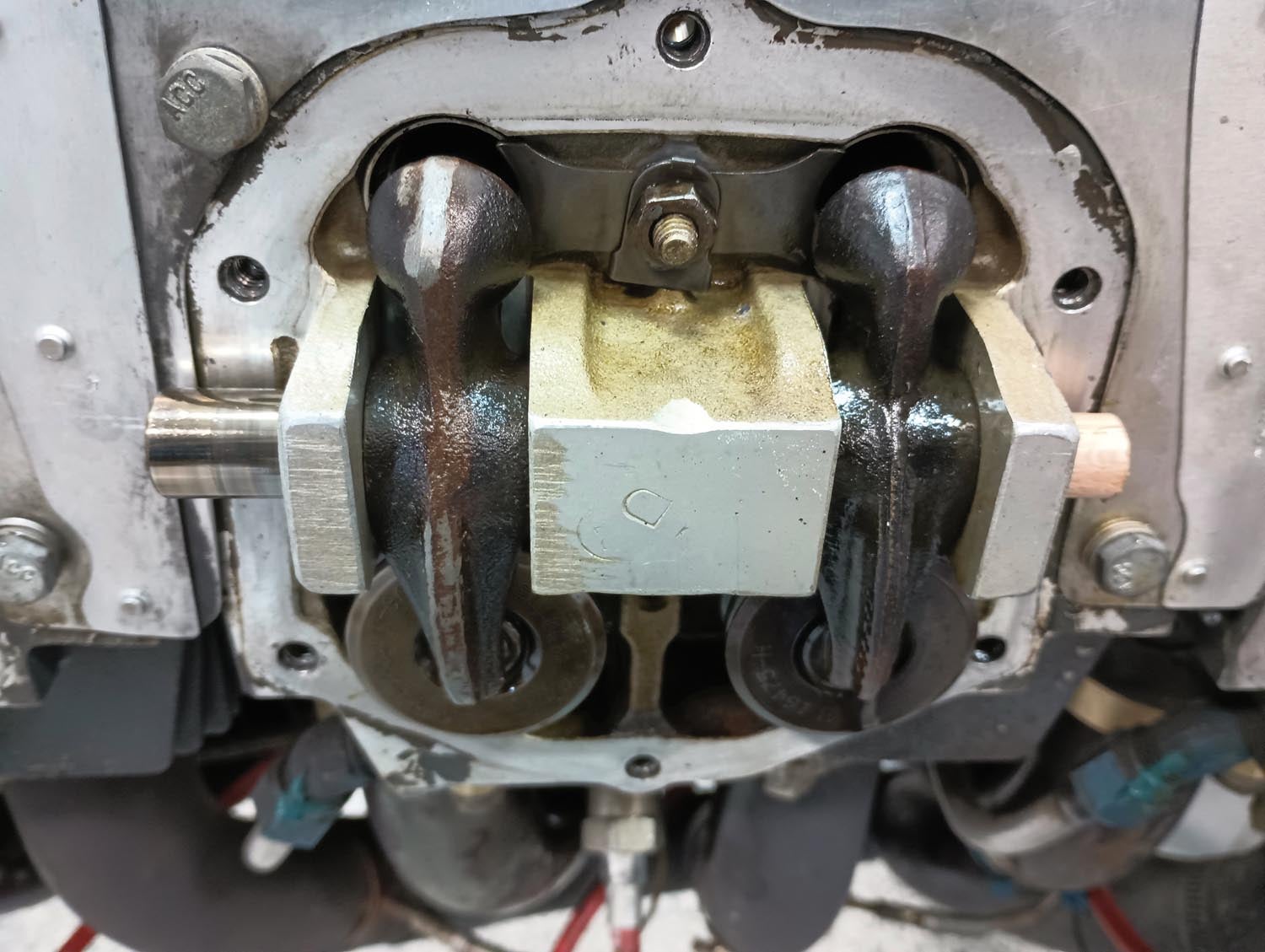
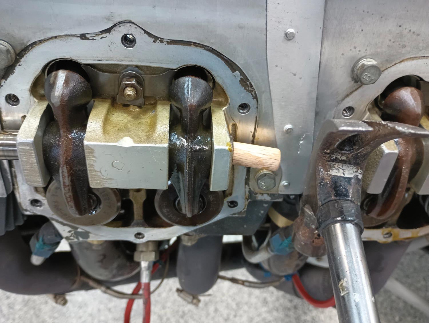
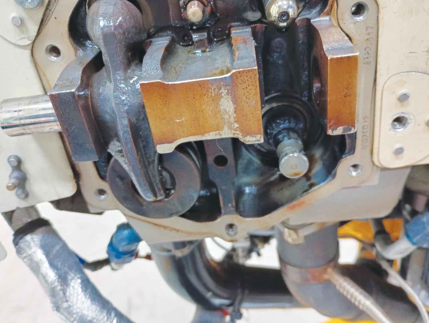
With the valve covers off, the rocker arms, rocker arm shaft and valve stems/springs are revealed. On parallel-valve engines the rocker shaft runs through both rocker arms. The rocker arms are pushed up by the pushrods, causing them to rock and press down on the ends of the valves. The first step in removing the rocker arms is to remove the rocker shaft. However, before removing anything, take careful note of which rocker arm is used for the exhaust and which is used for the intake. You will want to ensure that the correct rocker arm goes back into the correct original position. Depending on the engine model, the arms may not be the same. They should have a part number stamped on the side to aid in identification. You might want to write this number down before removing them.
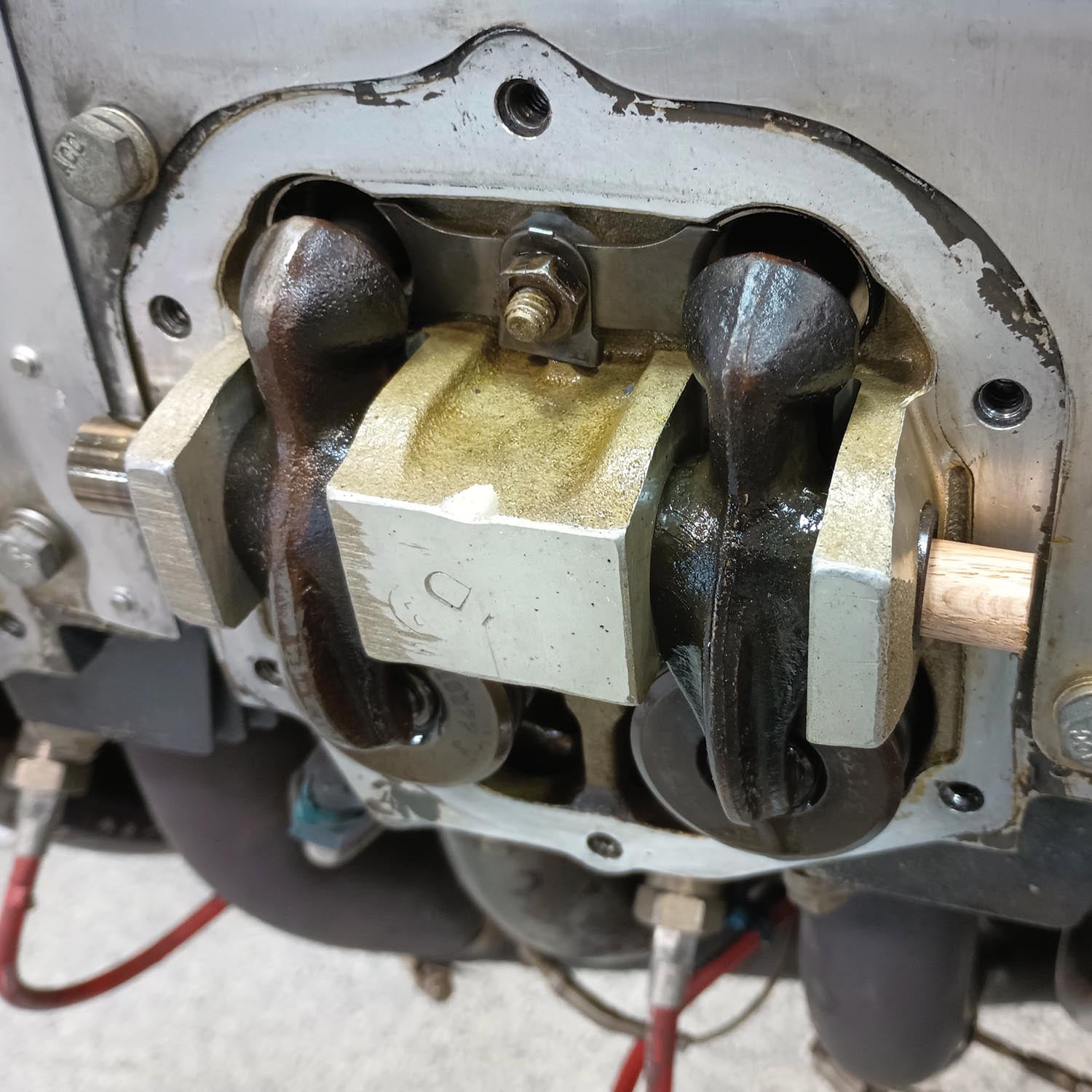
Turn the propeller by hand until the piston of the cylinder you are working on is close to top dead center on the compression stroke. Confirm this by feeling for compression at the spark plug hole or by pressing on the rocker arm above the pushrod. There should be a small amount of movement, indicating that the cam lobes are away from the lifters and the pushrods are not placing any pressure against the rocker arms. Back the propeller up about 30° and stuff a rope into the cylinder.
What kind of rope? Lycoming, in Service Instruction 1425A, says you’ll need about 8 feet of 3/8-inch nylon rope. While you’re at it, make sure it’s clean. Then, slowly move the propeller forward again until you can feel resistance as the piston is pressing on the mass of rope, pushing it against the valve face and holding it in place.

Remove the rocker shaft end caps using a dental pick. It may be possible to press the rocker shaft out by hand. If not, you can attach the Valve Wizard tool to relieve any spring pressure from the rocker arms and/or drive the shaft out, tapping gently with a hammer on a wood dowel. On my engine, 1/2-inch dowel was the right size: a little smaller than the rocker shaft outside diameter, but large enough to catch the rim of the hollow shaft. If you really want to get trick, you can 3D print a plastic cap to fit into the end of the rocker arm shaft (see “Tools and Parts” below for details).

Do not use a metal drift to drive the rocker arms out, as there is a good chance of damaging the shaft, the cylinder head or the bushings in the rockers or the rocker-shaft ears with the edge of the drift. Note that the shaft on rear cylinders can be driven to the rear of the engine and the shaft on the front cylinders can be driven to the front of the engine. However, the shaft on the middle cylinder (on six-cylinder engines) will interfere with its neighboring cylinder and cannot be fully removed. However, it can be shifted one way to remove one rocker and the other way to remove the other rocker as needed. Removing all the valve covers at once provides a little more room to work without the adjacent valve cover getting in the way.
Isn’t This Cool?
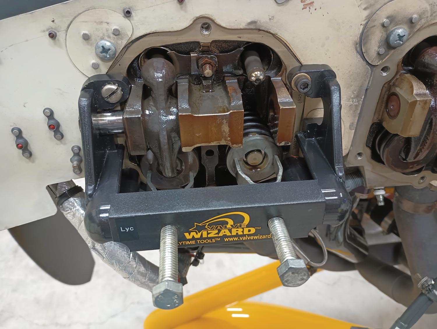
Once the rocker arm shaft has been removed, attach Cool Tool #1 (the Valve Wizard) to the open rocker cover screw holes. You can do this job without the Valve Wizard, but it or something similar makes the job a lot easier and less stressful than some of the alternative methods. The Valve Wizard will press down on the springs, allowing for the keepers to be removed and the valve stems to be released from the springs. Note that the design of the Valve Wizard is such that the rocker arm shaft can be driven out with the Valve Wizard installed, but if you can do this step before installing the Valve Wizard, it will provide a little more room to maneuver (albeit with the possibility of some spring pressure on the rocker arms and shaft).
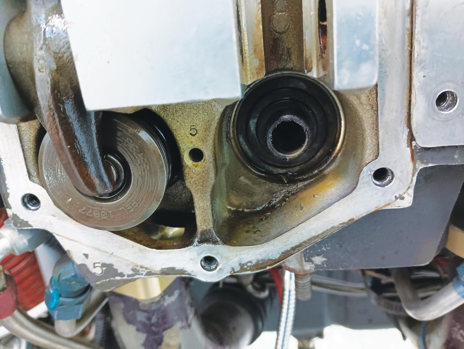
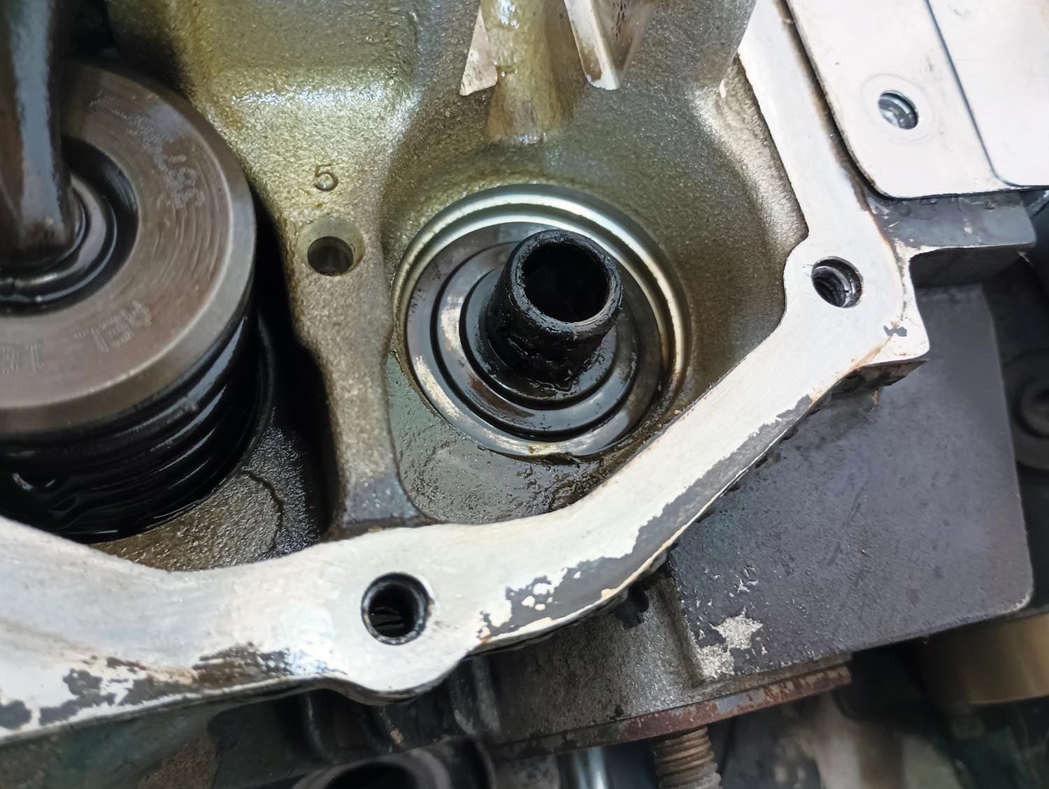
With the spring depressed, the valve stem keepers will be exposed. These are two small metal “shells” that fit down into the spring and capture a groove in the valve stem. As you remove the keepers, try to keep track of which way they were installed and on which valve, and plan to reassemble them back in the same location and orientation as they were removed. I have heard advice that this doesn’t matter but I’ve also heard advice that it does, so keeping track of what goes where seems like cheap insurance. Keep a small telescoping magnet tool nearby to help remove the keepers without dropping them into the Twilight Zone that is the hangar floor (where small parts disappear, never to be seen again).
With the keepers removed, the Valve Wizard can be removed along with the springs on the valve. A portable drill with a light torque setting makes faster work of installing and removing the tool.
Exhausted

You can check the wobble on both exhaust and intake valves, but the ones most likely to be troublesome are the exhaust.
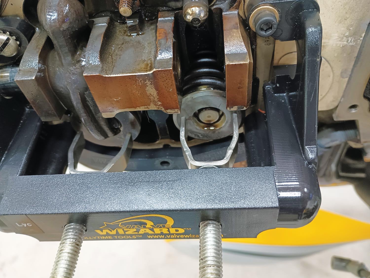
With the rocker arms, springs and keepers out of the way, Cool Tool #2 can now be used. This is the fixture tool that will hold a dial gauge to check the amount of wobble at the end of the valve. Included with the tool is a short stem that connects onto the end of the valve stem. Connect this stem, then pull the prop back far enough so that the valve can be pushed partway down into the cylinder. This moves the valve so its wiggle won’t be limited by the valve touching its seat and lines the tool stem up with the dial gauge, held in place by the fixture tool. Using finger pressure, push the stem away from the dial gauge, zero the gauge, then push the stem toward the dial gauge. The total amount of movement should be within the limit for your engine as published in Lycoming Service Bulletin 388C. On my IO-540, the limits for total movement are 0.015–0.030 inches.
If the wobble check passes, then the disassembly process can be reversed. However, if there isn’t enough wobble, the trash in the valve guide will need to be cleaned out with a reamer.
Take Out the Trash
This is where it gets a bit scary if you’ve never done it before; the valve needs to be pressed into the cylinder far enough to where it is completely out of its guide, so that the guide can be reamed. However, once you’ve done it a few times, it won’t be nearly so intimidating, so long as you follow some key steps.

To obtain good access to the valve inside the cylinder, remove the exhaust pipes—this provides a nice, open view of the valve, with sufficient room to use some mechanical fingers to grasp the valve stem as it comes out of the guide. However, before pushing the valve too far into the cylinder, I recommend obtaining a length of welding rod or coat-hanger wire. Bend a U shape in the end by wrapping it around a 1/2-inch bolt. Make sure that the top of the U is tight enough that the wire will go down into the top spark plug hole without pressing against the side of the hole. If it presses against the sides of the hole, it will catch on the spark plug hole threads when you try to remove it, which will cause it to expand and be very difficult to remove (ask me how I know this). Experiment with different bends until you can easily push the wire into the spark plug hole and capture the valve stem with the hooked end of the wire. Along with the mechanical fingers, this wire provides a second point of contact with the valve, making it much easier to line it up with the valve guide later on. It will also allow the valve to be suspended just outside of the valve guide while the guide is being reamed.
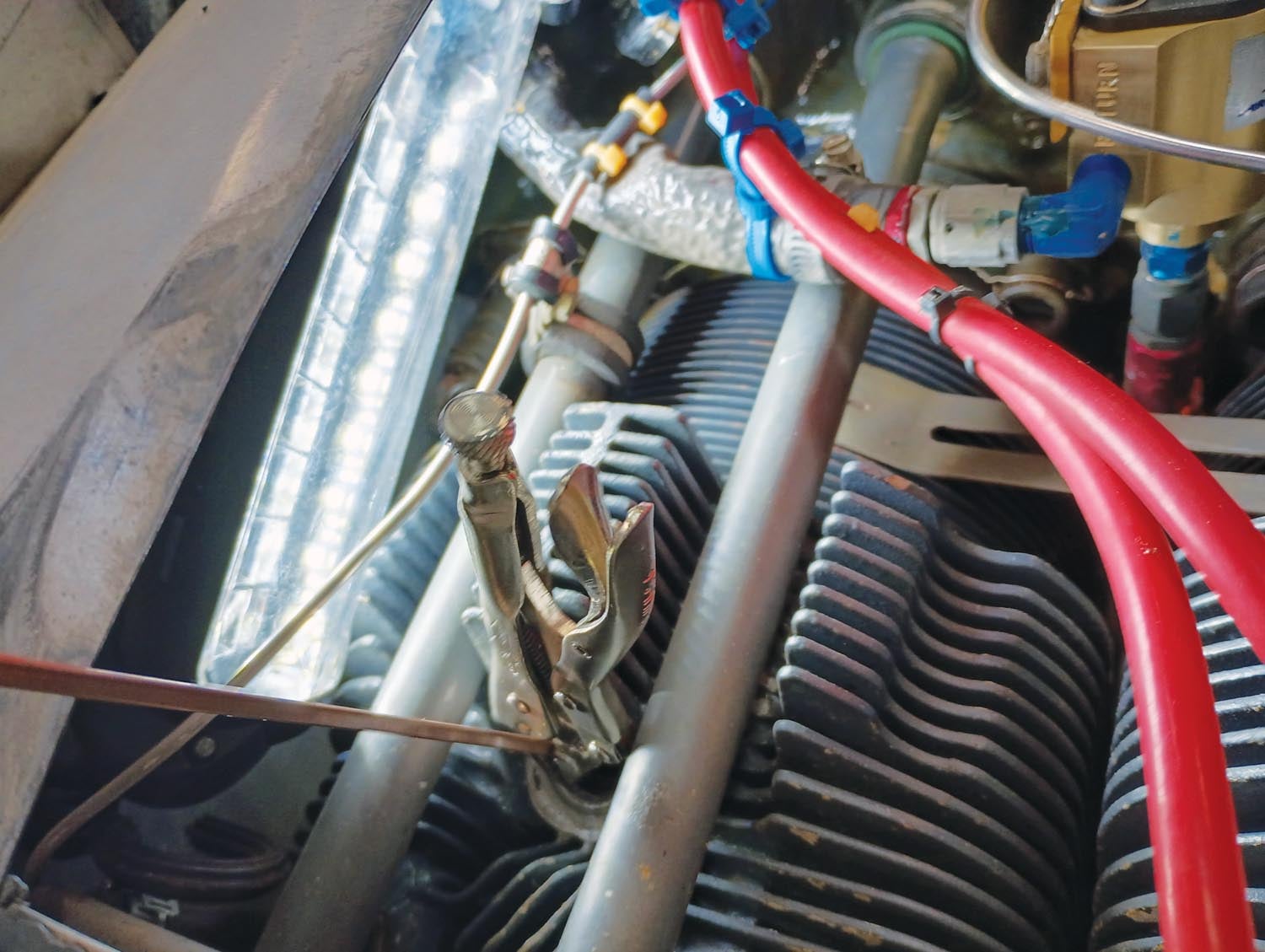
With the hooked wire in place through the top spark plug hole and around the valve stem, bring the mechanical fingers up through the exhaust port and grasp the valve stem. Now you have two tools holding the valve and can slowly and carefully work it out of the guide. Once free of the guide, use some Vise-Grips to clamp the wire and help hold the valve in place, suspended in the cylinder.

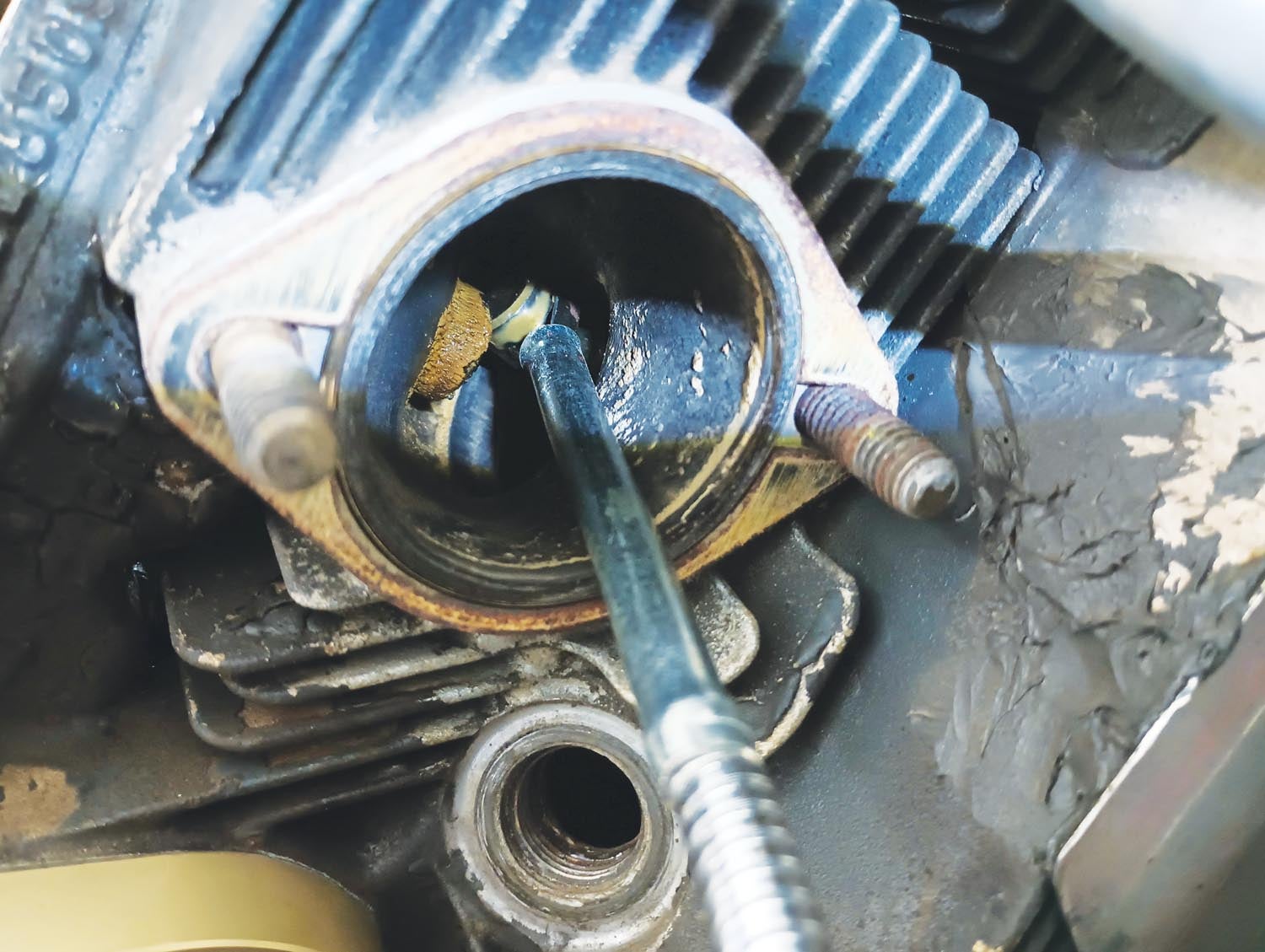
Check Lycoming Special Service Publication 1776-5 for the valve guide service limits appropriate for your engine. On mine, the exhaust limits are 0.4985–0.4995 inches. Start with a reamer equal to the smaller measurement. Coat the reamer with grease (to help capture the trash so it doesn’t fall into the cylinder) and then gently work it into the valve guide, turning by hand. I found that I could hold the end of the reamer and turn it by hand without any kind of wrench. Work the reamer a little way into the guide while turning it, then keep turning and pull it back out. Clean the trash off the end of the reamer, apply new grease and then repeat the process, going a little deeper into the guide each time until all the way through. By going slowly and regularly cleaning the reamer, it should be possible to clear the guide without dropping any trash into the cylinder. The idea here is that we are removing the caked-on carbon bits, not the metal of the guide itself.

Once the guide has been cleaned, work the valve stem back into the guide. A small telescoping magnet tool can be inserted through the valve guide to capture the end of the valve stem and help direct it back into the guide, along with the mechanical fingers and wire hook still holding the valve. The combination of the three of these tools should make the process fairly straightforward.
With the valve back in position, repeat the wobble check to confirm that the new wobble is now within limits. If it is still too tight, you may need to go to the next size reamer (e.g., 0.0005 inch larger) or inspect the valve stem itself for any deposits that will need to be removed.
If there are deposits right at the end of the valve stem, it can be polished with a Scotch-Brite pad with the valve in place in its guide (a moderate portion of the stem sticks out of the top of the guide when the valve is fully closed and some is accessible through the exhaust port with the valve fully open). However, if this is not enough, it will be necessary to drop the valve down into the cylinder and bring its stem out the exhaust port or a spark plug hole. This was not necessary in my case and hopefully you won’t need to do it, either. I imagine it requires some patience and dexterity to get everything lined up to go back into the valve guide afterward.

Once the wobble check shows that the valve is back to being within limits, that cylinder can be reassembled before moving on to the next one.
In many cases, silicone rocker cover gaskets can be reused, but if they have been squished too far out of shape, new ones will be needed. Note that the torque value for these gaskets is critical and very low. It is only 35 inch-pounds (not foot-pounds). Going tighter than this will deform the gasket and cause it to leak.
One caveat on reusing these gaskets: Mine seemed to be fine when reassembled, but several hours of operation later, new oil leaks developed, which were traced to two of the gaskets that split at the bottom screw hole. In addition, two small silicone bits made it through the oil drain tubes (the ones connected to the chamber under the rocker cover) and were captured by the cylindrical screen at the bottom of the oil pan (even on engines with an oil filter, this screen should be checked at every oil change).
I found that by the time I got to the last cylinder on my engine, I could get it done from start to finish (for the wobble check portion) in about 45 minutes. Actually cleaning out the guide took another hour or two, going slowly and carefully. Completing this task was very satisfying. In my case, the next start was easy and uneventful, with all cylinders firing smoothly as the engine came up to temperature. Hopefully good for another 500 hours before the next check!
![[Credit: Lisa Turner]](https://www.kitplanes.com/wp-content/uploads/2026/02/Fuel-Selector.jpg?w=218&h=150&crop=1 "Fuel Follies")


This procedure works well on Continental engines too.!! My GO-300 developed a non-firing cylinder on a cold start. Removing the cowl I found #3 cylinder cold, and the exhaust vale stuck wide open. !!
It took 6 passes of the reamer to get all the ‘lead-crud’ out of the exhaust guide.
This cylinder only had 350 hours on it.
I use Phillips 20w-50 with Camguard, and 40 hr oil changes and filter….fewer now with high lead in the oil analysis.
I lean aggressively on start and taxi, in cruise…the exhaust stacks are a light gray…
So, I’ll be doing the ‘wobble-stuck valve’ check in another 300 hours, just to be safe.
I’ll be using G100UL as soon as it’s available here.!!
I don’t understand. If you ream the guide out larger there will be more clearance between it and the stem which will allow more lateral movement (wobble).
The reamer is the one specified by Continental that allows 0.0015 to 0.002 inches clearance, which is the specified size for a new guide. The lead/carbon build up closed the clearance to ‘0’.
The Valve stem was so stuck that I had to use a hammer and a brass drift to get the valve out of the guide.
The reamer is only removing lead deposits and returning it to its original specification. You shouldn’t be removing metal.
If one has gone thru all the trouble to do the “rope trick” and ream the guide, wouldn’t it make sense to go the little bit extra and lap the valve prior to reassembly.
That is certainly an option and is a good idea if there is any question about the valve sealing properly against the valve seat. It’s certainly quicker to lap the valves if the rockers and springs have already been removed. However, the symptoms that would prompt each activity are different: Reaming the valve guides is a way to address a sticking valve, whereas lapping the valve is a way to address a valve which is not seating properly, which can be indicated by poor compression (leakage past the valves) and/or a hot spot on one side of the valve face, which might be seen on a borescope image. It’s also worth noting that a poorly sealing valve can also be caused by excess wear in the guide, such that the valve does not close consistently against its seat. This could show up by movement in excess of the tolerance in the wobble check. If this is the case, neither lapping nor reaming is likely to help and replacement of the valve guide might be indicated.
By using a straight reamer, it will follow the guide without cutting any offset.
The reamer is only removing the lead buildup. With each pass I could see only ‘black crap’ on the grease on the reamer…no brass.
It took 12 passes to get the reamer to go the full length of the guide.
Then I used a spare exhaust valve, inserting the stem into the guide to see how tight it was.
So, the valve should go back to it’s exact location.
I would think that the ‘rope trick’ is a holdover from WWII when clean shop air was not available in the field. A little air pressure in the cylinder through the spark plug hole is sufficient to keep the valve against the seat. Naturally, procedure updates must be cleared through the FAA and manufacturer.
As an aircraft engineer myself, I loved the detailed approach for the less experienced tinkerer.
Well written and informative.
Comments are closed.