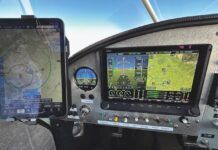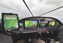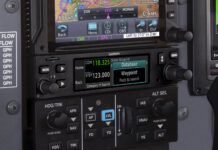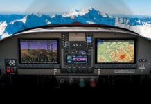
In 2010, I moved instrument components around in my GlaStar Sportsman to allow use of a two-screen G3X, which brings the primary flight display (PFD) and multifunction display (MFD) together right in front of the pilot. Why, aside from the fact that I seem to be incapable of EFIS monogamy? Because I feel this arrangement is ergonomically ideal; you get a combined looking forward and looking down set of views that offer excellent situational awareness and really simplify your instrument scan. All the flying over the six months since have proven the efficacy of that approach-the side-by-side screens are sweet.
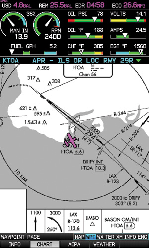
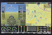
Adding the EIS strip to the MFD definitely squishes the FliteCharts display, but it all works. In a recent software update, Garmin made it possible to move the EIS strip without having to reboot the system, so you can shift the engine gauges to the PFD while flying approaches, if you like.
Only one thing was missing. As has been the case since the airplane was built in 2006, engine monitoring was handled by a Dynon EMS-D120 located in front of the copilot. Two EFIS generations ago (as this airplane ages), there was a Dynon EFIS-D100 on the left side of the panel and, for a time, an EFIS-D10A (as a backup) situated in the main instrument scan. Either of these units could display an engine page, thereby putting all the powerplant data into the pilots immediate scan. The Dynons and Garmins don’t talk, so all of the engine indications were left waaay over there on the right side of the panel.
So when Garmin finally settled on sensor kits for the G3X, I found myself signed on to test, which is not a bad thing because it would allow me to remove my old engine monitor, combine the data on one system, and once again have all the engine indications right under my nose-where they belong.
Miles of Wires
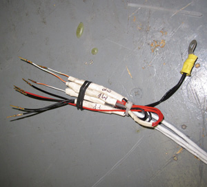
This partial harness shows just the powered pressure sender wiring.
There are two pieces of avionics in a modern airplane that cause no end of wiring and systemic challenges because of all the other systems they touch: audio panels and engine monitors. You don’t think of it until you begin to tick off all of the pieces of information the engine monitor (hereafter called EIS, for engine instrument system) needs. Of course, you have all-channel EGT (exhaust-gas temperature) and CHT (cylinder-head temperature), plus oil temp and pressure, fuel pressure and fuel flow-I wouldn’t be without a fuel computer on board. Oh, but were not done. You need to measure volts and amps. You might also want to get fuel level, though in my case, I rely on the mechanical gauges in the wingroots. Add manifold pressure and tach. Trim indication? Sure, thats handy. See what I mean? Lotsa stuff.
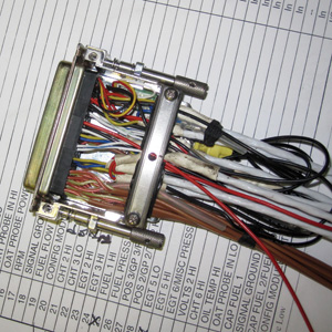
Stuffed like a Tokyo subway, the EIS connector shell demands delicate hands and a sharp eye.
At least the EIS doesn’t need to be fed outside-air temp, altitude and GPS position/speed information to calculate fuel endurance, fuel economy and engine power; it shares with the rest of the electronic flight instrument system (EFIS). Which, to be fair, so did the Dynon EFIS/EMS combo when they were installed.
Getting Started
The logical first step seemed to be to create a new harness for the G3X/EIS interface. Garmins is not a distributed system-its basically all in one. The EIS hardware lives in the aluminum-cube GSU module that also houses the main processor and AHRS (attitude heading reference system) module, along with the pitot/static sensors. In a normal G3X system (without EIS), you will have at least one display (a GDU) plus one (and only one) GSU. Add a remote magnetometer and an OAT probe, and you’re done.
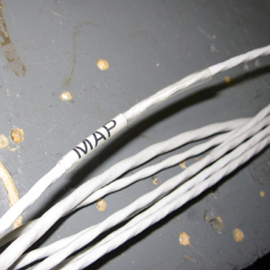
Because there are so many wires about, its critical to label each one.
Some EFIS manufacturers combine all the parts into one box; the Dynon FlightDEK-D180 is like that-all of the sensors plus the EIS are in one box. Same goes for the Advanced Flight Systems modules. Grand Rapids Technologies, MGL Avionics and Dynon, in its new SkyView system, prefer small remote modules to add new functions, which offers the opportunity to place the module where the great bulk of wires leading to it will not cause problems elsewhere behind the panel, but also requires you to find a place for the module. Its all a trade-off, one that the software and hardware designers seem happy to argue about internally.
Location, Location
I originally thought about mounting the systems GSU under the Sportsmans floorboards, because it almost fit, but actually thought far enough ahead to realize that adding the EIS would require long, heavy wire runs. (Plus, I was concerned about heat.) Currently, the GSU is on a tray less than 6 inches behind the firewall, almost directly behind the display units, with the connectors facing forward. Therefore, running the harness to the engine-where the bulk of the EIS wires need to go-would be a straight shot forward, through the firewall, and on to the sensors. This orientation was a bit of serendipity-as an early adopter of the G3X, the hardware was a bit ahead of the documentation and I was told that the GSUs orientation was fixed. In the time since, we know that the GSU can be orientated several different ways.
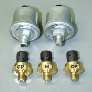
The Kavlico pressure sensors (in thelower row) compared in size to their Dynon equivalents.
Only one problem. All of the existing EIS cabling from the instrument and through the firewall was on the other side of the panel. In a retrofit, you quickly discover that you get the opportunity to both create a new installation and carefully decommission the other. I estimate that of the 50 hours required for the swap, a good 10 to 12 came from removal of old equipment-not an issue for new installations, of course, but something to keep in mind for those of you with flying ships.
Back to the harness, then. Garmins architecture uses a 78-pin, four-row, high-density connector for the EIS. On the surface, thats not a big deal, though I did wonder why the company didn’t opt for low-density D-sub connectors like everyone else uses. (Garmin engineers later explained that it would require too many individual connectors to do the job.) The existing Dynon EMS-D120 uses a 25-pin D-sub for the thermocouple (EGT/CHT) harness and a separate 37-pin D-sub for everything else, plus it sells prewired harnesses (built by SteinAir) that reduce the installation to terminating the other end of the harness. At this time, Garmin does not offer a prebuilt harness-now Im a firm believer that the company should.
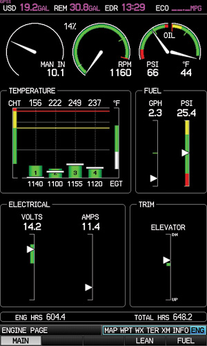
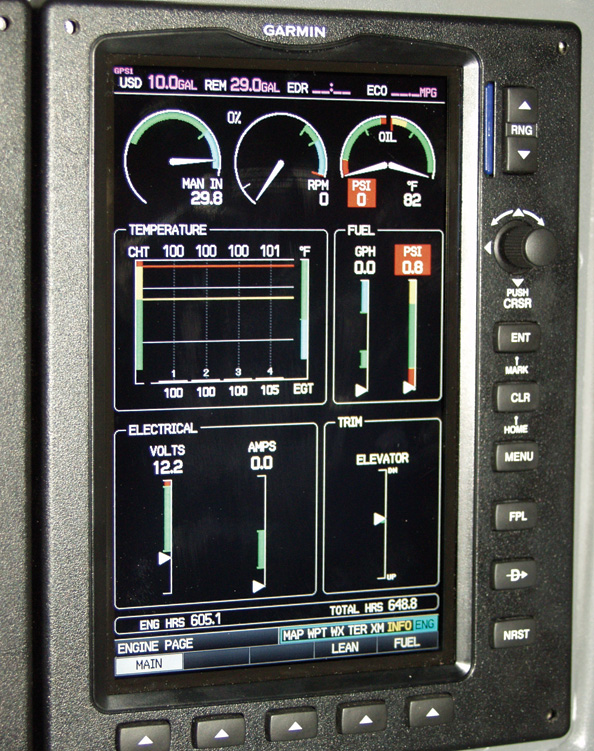
The dedicated ENG page on the multifunction display.
High-density D-subs will accept wires only as large as 22 gauge. Hmmm. Well, that meant I couldn’t use anything from the spool of 20-gauge thermocouple wire I had around. Nor could I use the 20-gauge multiconductor shielded wire left over from another project. A call to SteinAir had 25 feet of 22-gauge T-couple wire and 25 feet of multiconductor shielded wire on the way
Working with very fine wire in a tightly bundled connector forced me over to my local Harbor Freight for an inexpensive magnifying lamp. This is the first tool you really want, along with a good set of wire strippers-I prefer the Ideal Stripmaster-a four-way pin crimper and machined high-density pins, all of which I bought from B&C Specialties years ago. Don’t even think about soldering wires this small.
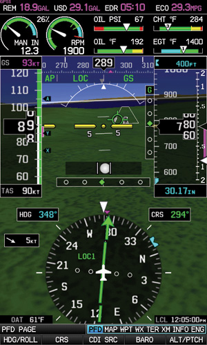
Should you elect to put the EIS on the main display (PFD), the number of data fields is automatically limited.
Reading the schematics and other related materials is essential, of course, but fully understanding the guidance is critical. I committed the first mistake during the initial part of wiring by making some assumptions about the way the sensors work in the G3X EIS. What you need to know is that most of them are so-called powered sensors. Lets look at the oil-pressure system as an example. The Kavlico (brand name) sensor has three wires, one for a DC power supply, one for ground and one for the signal sent back to the EIS. Most of the common sensors are unpowered resistance-the value of what the sensor is measuring changes the internal resistance, which the EIS then converts back to PSI or degrees or whatever. Some of these are floating ground, so that you must connect the HI and LO wires to the EIS for it to read, but many are referenced to the aircrafts common ground. Like this, you might have to run only one wire to the sensor, which uses the chassis ground for the return path.
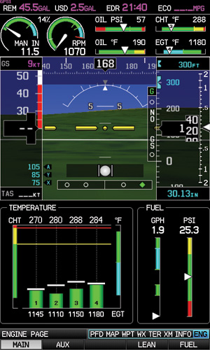
In a single-screen system, the dedicated engine (ENG) page replaces the HSI or moving map when selected.
Garmin further complicates matters by giving you only one sensor-power pin. Whats more, you’re expected to join all of the pressure LO wires together with a fourth pin enigmatically labeled XDCR PWR OUT LO (GROUND). So where some engine monitors require three wires for manifold pressure, fuel pressure and oil pressure, you have nine in the G3X EIS, plus the need to join the XDCR LO lines and distribute the power-supply line three ways.
The only logical way to do this is to bring these wires together inside the EIS connector shell and run pigtails back and forth. It doesn’t take much of this to make the already densely packed connector bulge at the seams. Why are we doing this? Garmin engineers said that the company was only following G1000 orthodoxy, which Im sure seemed logical at the time. It also seems certain that the next generation of Experimental-class EFIS/EIS will be more like our industry standards: simple.
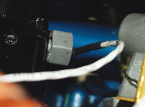
Where some engine monitors can pick up engine speed from a magneto P lead, the Garmin EIS uses a magnetic sensor threaded into a magneto vent hole. This is the Bendix 1200-series installation.
So, the Upside
Merging the engine monitoring functions into the G3X provides definite benefits. For one, the EIS now inhabits a 1-inch strip along the top of the MFD, nicely combining all of the critical readouts in one place, right in the middle of your instrument scan. Whats more, Garmin recently updated the software so you can change the EIS location on the fly, which comes in handy when you want to use the instrument approach charts on the MFD; they scale better when the EIS strip is somewhere else, like on the PFD.
A separate page on the MFD provides all the engine readouts in one place, including a full vertical-tape presentation of CHT and EGT, and includes soft keys to invoke the very good and accurate lean-find mode and manage the fuel totalizer functions. Now that it knows fuel consumption and fuel on board, the G3X can plot circles on the MFD showing your actual range to both a preset reserve amount of fuel and until the tanks are empty.
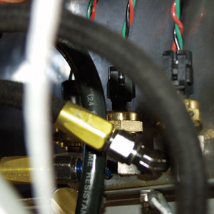
In the Sportsman installation, a three-port split manifold houses the three pressure senders-manifold, oil and fuel-for connection through the standard hoses and AN fittings.
Garmin gives you myriad ways to tailor the displays, enabling the choice of ranges (how high and low the arcs and linear scales are) and colors, as well as tick marks and other goodies to help you understand the parameters at a glance. In this respect, the EIS is extremely well done and flexible almost to a fault. I recommend plugging in the factory numbers for your engine first and experimenting later.
In the Air
In practice, the system works very well. The Kavlico pressure probes are smooth-or at least the software that interprets them is-and all indications have a solid, sophisticated presence. It was a delight to see stable oil-temperature indications after 650 hours of the Dynons wagging OT needle. After a few flights, I had the fuel-flow module (the Electronics International Red Cube) calibrated; now the actual consumed and the calculated number are always within half a gallon. After some initial software tweaks, the EIS presentation is clear, seemingly accurate and professional looking.
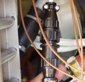
Overkill central. Mating the main harness to the individual sensors is left to the builder. These are AMP circular connectors that are probably too robust for the job, but they allow easy replacement of the sensors and are a far better alternative than soldering.
One final note on G3X/EIS benefits is that now all of the data logging is in one place. Insert an SD memory card into the PFD, and the G3X will keep track of nearly all of the parameters it measures, including location, attitude/altitude/airspeed, autopilot modes, nav sources and all of the engine details. The number of files it can store depends on the size of the card. The largest file I have on hand is 5.4 megabytes for a 4.8-hour flight, but the file size per hour will vary by the number of features you have hooked into the EIS, including things like whether you have fuel levels monitored (I dont) or how many cylinders your engine has.
The price of the Garmin sensor kit is around $1200-added to the cost of the G3X system, of course. Once through a non-trivial installation process, you get wonderful integration and an undisputed savings of panel space.
For more information on the G3X, visit www.garmin.com.

